RadiSys EPC-6320 Application guide

Artisan Technology Group is your source for quality
new and certied-used/pre-owned equipment
• FAST SHIPPING AND
DELIVERY
• TENS OF THOUSANDS OF
IN-STOCK ITEMS
• EQUIPMENT DEMOS
• HUNDREDS OF
MANUFACTURERS
SUPPORTED
• LEASING/MONTHLY
RENTALS
• ITAR CERTIFIED
SECURE ASSET SOLUTIONS
SERVICE CENTER REPAIRS
Experienced engineers and technicians on staff
at our full-service, in-house repair center
WE BUY USED EQUIPMENT
Sell your excess, underutilized, and idle used equipment
We also offer credit for buy-backs and trade-ins
www.artisantg.com/WeBuyEquipment
REMOTE INSPECTION
Remotely inspect equipment before purchasing with
our interactive website at www.instraview.com
LOOKING FOR MORE INFORMATION?
Visit us on the web at www.artisantg.com for more
information on price quotations, drivers, technical
specications, manuals, and documentation
Contact us: (888) 88-SOURCE | sales@artisantg.com | www.artisantg.com
SM
View
Instra

HARDWARE
REFERENCE
www.radisys.com
007-01490-0002
• April 2005
Introduction 1
Configuration and Installation 2
Operating System Installation 3
BIOS Configuration 4
Theory of Operation 5
Message Codes A
Interrupts B
Connectors C
Error Messages D
Flash Memory Addresses E
Re-Programming the Flash Chip F
Carrier Card Design G
EPC-6320/21 Test Board H
EPC®-6320/21
Artisan Technology Group - Quality Instrumentation ... Guaranteed | (888) 88-SOURCE | www.artisantg.com


April 2005
Copyright ©2005 by RadiSys Corporation.
All rights reserved.
EPC and RadiSys are registered trademarks of RadiSys Corporation. ASM, Brahma, DAI, DAQ, MultiPro, Promentum, SAIB, Spirit, and
ValuePro are trademarks of RadiSys Corporation.
DAVID, MAUI, OS-9, OS-9000, and SoftStax are registered trademarks of RadiSys Microware Communications Software Division,
Inc. FasTrak, Hawk, and UpLink are trademarks of RadiSys Microware Communications Software Division, Inc.
†All other trademarks, registered trademarks, service marks, and trade names are the property of their respective owners.
Artisan Technology Group - Quality Instrumentation ... Guaranteed | (888) 88-SOURCE | www.artisantg.com

iii
Contents
Preface
About this Guide..................................................................................................................................................................................................... 1
Notational Conventions ............................................................................................................................................................................... 1
Where to get More Information .......................................................................................................................................................................... 2
About the EPC-6320/21 ............................................................................................................................................................................... 2
About Related RadiSys Products................................................................................................................................................................ 2
About Related EPC-6320/21 Components .............................................................................................................................................. 3
Other................................................................................................................................................................................................................ 3
Chapter 1: Introduction
Features..................................................................................................................................................................................................................... 5
Specifications ........................................................................................................................................................................................................... 7
Environmental................................................................................................................................................................................................ 7
Additional Specifications.............................................................................................................................................................................. 8
Power............................................................................................................................................................................................................... 9
Chapter 2: Configuration and Installation
Before you Begin .................................................................................................................................................................................................... 11
Installing the EPC-6320/21 PMC on the Carrier Card..................................................................................................................................... 11
Using the 3-Pin Connector.......................................................................................................................................................................... 11
Booting the EPC-6320/21 via MBA (Managed PC Boot Agent) ................................................................................................................... 12
Maintaining and Upgrading the EPC-6320/21 ................................................................................................................................................. 12
Disconnecting the EPC-6320/21 PMC from the Carrier Card ............................................................................................................. 13
Chapter 3: Operating System Installation
Installing Red Hat Linux......................................................................................................................................................................................... 14
Installing Red Hat on a Separate Computer............................................................................................................................................ 14
Installing Red Hat 7.3 or Later over the Serial Port ................................................................................................................................ 15
Installing MontaVista Linux ................................................................................................................................................................................... 17
Configure the Host to Boot EPC-6320/21 over the Network .............................................................................................................. 17
Extract the Kernel Source and Filesystem ...................................................................................................................................... 17
Configure DHCP .................................................................................................................................................................................. 17
Configure TFTP..................................................................................................................................................................................... 19
Red Hat 7.x............................................................................................................................................................................................. 19
Configure NFS...................................................................................................................................................................................... 20
Network Boot the Kernel ................................................................................................................................................................... 20
Install MontaVista Linux to a Hard Drive.................................................................................................................................................. 21
Installing VxWorks................................................................................................................................................................................................... 23
Requirements................................................................................................................................................................................................. 23
Installation....................................................................................................................................................................................................... 23
Sample Code ........................................................................................................................................................................................................... 24
DHCP ............................................................................................................................................................................................................... 24
TFTP.................................................................................................................................................................................................................. 25
Exports............................................................................................................................................................................................................. 25
Artisan Technology Group - Quality Instrumentation ... Guaranteed | (888) 88-SOURCE | www.artisantg.com

Contents
iv
Chapter 4: BIOS Configuration
BIOS Setup Screens................................................................................................................................................................................................ 27
Menu Map ...................................................................................................................................................................................................... 27
Navigation....................................................................................................................................................................................................... 27
Main Setup Menu .................................................................................................................................................................................................. 28
Primary Master/Slave Sub-Menus ............................................................................................................................................................. 29
Advanced Menu ...................................................................................................................................................................................................... 33
PCI Configuration Sub-Menu...................................................................................................................................................................... 35
PrPMC Customizations Sub-Menu .................................................................................................................................................. 36
PCI/PNP ISA UMB Region Exclusion Sub-Menu .......................................................................................................................... 37
PCI/PNP ISA IRQ Resource Exclusion Sub-Menu......................................................................................................................... 38
Console Redirection Sub-Menu................................................................................................................................................................. 39
I/O Device Configuration Sub-Menu ........................................................................................................................................................ 41
Boot Menu................................................................................................................................................................................................................ 42
Exit Menu.................................................................................................................................................................................................................. 44
CMOS Save & Restore Sub-Menu ............................................................................................................................................................. 45
Chapter 5: Theory of Operation
External Interfaces................................................................................................................................................................................................... 46
Block Diagram ......................................................................................................................................................................................................... 47
Description ............................................................................................................................................................................................................... 47
CPU................................................................................................................................................................................................................... 47
Tualatin 512K LP processor Speed and Voltages .......................................................................................................................... 48
Clocking........................................................................................................................................................................................................... 48
The RadiSys 82600 ....................................................................................................................................................................................... 49
PCI Interrupts........................................................................................................................................................................................ 51
Dual PCI bus architecture .................................................................................................................................................................. 51
Local PCI Bus (Bus 0)......................................................................................................................................................................... 52
PCI Ethernet controller ....................................................................................................................................................................... 53
Backplane PCI bus (Bus 1)................................................................................................................................................................ 53
IDE Controller....................................................................................................................................................................................... 53
RTC.......................................................................................................................................................................................................... 53
Serial Port .............................................................................................................................................................................................. 53
Keyboard Controller............................................................................................................................................................................ 54
Miscellaneous I/O Interrupts............................................................................................................................................................. 54
GPIO pins .............................................................................................................................................................................................. 54
Power and Reset............................................................................................................................................................................................ 54
Appendix A: Message Codes............................................................................................................................................................................ 56
Appendix B: Interrupts......................................................................................................................................................................................... 57
Appendix C: Connectors
Connector Locations .............................................................................................................................................................................................. 58
PMC Connectors ..................................................................................................................................................................................................... 59
Jn1 connector .............................................................................................................................................................................................. 59
Jn2 Connector .............................................................................................................................................................................................. 60
Jn4 Connector .............................................................................................................................................................................................. 61
Ethernet Ports................................................................................................................................................................................................. 63
3-Pin COM Connector.................................................................................................................................................................................. 63
Null-Modem Serial Cable................................................................................................................................................................... 63
LEDs ................................................................................................................................................................................................................. 64
Artisan Technology Group - Quality Instrumentation ... Guaranteed | (888) 88-SOURCE | www.artisantg.com

Contents
v
Appendix D: Error Messages............................................................................................................................................................................ 65
Appendix E: Flash Memory Addresses...................................................................................................................................................... 66
Appendix F: Re-Programming the Flash Chip
About the Flash Chip.............................................................................................................................................................................................. 67
About Re-Programming the Flash Chip............................................................................................................................................................. 68
Before you Begin .................................................................................................................................................................................................... 68
Creating a Flash Boot Image ................................................................................................................................................................................ 69
Using phlash.exe to Re-Program the Flash Chip ............................................................................................................................................. 70
Appendix G: Carrier Card Design
PrPMC Connectors (Jn1 and Jn2)....................................................................................................................................................................... 71
General ............................................................................................................................................................................................................ 71
Power ..................................................................................................................................................................................................... 71
PCI........................................................................................................................................................................................................... 72
Jn1 .................................................................................................................................................................................................................... 72
Clocking ................................................................................................................................................................................................. 72
Arbitration.............................................................................................................................................................................................. 72
Jn2 .................................................................................................................................................................................................................... 72
Processor PMC ..................................................................................................................................................................................... 72
RadiSys-Defined PrPMC Connector (Jn4)......................................................................................................................................................... 72
IDE.................................................................................................................................................................................................................... 72
Keyboard and Mouse................................................................................................................................................................................... 73
Serial Port........................................................................................................................................................................................................ 73
Clocking........................................................................................................................................................................................................... 73
Arbitration ....................................................................................................................................................................................................... 73
RTC Battery ..................................................................................................................................................................................................... 73
Mechanical and Thermal Design......................................................................................................................................................................... 73
Power consumption...................................................................................................................................................................................... 73
Airflow.............................................................................................................................................................................................................. 74
Maximum Ambient Temperature .............................................................................................................................................................. 74
Carrier Card Schematic Samples......................................................................................................................................................................... 74
Appendix H: EPC-6320/21 Test Board
Features..................................................................................................................................................................................................................... 83
External Interfaces......................................................................................................................................................................................... 84
Specifications ........................................................................................................................................................................................................... 84
Block diagram.......................................................................................................................................................................................................... 85
Physical Interfaces................................................................................................................................................................................................... 85
Connectors and Jumpers............................................................................................................................................................................. 85
Reset Switch.......................................................................................................................................................................................... 86
Interrrupts ....................................................................................................................................................................................................... 86
Glossary.......................................................................................................................................................................................................................... 87
Index................................................................................................................................................................................................................................. 95
Artisan Technology Group - Quality Instrumentation ... Guaranteed | (888) 88-SOURCE | www.artisantg.com
Contents
vi
Figures
Figure 1-1. The EPC-6320............................................................................................................................................................................................... 4
Figure 1-2. EPC-6320/21 Ordering Configurations................................................................................................................................................... 5
Figure 2-1. Installing a PMC Module............................................................................................................................................................................ 11
Figure 2-2. Separating a PMC Module from the Carrier Card................................................................................................................................ 13
Figure 4-1. BIOS Main Setup Menu ............................................................................................................................................................................. 28
Figure 4-1. Primary Master/Slave Sub-Menus............................................................................................................................................................ 29
Figure 4-2. Advanced Menu........................................................................................................................................................................................... 33
Figure 4-3. PCI Configuration Sub-Menu.................................................................................................................................................................... 35
Figure 4-4. PrPMC Customizations Sub-Menu........................................................................................................................................................... 36
Figure 4-5. PCI/PNP ISA UMB Region Exclusion Sub-Menu ................................................................................................................................... 37
Figure 4-6. PCI/PNP ISA IRQ Resource Exclusion Sub-Menu ................................................................................................................................. 38
Figure 4-7. Console Redirection Sub-Menu ............................................................................................................................................................... 39
Figure 4-8. I/O Device Configuration Sub-Menu ...................................................................................................................................................... 41
Figure 4-9. Boot Menu .................................................................................................................................................................................................... 42
Figure 4-10. Exit Menu .................................................................................................................................................................................................... 44
Figure 4-11. CMOS Save & Restore Sub-Menu.......................................................................................................................................................... 45
Figure 5-1. Block Diagram .............................................................................................................................................................................................. 47
Figure C-1. EPC-6320: Connectors ............................................................................................................................................................................... 58
Figure E-1. Flash chip memory addresses .................................................................................................................................................................. 66
Figure F-1. Flash Chip Configuration............................................................................................................................................................................ 67
Figure F-2. Flash Chip Re-Programming Process Flow ............................................................................................................................................ 68
Figure H-1. Block Diagram: Test Board ....................................................................................................................................................................... 85
Tables
Table 1-1. Environmental Specifications ..................................................................................................................................................................... 7
Table 1-2. Additional EPC-6320/21 Specifications .................................................................................................................................................... 8
Table 1-3. Power Estimates ............................................................................................................................................................................................ 9
Table 3-1. VxWorks Command and File Descriptions.............................................................................................................................................. 24
Table 5-1. PCI Device Configuration ............................................................................................................................................................................ 52
Table 5-2. Power Estimates ............................................................................................................................................................................................ 54
Table B-1. Interrupts ........................................................................................................................................................................................................ 57
Table C-1. Jn1 Connector Pin Definitions ................................................................................................................................................................... 59
Table C-2. Jn2 Connector Pin Definitions ................................................................................................................................................................... 60
Table C-3. EPC-6320 Optional JN4 Connector Pin Definitions .............................................................................................................................. 61
Table C-4. EPC-6321 Optional JN4 Connector Pin Definitions .............................................................................................................................. 62
Table C-5. Ethernet Pin Definitions............................................................................................................................................................................... 63
Table C-6. 3-Pin Connector Pin Definitions................................................................................................................................................................ 63
Table C-7. Front Panel LED Descriptions .................................................................................................................................................................... 64
Table H-1. Environmental Specifications..................................................................................................................................................................... 84
Table H-2. Connector and Jumper Descriptions ....................................................................................................................................................... 85
Table H-3. PCI Device Configuration............................................................................................................................................................................ 86
Artisan Technology Group - Quality Instrumentation ... Guaranteed | (888) 88-SOURCE | www.artisantg.com
1
Preface
This guide describes EPC-6320 and EPC-6321 (hereinafter referred to as the
EPC-6320/21),
PrPMCs (Processor PCI Mezzanine Cards) that use the RadiSys 82600
integrated chipset to bring Intel
†
Architecture processors into ultra-dense form factors.
This
guide is for hardware and software designers, engineers, and those with a electronics
and/or programming knowledge who need to understand EPC-6320/21 operation.
About this Guide
Notational Conventions
This guide uses the following conventions:
BoldText A command or keyword.
MonoText Screen text and syntax strings.
ItalicText
Variable parameters.
All numbers are decimal unless otherwise stated.
Bit 0 is the low-order bit. If a bit is set to 1, the associated description is true unless
otherwise stated.
Notes Indicates important information about the product.
Tips Indicates alternate techniques or procedures that you can use to save time or
better understand the product.
URL Indicates a World Wide Web address.
Book/File Indicates a book or file.
ESD CAUTION
Indicates situations that may cause damage to hardware via ESD (ElectroStatic
Discharge).
CAUTION
Indicates potentially hazardous situations which, if not avoided, may result in
minor or moderate injury, or damage to data or hardware. It may also alert you
about unsafe practices.
WARNING Indicates potentially hazardous situations which, if not avoided, can result in
death or serious injury.
DANGER Indicates imminently hazardous situations which, if not avoided, will result in
death or serious injury.
Artisan Technology Group - Quality Instrumentation ... Guaranteed | (888) 88-SOURCE | www.artisantg.com

2
EPC®-6320/21 Preface
HARDWARE REFERENCE
Where to get More Information
About the EPC-6320/21
You can find out more about EPC-6320/21 from these sources:
• Readme file: Lists features and issues that arose too late to include in other
documentation.
•World Wide Web: RadiSys maintains an active site on the World Wide Web. The
site contains current information about the company and locations of sales offices,
new and existing products, contacts for sales, service, and technical support
information. You can also send e-mail to RadiSys using the web site.
Requests for sales, service, and technical support information receive
prompt response.
• Other: If you purchased your RadiSys product from a third-party vendor, you can
contact that vendor for service and support.
About Related RadiSys Products
82600 High Integration Dual PCI System Controller Data Book: This book details the RadiSys
82600 High Performance System Controller, a member of the RadiSys family of long-
life embedded PC compatible core logic. The 82600 is a highly integrated single chip
implementation of all requirements of a high performance Compact PCI Central
Resource and Peripheral Bridge including the North Bridge, South Bridge, PCI to PCI
Bridge, and a selected set of Super I/O functions targeted at embedded, PC-compatible
systems. It supports Intel Celeron†, Pentium II, and Pentium III processors with 66MHz,
100MHz and 133MHz system bus frequencies.
Note
When sending e-mail for technical support, please include information about both the hardware
and software, plus a detailed description of the problem, including how to reproduce it.
URL
To access the RadiSys web site, enter this URL in your web browser:
http://www.radisys.com
Artisan Technology Group - Quality Instrumentation ... Guaranteed | (888) 88-SOURCE | www.artisantg.com

3
EPC®-6320/21 Preface
HARDWARE REFERENCE
About Related EPC-6320/21 Components
Processor PMC standard, VITA 32-2002, Draft 0.9.
ANSI/VITA 32-2003 American National Standard for Processor PMC
, Revision 1.0
: .
PCI Specification, Revision 2.2.
PTMC PICMIG 2.15 Standard: .
IEEE Standard for a Common Mezzanine Card Family: CMC and IEEE Standard
Physical and Environmental Layers for PCI Mezzanine Cards: PMC, IEEE, Standard No.:
1386-2001 and 1386.1-2001PICMG 2.15 R1.0:ECN 2.15-1.0-001PCI Telecom
Mezzanine/Carrier Card Specification, PICMG.
PICMG 3.0 D1.0 Advanced Telecommunications Computing Architecture (ATCA),
PICMG.
Other
• For MV Linux†LSPs, contact MontaVista at this URL:
http://www.mvista.com
• For VxWorks†BSPs, contact RadiSys or WindRiver
http://www.windriver.com
http://www.radisys.com
Artisan Technology Group - Quality Instrumentation ... Guaranteed | (888) 88-SOURCE | www.artisantg.com

4
EPC-6320/21 PrPMCs (Processor PCI Mezzanine Cards) use the RadiSys 82600
integrated chipset to bring Intel Architecture processors into ultra-dense form factors.
The EPC-6320/21 includes an 933MHz Pentium†III processor with up to 1GB of
on-board SDRAM. The EPC-6320/21 also features ECC protection of memory with
single error correction and double error detection capability. Performance is maximized
with the standard 133MHz PSB and 133MHz memory bus. For maximum flexibility, the
EPC-6320/21 leverages the dual mode PCI-to-PCI bridge capability of the
RadiSys 82600 to automatically configure the bridge, based on the strapping of the slot
on the baseboard. This capability allows the EPC-6320/21 to become a Monarch
PrPMC, and provide PCI bus enumeration and service interrupts on the PCI bus or a
non-Monarch PrPMC and function as a PCI-based auxiliary processor.
The Jn1 and Jn2 connectors provide a 32-bit 33/66MHz interface to the PCI bus on
the baseboard plus power and ground. The optional Jn4 connector provides a full set
of I/O, which includes EIDE, COM, and keyboard interfaces.
•EPC-6320 provides two standard IEEE 802.3 Ethernet interfaces to the front panel
via RJ-45 connectors for 10/100/1000Base-T applications. The EPC-6320
complies with the Processor PMC standard, VITA 32-2002, Draft 0.9.
•EPC-6321 provides two standard IEEE 802.3 Ethernet interfaces to Jn4 PMC
connector and complies with the Processor PMC standard, VITA 32-2002, Draft
0.9. and PTMC PICMIG 2.15 Standard.
1
Introduction
Features...................................................................................................................................................... 5
Specifications ........................................................................................................................................... 7
Environmental..................................................................................................................................... 7
Additional Specifications.................................................................................................................. 8
Power ..................................................................................................................................................... 9
Figure 1-1. The EPC-6320
Artisan Technology Group - Quality Instrumentation ... Guaranteed | (888) 88-SOURCE | www.artisantg.com

EPC®-6320/21 Introduction
HARDWARE REFERENCE
5
1
The EPC-6320/21 can be ordered in these configurations:
Features
The EPC-6320/21 includes:
Compatibility
• Processor PMC standard, VITA 32-2002, Draft 0.9.
• PTMC PICMIG 2.15 Standard.
• ANSI/VITA 32-2003 American National Standard for Processor PMC, Revision 1.0.
Intel Tualatin LP processors in micro-FCBGA package
• 933 MHz core frequency.
• 133 MHz PSB (Processor Side Bus) frequency.
• 512 KB integrated cache on die.
• Thermal design power of 12W for 933 MHz processor.
• Switching power supply for CPU core voltage; linear supplies for interface voltages.
CPU subsystem
• RadiSys 82600 high integration dual PCI system controller:
• Dual independent PCI bus architecture.
• Monarch and non-Monarch capability on BPCI bus.
• Memory controller.
• Two 82C59 interrupt controllers.
• 82C54 timer/counter.
• 74LS612 address mapper.
• PS/2 compatible keyboard.
• SMBus host interface.
Figure 1-2. EPC-6320/21 Ordering Configurations
Configuration Description Ethernet
EPC-6320 EPC6320-933-512 512 MB SDRAM Dual Ethernet ports on the front panel.
EPC6320-933-1G 1 GB SDRAM Dual Ethernet ports on the front panel.
EPC-6321 EPC6321-933-512 512 MB SDRAM Dual Ethernet ports
out to Jn4 PICMIG
2.15 compatible pinout.
EPC6321-933-1G 1
GB SDRAM
Dual Ethernet ports
out to Jn4 PICMIG
2.15 compatible pinout.
For detailed information about the 82600 chip, see the
82600 High Integration Dual PCI
System Controller Data Book
.
Artisan Technology Group - Quality Instrumentation ... Guaranteed | (888) 88-SOURCE | www.artisantg.com

EPC®-6320/21 Introduction
HARDWARE REFERENCE
6
1
• Two 82C37 DMA controllers.
•Real-TimeClock(RTC).
• COM port support with 16550 compatible UART.
• Integrated watchdog timer.
• Clock generator that supports 133 MHz host and SDRAM clocks, and 66 MHz
PCI clocks.
• On-board memory capacity up to 512 MB or 1 GB of PC-133 compliant SDRAM
using Unigen memory module.
• 32 Mb (4 MB) +3V Intel StrataFlash memory.
• IDE support via Jn4 connector.
I/O
• Intel PCI Ethernet controller independently supporting 10/100/1000BASE-T.
Connectors
• Carrier card
• Jn1 and Jn2 connectors
Provides a 32-bit 33/66 MHz interface to the PCI bus on the baseboard, plus
provides power and ground state compatible with the ANSI/VITA 32-2003
American National Standard for Processor PMC, Revision 1.0.
• Jn4 connector (optional)
Provides a full set of I/O including EIDE, COM, and port signals.
• Front panel
• 10/100/1000BASE-T Ethernet connector
Simplifies network connections. This connector is available on the front panel.
Artisan Technology Group - Quality Instrumentation ... Guaranteed | (888) 88-SOURCE | www.artisantg.com

EPC®-6320/21 Introduction
HARDWARE REFERENCE
7
1
Specifications
Environmental
The EPC-6320/21 meets the following environmental specifications.
CAUTION
• Use the EPC-6320/21 only with compatible UL Listed computers that have installation instructions
that details user installation of card cage accessories.
• Ensure that the operating environment provides sufficient airflow (200 LFM) across the CPU board
to keep it within its temperature specification. Failure to provide sufficient airflow may result in
CPU failure.
Note
The maximum temperature decreases when the relative humidity exceeds 30%.
Table 1-1. Environmental Specifications
Parameter Conditions Detailed specification
Temperature
(ambient)
Operating +0ºC to 50ºC derated 2ºC per 1000 ft (300 m) over 6600ft
(2000m).
Storage –20ºC to +60ºC.
Relative humidity Operating 20% to 90% non-condensing 20% per hour maximum
excursion gradient.
NEBS2requires 85% operating, 90% short-term (<96 hrs) and
transitions at least 15% to 20%/hour.
Storage 5% to 95% non-condensing 20% per hour maximum
excursion gradient.
NEBS2requires 95% and transitions at least 15% to
20%/hour.
EMC1
radiated emission
Operating EN 55022:1998, Class B.
Vibration Operating 0.04g2/Hz from 5 to1000 Hz random, 10 min per sweep cycle.
Storage 0.06g2/Hz from 5 to1000 Hz random, 10 min per sweep cycle.
Shock, (un-packaged) Operating 5g, 11ms, half-sine.
Storage 15g, 11ms, half-sine.
MTBF 373,858 hours at 50ºC using Bellcor Issue 6.
Immunity
ESD1Operating (All performance criteria from IEC 1000-4-2/EN61000-4-
2:1995):
8KV direct contact, performance criteria B.
15 KV air discharge, performance criteria B.
NEBS2requires 8kV contact / 2kV+15kV air at performance
criteria B.
Artisan Technology Group - Quality Instrumentation ... Guaranteed | (888) 88-SOURCE | www.artisantg.com

EPC®-6320/21 Introduction
HARDWARE REFERENCE
8
1
1These are system level tests. Conformance of the product to these specifications may be affected by
the complete system’s ability to conform.
2The EPC-6320/21 is screened for NEBS compliance. NEBS certification, if required, is performed at the
system level.
Additional Specifications
1The PrPMC module‘s mechanical outline conforms to the dimensions defined by a single-wide,
standard-length PMC module. EPC-6320/21 complies with these size standards:
•Tall PrPMC standards: EPC-6320/21 height falls between the limits of Standard (3.5 mm) and Tall
(23.5 mm for side 2 components), as defined by Processor PMC standard, VITA 32-2002, Draft 0.9.
•ATCA standards: EPC-6320/21 mechanical height complies with carrier cards that can accomodate
a PMC Side 2 height of 8MM, but does not comply with carrier cards of single front panel width
(4HP), as defined by PICMG 3.0 D1.0 Advanced Telecommunications Computing Architecture
(ATCA), PICMG.
Radiated1Operating (Performance criteria A from IEC 1000-4-3/EN61000-4-3:1995).
Test Level 3V/m and 10V/m.
Surge Operating (Performance criteria B from IEC 1000-4-4/EN61000-4-4:1995).
Test Level 0.5kV.
Voltage dips and
interruptions
Operating (From IEC 1000-4-11/EN61000-4-11:1995):
>95% dip, 10ms—Performance criteria B.
30% dip, 500ms—Performance criteria C.
>95% dip, 5000ms—Performance criteria C.
Conducted Operating (Performance criteria A from IEC 1000-4-6/EN61000-4-6:1995).
Fast transient/burst Operating (Performance criteria B from IEC 1000-4-4/EN61000-4-
4:1995):
Test Level 0.5kV.
Table 1-1. Environmental Specifications
Parameter Conditions Detailed specification
Table 1-2. Additional EPC-6320/21 Specifications
Characteristic Value
Mechanical Dimensions174.0 mm x 149.00 mm
Thickness 1.6 mm
Connector height 10 mm
Artisan Technology Group - Quality Instrumentation ... Guaranteed | (888) 88-SOURCE | www.artisantg.com

EPC®-6320/21 Introduction
HARDWARE REFERENCE
9
1
Power
This table includes the power requirements for the 1GB memory SDRAM module.
Table 1-3. Power Estimates
Supply Max. power, Watts Typical power, Watts
+5V 13 10
+3.3V 13 11
Total power: 26 21
Note
The PMC specification limits power to 0.5 A per connector pin:
• J1–6 pins +5V: 3A maximum
• J2–9 pins +3.3V: 4.5A maximum
Artisan Technology Group - Quality Instrumentation ... Guaranteed | (888) 88-SOURCE | www.artisantg.com

10
2
Configuration and Installation
Before you Begin
..............................................................................................................................................................11
Installing the EPC-6320/21 PMC on the Carrier Card
............................................................................................11
Maintaining and Upgrading the EPC-6320/21
........................................................................................................ 12
Disconnecting the EPC-6320/21 PMC from the Carrier Card
........................................................................ 13
ESD CAUTION
Avoid causing ESD (electrostatic discharge) damage by following these conventions:
• Keep the blade in its anti-static bag until you are ready to install it.
• Install the blade (as described later in this chapter) only in a static-free environment:
• Before touching the blade, attach an ESD wrist strap to your wrist and connect its other end to the
ESD friction-lock connector at the shelf’s lower left.
• Remove the
blade
from its antistatic bag only in a static-free environment.
• Avoid touching printed circuits, connector pins, and components. Where possible, hold the blade
only by its edges or mounting hardware.
• Make the least possible movement with your body to minimize electrostatic charges created by
contact with clothing fibers, carpet, and furniture.
• Keep one hand on the shelf, if possible, as you insert or remove a blade.
• Avoid placing the blade on the shelf cover or on a metal table. The cover and metal table increase
the risk of damage because they provide an electrical path from your body through the blade.
The EPC-6320/21, like most other electronic devices, is susceptible to ESD damage. ESD damage is not
always immediately obvious. It can cause a partial breakdown in semiconductor devices that might not
result in immediate failure.
Artisan Technology Group - Quality Instrumentation ... Guaranteed | (888) 88-SOURCE | www.artisantg.com
EPC®-6320/21 Configuration and Installation
HARDWARE REFERENCE
11
2
Before you Begin
The EPC-6320/21 requires a PMC carrier.
Installing the EPC-6320/21 PMC on the Carrier Card
You install the EPC-6320/21 PMC on the carrier card as shown in the next figure.
To install a PMC module:
1. Remove and save any blank faceplate from the PMC slot in the carrier card
faceplate.
2. Position the PMC bezel through the PMC slot on the front panel.
3. Push the rear connectors into the carrier card.
4. Insert and tighten the screws on the back of the carrier card.
Using the 3-Pin Connector
The EPC-6320/21 includes a 3-pin connector that you can use to access some
COM1 signals.
Before you begin, ensure that you have a null-modem cable that connects the 3-pin
connector to your terminal.
Figure 2-1. Installing a PMC Module
3
2
41
Note
You must construct this cable; RadiSys does not supply a cable for the 3-pin connector. For pinout
information, see 3-Pin COM Connector on page 63.
Artisan Technology Group - Quality Instrumentation ... Guaranteed | (888) 88-SOURCE | www.artisantg.com

EPC®-6320/21 Configuration and Installation
HARDWARE REFERENCE
12
2
To use the 3-pin connector:
1. Attach the cable to the 3-pin connector and your terminal.
2. Start a terminal emulation program, such as Hyperterm or Telix, using
these settings:
Baud rate: 115200
Parity: None
Data bits: 8
Stop bits: 1
Flow control: None
You can now access the BIOS setup program using the methods described in Chapter
4, BIOS Configuration.
Booting the EPC-6320/21 via MBA (Managed PC Boot Agent)
1. Set the BIOS to use MBA as the first boot device:
A. Boot the board.
B. Press F2 to enter the BIOS Setup program (see page 27).
C. Go to the boot options and select MBA as your first boot choice.
D. Save your changes
E. Reboot the system.
2. Set network parameters:
A. Press F1 to enter the MBA configuration when prompted to do so. The
configuration menu displays.
B. Select TCP/IP as the boot method.
C. Select DHCP as the protocol.
D. Press 9 to save and reboot.
The board then obtains an IP address via DHCP and boots your image via TFTP with a
root filesystem via your NFS server.
Maintaining and Upgrading the EPC-6320/21
Occasionally you will want to perform maintenance or upgrades on the EPC-6320/21.
When this occurs, you must remove the board from the carrier card, repair or install the
Artisan Technology Group - Quality Instrumentation ... Guaranteed | (888) 88-SOURCE | www.artisantg.com

EPC®-6320/21 Configuration and Installation
HARDWARE REFERENCE
13
2
desired option, then re-install the board on the carrier card. The following sections
describes how.
Disconnecting the EPC-6320/21 PMC from the Carrier Card
To separate the EPC-6320/21 from the carrier card:
1. Remove the screws on the back of the carrier card.
2. Pull the boards apart while keeping them parallel. Continue applying force until the
connectors completely disengage.
After performing maintenance and/or upgrades, replace the EPC-6320/21 as
described in Installing the EPC-6320/21 PMC on the Carrier Card on page 11.
Figure 2-2. Separating a PMC Module from the Carrier Card
2
2
1
Artisan Technology Group - Quality Instrumentation ... Guaranteed | (888) 88-SOURCE | www.artisantg.com
This manual suits for next models
1
Table of contents
Other RadiSys Computer Hardware manuals

RadiSys
RadiSys EPC-5A User manual

RadiSys
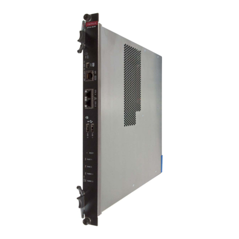
RadiSys ATCA-4616 Service manual

RadiSys
RadiSys PM6165B ONT User manual

RadiSys
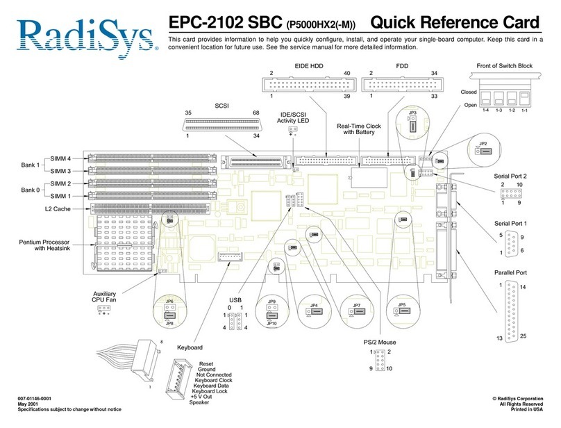
RadiSys EPC-2102 P5000HX2 Series Reference guide

RadiSys
RadiSys EPC-9 Application guide

RadiSys
RadiSys PROCELERANT CE915GMA User manual

RadiSys
RadiSys EPC-3311 Application guide

RadiSys
RadiSys ES4001G ONT User manual

RadiSys
RadiSys EPC-31 Application guide

RadiSys
RadiSys EPC-3307 Application guide