FinMInstallationGuide Release4.5.25 i
TableofContents
Chapter1:Introduction
1.1ScopeofthisDocument ...................................................................................................... 1‐1
1.2TransportationFiberinMotionOverview ............................................................................ 1‐1
1.2.1MajorComponents...................................................................................................... 1‐4
TBS...................................................................................................................1‐4
TBS antennas.....................................................................................................1‐4
TMU..................................................................................................................1‐5
TMU antennas....................................................................................................1‐6
ISU ...................................................................................................................1‐6
OSU ..................................................................................................................1‐7
GSU ..................................................................................................................1‐8
1.2.2Accessories .................................................................................................................. 1‐8
Lightning Protection Unit (LPU) ...........................................................................1‐8
PoE...................................................................................................................1‐9
1.2.3Synchronization........................................................................................................... 1‐9
1.3Features............................................................................................................................. 1‐10
1.3.1General...................................................................................................................... 1‐10
1.3.2MobilityCapabilities.................................................................................................. 1‐10
1.3.3OnboardMobileUnits ............................................................................................... 1‐10
1.4DocumentNotifications .................................................................................................... 1‐10
Chapter2:SiteInstallation
2.1ScopeofThisChapter.......................................................................................................... 2‐1
2.2Wayside............................................................................................................................... 2‐1
2.2.1Overview ..................................................................................................................... 2‐1
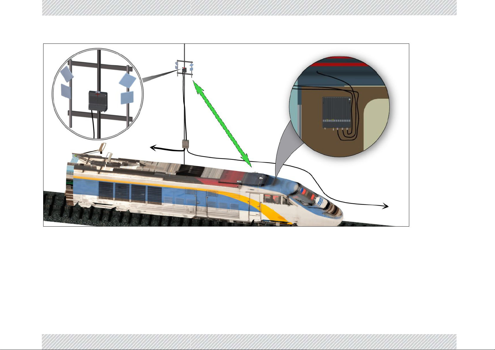
General Mounting Arrangement...........................................................................2‐1
Power................................................................................................................2‐3
Minimum Recommended Distances......................................................................2‐3
2.2.2TBSMounting.............................................................................................................. 2‐4
TBS Mounting on a Vertical Pole..........................................................................2‐6
TBS Mounting on a Horizontal Pole......................................................................2‐9
TBS mounting on a wall....................................................................................2‐13
2.2.3PoEDevicesfortheTBS ............................................................................................. 2‐16
2.2.4TBSAntennas ............................................................................................................ 2‐17
TBS Antenna Mounting on a Vertical Pole...........................................................2‐17
TBS Antenna Mounting on a Horizontal Pole.......................................................2‐20
TBS Antenna Mounting on a Wall ......................................................................2‐21
TBS Antenna Mounting Kit Adaptor....................................................................2‐21
2.2.5TBSExternalConnections .......................................................................................... 2‐24
2.2.6SynchronizationUnits................................................................................................ 2‐25
Indoor Synchronization Unit (ISU) .....................................................................2‐25
Outdoor Synchronization Unit (OSU)..................................................................2‐26
GSU ................................................................................................................2‐27
2.2.7ExternalGPSAntenna ............................................................................................... 2‐28
2.2.8LightningProtectionUnit(LPU)................................................................................. 2‐29
2.2.9Waterproofing........................................................................................................... 2‐32
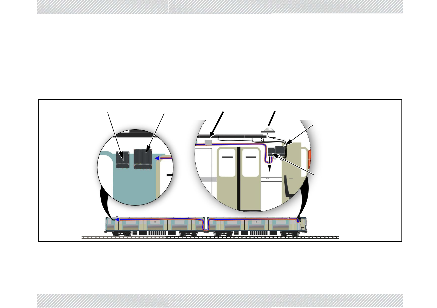
2.3On‐board ...........................................................................................................................2‐33
2.3.1Overview ................................................................................................................... 2‐33
General Guidelines ...........................................................................................2‐33
Power..............................................................................................................2‐33
General Mounting Arrangement.........................................................................2‐33
2.3.2TMUMounting.......................................................................................................... 2‐34