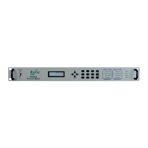
Radyne MM200 User manual

MM200
High Speed
Microwave Modem
Installation and Operation Manual
TM086 - Rev. 4.1
Comtech EF Data •2114 W 7th St. •Tempe, AZ 85281 •(480) 333-2200 •Fax: (480) 333-2540 •www.comtechefdata.com


MM200 High-Speed Microwave Modem Warranty Policy
TM086 - Rev. 4.1
iii
Warranty Policy
WP
Comtech EF Data products are warranted against defects in material and workmanship for a period of two
years from the date of shipment. During the warranty period, Comtech EF Data will, at its option, repair or
replace products that prove to be defective.
For equipment under warranty, the owner is responsible for freight to Comtech EF Data and all related
customs, taxes, tariffs, insurance, etc. Comtech EF Data is responsible for the freight charges only for
return of the equipment from the factory to the owner. Comtech EF Data will return the equipment by the
same method (i.e., Air, Express, Surface) as the equipment was sent to Comtech EF Data.
All equipment returned for warranty repair must have a valid RMA number issued prior to return and be
marked clearly on the return packaging. Comtech EF Data strongly recommends all equipment be returned
in its original packaging.
Comtech EF Data Corporation’s obligations under this warranty are limited to repair or replacement of failed
parts, and the return shipment to the buyer of the repaired or replaced parts.
Limitations of Warranty
The warranty does not apply to any part of a product that has been installed, altered, repaired, or misused
in any way that, in the opinion of Comtech EF Data Corporation, would affect the reliability or detracts from
the performance of any part of the product, or is damaged as the result of use in a way or with equipment
that had not been previously approved by Comtech EF Data Corporation.
The warranty does not apply to any product or parts thereof where the serial number or the serial number of
any of its parts has been altered, defaced, or removed.
The warranty does not cover damage or loss incurred in transportation of the product.
The warranty does not cover replacement or repair necessitated by loss or damage from any cause beyond
the control of Comtech EF Data Corporation.
The warranty does not cover any labor involved in the removal and or reinstallation of warranted equipment
or parts on site, or any labor required to diagnose the necessity for repair or replacement.
The warranty excludes any responsibility by Comtech EF Data Corporation for incidental or consequential
damages arising from the use of the equipment or products, or for any inability to use them either separate
from or in combination with any other equipment or products.
A fixed charge established for each product will be imposed for all equipment returned for warranty repair
where Comtech EF Data Corporation cannot identify the cause of the reported failure.
Exclusive Remedies
Comtech EF Data Corporation’s warranty, as stated is in lieu of all other warranties, expressed, implied, or
statutory, including those of merchantability and fitness for a particular purpose. The buyer shall pass on to
any purchaser, lessee, or other user of Comtech EF Data Corporation’s products, the aforementioned
warranty, and shall indemnify and hold harmless Comtech EF Data Corporation from any claims or liability
of such purchaser, lessee, or user based upon allegations that the buyer, its agents, or employees have
made additional warranties or representations as to product preference or use.
The remedies provided herein are the buyer’s sole and exclusive remedies. Comtech EF Data shall not be
liable for any direct, indirect, special, incidental, or consequential damages, whether based on contract, tort,
or any other legal theory.
Warranty Repair Return Procedure

Warranty Policy MM200 High-Speed Microwave Modem
iv TM086 - Rev. 4.1
iv
Before a warranty repair can be accomplished, a Repair Authorization must be received. It is at this time
that Comtech EF Data will authorize the product or part to be returned to the Comtech EF Data facility or if
field repair will be accomplished. The Repair Authorization may be requested in writing or by calling:
Comtech EF Data Corporation
2114 W 7th Street.
Tempe, Arizona 85281 (USA)
ATTN: Customer Support
Phone: (480) 333-2200
Fax: (480) 333-2540
Any product returned to Comtech EF Data for examination must be sent prepaid via the means of
transportation indicated as acceptable to Comtech EF Data. Return Authorization Number must be clearly
marked on the shipping label. Returned products or parts should be carefully packaged in the original
container, if possible, and unless otherwise indicated, shipped to the above address.
Non-Warranty Repair
When a product is returned for any reason, Customer and its shipping agency shall be responsible for all
damage resulting from improper packing and handling, and for loss in transit, not withstanding any defect or
nonconformity in the product. By returning a product, the owner grants Comtech EF Data permission to
open and disassemble the product as required for evaluation. In all cases, Comtech EF Data has sole
responsibility for determining the cause and nature of failure, and Comtech EF Data’s determination with
regard thereto shall be final.

MM200 High-Speed Microwave Modem Preface
TM086 - Rev. 4.1 v
Preface
P
This manual provides installation and operation information for the Radyne RCS20 M:N
Redundancy Switch. This is a technical document intended for use by engineers, technicians,
and operators responsible for the operation and maintenance of the RCS20.
Conventions
Whenever the information within this manual instructs the operator to press a pushbutton switch
or keypad key on the Front Panel, the pushbutton or key label will be shown in "less than" (<) and
"greater than" (>) brackets. For example, the Reset Alarms Pushbutton will be shown as
<RESET ALARMS>, while a command that calls for the entry of a ‘7’ followed by ‘ENTER’ Key will
be represented as <7,ENTER>.
Cautions and Warnings
A caution icon indicates a hazardous situation that if not avoided, may result in minor or moderate
injury. Caution may also be used to indicate other unsafe practices or risks of property damage.
A warning icon indicates a potentially hazardous situation that if not avoided, could result in death
or serious injury.
A note icon identifies information for the proper operation of your equipment, including helpful
hints, shortcuts, or important reminders.
Trademarks

Preface MM200 High-Speed Microwave Modem
TM086 - Rev. 4.1
vi
Product names mentioned in this manual may be trademarks or registered trademarks of their
respective companies and are hereby acknowledged.
Copyright
2008, Comtech EF Data This manual is proprietary to Comtech EF Data and is intended for the
exclusive use of Comtech EF Data’s customers. No part of this document may in whole or in part,
be copied, reproduced, distributed, translated or reduced to any electronic or magnetic storage
medium without the express written consent of a duly authorized officer of Comtech EF Data
Disclaimer
This manual has been thoroughly reviewed for accuracy. All statements, technical information,
and recommendations contained herein and in any guides or related documents are believed
reliable, but the accuracy and completeness thereof are not guaranteed or warranted, and they
are not intended to be, nor should they be understood to be, representations or warranties
concerning the products described. Comtech EF Data assumes no responsibility for use of any
circuitry other than the circuitry employed in Comtech EF Data systems and equipment.
Furthermore, since Comtech EF Data is constantly improving its products, reserves the right to
make changes in the specifications of products, or in this manual at any time without notice and
without obligation to notify any person of such changes.
Record of Revisions
Revision
Level
Date Reason for Change
1.0 6-16-00 New Release.
2.0 4-19-01 Revised and reformatted manual.
3.0 5-4-01 Revised User Interfaces Section.
3.1 6-4-01 Revised Electrical Interfaces Section.
3.2 10-9-01 Revised the Detailed Command Descriptions Section.
3.3
12-11-01
Revised Electrical Interfaces Section.
3.4 1-8-02 Added MIB.
4.0 3-27-03 Revised and Reformatted Technical Manual.
4.1 12-18-06 Revised and Reformatted Technical Manual
Comments or Suggestions Concerning this Manual
Comments or suggestions regarding the content and design of this manual are appreciated.
To submit comments, please contact the Comtech EF Data Corporation Customer Service
Department.

MM200 High-Speed Microwave Modem Table of Contents
TM086 - Rev. 4.1 vii
Table of Contents
ToC
Warranty Policy............................................................................................................iii
Preface...........................................................................................................................v
Conventions___________________________________________________________v
Cautions and Warnings __________________________________________________v
Trademarks ___________________________________________________________ v
Copyright ____________________________________________________________ vi
Record of Revisions____________________________________________________ vi
Comments or Suggestions Concerning this Manual ___________________________ vi
Section 1 - Introduction.............................................................................................1-1
1.0 Description ______________________________________________________ 1-1
Section 2 - Installation...............................................................................................2-1
2.1 Unpacking_______________________________________________________ 2-1
2.2 Removal and Assembly ____________________________________________ 2-2
2.3 Mounting Considerations ___________________________________________ 2-2
2.4 Modem Checkout _________________________________________________ 2-2
2.4.1 Initial Power-Up _________________________________________________ 2-3
Section 3 - Theory of Operation................................................................................3-1
3.0 Theory of Operation _______________________________________________ 3-1
3.1 Signal Flow ______________________________________________________ 3-1
3.1.1 Interfaces______________________________________________________ 3-1
3.1.2 Data Mux ______________________________________________________ 3-2
3.1.3 RF Modulators __________________________________________________ 3-3
3.1.4 RF Demodulators________________________________________________ 3-3
3.1.5 Diversity (Option) ________________________________________________ 3-3
3.2 Start-Up Procedures_______________________________________________ 3-3
3.2.1 Initial Start-up Procedure__________________________________________ 3-3

Table of Contents MM200 High-Speed Microwave Modem
TM086 - Rev. 4.1
viii
3.2.2 Sample Setups__________________________________________________ 3-4
3.2.2.1 Transmitting G.703 T3 From Interface Slot 3 (other interfaces disabled) ___ 3-4
3.2.2.2 Transmitting STM-1 From Interface Slot 1 (other interfaces disabled) _____ 3-4
3.2.3 Hardware Reset_________________________________________________ 3-4
3.3 Calculating 3 dB Bandwidth of MM200 Modulated Carrier __________________ 3-5
3.4 Input Level ______________________________________________________ 3-5
Section 4 -User Interfaces.......................................................................................4-1
4.0 User Interfaces ___________________________________________________ 4-1
4.1 Front Panel User Interface __________________________________________ 4-1
4.1.1 Front Panel LCD Display __________________________________________ 4-2
4.1.2 Cursor Control Arrows ____________________________________________ 4-2
4.1.3 Front Panel Keypad______________________________________________ 4-2
4.1.4 Front Panel LED Indicators ________________________________________ 4-3
4.1.5 Parameter Setup ________________________________________________ 4-3
4.2 Front Panel Control Screen Menus____________________________________ 4-4
4.3 Level 2 Menu Screens _____________________________________________ 4-4
4.3.1 Main Menu Screens______________________________________________ 4-4
4.3.2 MODULATOR (menu) ____________________________________________ 4-5
4.3.3 DEMODULATOR (menu)__________________________________________ 4-6
4.3.4 REPEATER (Menu) ______________________________________________ 4-8
4.3.4 APC (Menu) ____________________________________________________ 4-8
4.3.5 TX INTERFACE (Menu)___________________________________________ 4-9
4.3.6 RX INTERFACE (Menu) _________________________________________ 4-10
4.4 All Level Menu Screens ___________________________________________ 4-12
4.4.1 Main Menu Screens_____________________________________________ 4-12
4.4.2 MODULATOR (menu) ___________________________________________ 4-12
4.4.3 DEMODULATOR (menu)_________________________________________ 4-13
4.4.4 REPEATER (menu)_____________________________________________ 4-17
4.3.4 APC (Menu) ___________________________________________________ 4-17
4.4.5 TX INTERFACE (Menu)__________________________________________ 4-17
4.4.6 RX INTERFACE (Menu) _________________________________________ 4-20
4.4.7 MONITOR (Menu) ______________________________________________ 4-21
4.4.8 ALARMS (Menu) _______________________________________________ 4-24
4.4.8.1 Active Alarms ________________________________________________ 4-24

MM200 High-Speed Microwave Modem Table of Contents
TM086 - Rev. 4.1
ix
4.4.8.2 Latched Alarms_______________________________________________ 4-28
4.4.8.3 Clear Alarms_________________________________________________ 4-28
4.4.9 SYSTEM (Menu) _______________________________________________ 4-28
4.4.10 TEST (Menu) _________________________________________________ 4-30
4.5 Remote Port User Interface ________________________________________ 4-30
4.5.1 Protocol Structure ______________________________________________ 4-31
4.5.2 Protocol Wrapper_______________________________________________ 4-31
4.5.3 Frame Description and Bus Handshaking ____________________________ 4-33
4.5.4 Global Response Operational Codes _______________________________ 4-34
4.5.5 Collision Avoidance _____________________________________________ 4-36
4.5.6 Software Compatibility___________________________________________ 4-37
4.5.7 RLLP Summary ________________________________________________ 4-38
4.6 Simple Network Management Protocol (SNMP)_________________________ 4-38
4.7 The Management Information Base (MIB) _____________________________ 4-38
4.8 Directory _____________________________________________________ 4-38
4.9 Mgmt ______________________________________________________ 4-39
4.10 Experimental _________________________________________________ 4-39
4.11 Private _____________________________________________________ 4-39
4.12 Terminal Port User Interface_______________________________________ 4-40
4.13 Modem Configuration ____________________________________________ 4-40
4.14 Connecting the Terminal__________________________________________ 4-40
4.15 SNMP Option __________________________________________________ 4-42
4.16 Network Configuration ___________________________________________ 4-42
4.17 Terminal Screens _______________________________________________ 4-42
4.18 Logging on and Passwords________________________________________ 4-43
4.19 Exiting SNMP Configuration _______________________________________ 4-44
4.20 Logging On ____________________________________________________ 4-44
4.21 Changing the Logon Password_____________________________________ 4-44
4.22 Logging Off____________________________________________________ 4-45
4.23 Changing Your Authentication Password _____________________________ 4-45
4.24 Changing Your Privacy Password __________________________________ 4-45
4.25 Modem MM200 High-Speed Microwave Modem Ethernet Address_________ 4-46
4.26 Modem IP Address ______________________________________________ 4-46
4.27 Server Ethernet Address__________________________________________ 4-46
4.28 Server IP Address_______________________________________________ 4-46

Table of Contents MM200 High-Speed Microwave Modem
TM086 - Rev. 4.1
x
4.29 Server Host Name ______________________________________________ 4-46
4.30 Router IP Address_______________________________________________ 4-47
4.31 IP Address Mask________________________________________________ 4-47
4.32 Boot Mode (Optional) ____________________________________________ 4-47
4.33 Community ____________________________________________________ 4-47
4.34 Trap Type and Trap Hosts ________________________________________ 4-47
4.35 Trace Mode____________________________________________________ 4-48
4.36 SNMP V1 & 2 Access View________________________________________ 4-48
4.37 Key Generation Mode____________________________________________ 4-48
4.38 Context Engine ID_______________________________________________ 4-48
4.41 Connect the Ethernet Cable _______________________________________ 4-49
4.42 Ping Program __________________________________________________ 4-50
4.43 SNMP Test ____________________________________________________ 4-51
Section 5 - Electrical Interfaces ................................................................................5-1
5.0 MM200 Connections_______________________________________________ 5-1
5.1 Power __________________________________________________________ 5-1
5.1.1 AC Power______________________________________________________ 5-1
5.1.2 DC Power______________________________________________________ 5-1
5.2 Alarm Port_______________________________________________________ 5-2
5.3 Terminal Port (I/O) ________________________________________________ 5-3
5.4 Remote Port (I/O) _________________________________________________ 5-3
5.4.1 Remote Port Cabling for a Standard Computer RS-232 COM Port _________ 5-4
5.5 Ethernet Interface (I/O)_____________________________________________ 5-5
5.6 TX RF Port (Output) _______________________________________________ 5-5
5.7 RX RF Port (Input) ________________________________________________ 5-5
5.8 External Reference (Input) __________________________________________ 5-5
5.9 Interface Slots 1 Through 4 _________________________________________ 5-6
5.10 High-Speed G.703/DS3, E3, STS-1 Rear Panel Interface _________________ 5-6
5.10.1 G.703 OUT Female BNC Connector (J15) ___________________________ 5-6
5.10.2 CLK IN Female BNC Connector (J16)_______________________________ 5-6
5.10.3 G.703 IN Female BNC Connector (J17) _____________________________ 5-6
5.11 Overhead/DS0 Audio Rear Panel Interface ____________________________ 5-7
5.11.1 DS01 15-Pin Female HD ‘D’ Sub Connector (J7) ______________________ 5-8
5.11.2 DS02 15-pin female HD ‘D’ sub connector (J8)________________________ 5-8

MM200 High-Speed Microwave Modem Table of Contents
TM086 - Rev. 4.1
xi
5.11.3 DS03 15-pin female HD ‘D’ sub connector (J9)________________________ 5-8
5.11.4 DS04 15-pin female HD ‘D’ sub connector (J10)_______________________ 5-8
5.11.5 DS05 15-pin female HD ‘D’ sub connector (J11)_______________________ 5-8
5.11.6 DS06 15-pin female HD ‘D’ sub connector (J12)_______________________ 5-8
5.11.7 DS07 15-pin female HD ‘D’ sub connector (J13)_______________________ 5-9
5.11.8 DS08 15-pin female HD ‘D’ sub connector (J14)_______________________ 5-9
5.12 Optical/OC3 STM-1 Rear Panel Interface _____________________________ 5-9
5.12.1 ELEC OUT Female BNC Connector (J15) ___________________________ 5-9
5.12.2 ELEC IN Female BNC Connector (J16)______________________________ 5-9
5.12.3 OPTICAL IN SC Connector (J17) __________________________________ 5-9
5.12.4 Optical Out SC Connector (J18) ___________________________________ 5-9
5.12.5 REF OUT Female BNC Connector (Optional) (J19) ____________________ 5-9
5.12.6 REF IN Female BNC Connector (Optional) (J20) ______________________ 5-9
5.13 ASI Rear Panel Interface _________________________________________ 5-10
5.13.1 ASI OUT Female BNC Connector (J15) ____________________________ 5-10
5.13.2 ASI IN Female BNC Connector (J16) ______________________________ 5-10
5.14 Wayside G.703/T1, E1 Rear Panel Interface __________________________ 5-10
5.14.1 IN Female BNC Connector (J15)__________________________________ 5-10
5.14.2 OUT Female BNC Connector (J16)________________________________ 5-11
5.14.3 BALANCED 15-pin female ‘D’ sub connector ________________________ 5-11
5.14.4 CLK OUT (J17) _______________________________________________ 5-11
5.14.5 CLK IN Female BNC Connector (J18)______________________________ 5-11
5.15 Parallel RS-422/DVB, M2P________________________________________ 5-11
5.15.1 PARALLEL TX 25-pin female ‘D’ sub connector (J15) _________________ 5-12
5.15.2 PARALLEL RX 25-pin female ‘D’ sub connector (J16) _________________ 5-13
5.15.3 CLK IN (J17) _________________________________________________ 5-13
5.15.4 CLK IN Female BNC Connector (J18)______________________________ 5-13
5.16 Parallel LVDS/DVB, M2P _________________________________________ 5-14
5.16.1 PARALLEL TX 25-pin female ‘D’ sub connector (J15) _________________ 5-14
5.16.2 PARALLEL RX 25-pin female ‘D’ sub connector (J16) _________________ 5-15
5.16.3 CLK IN (J17) _________________________________________________ 5-15
5.16.4 CLK IN Female BNC Connector (J18)______________________________ 5-16
5.17 SMPTE/310M Rear Panel Interface _________________________________ 5-16
5.17.1 EXT CLK (J15)________________________________________________ 5-16
5.17.2 SMPTE IN Female BNC Connector (J16) ___________________________ 5-16

Table of Contents MM200 High-Speed Microwave Modem
TM086 - Rev. 4.1
xii
Section 6 - Maintenance and Troubleshooting ........................................................6-2
6.0 Periodic Maintenance ______________________________________________ 6-2
6.1 Maintenance Philosophy____________________________________________ 6-2
6.2 Customer Service _________________________________________________ 6-2
6.3 Troubleshooting __________________________________________________ 6-3
Section 7 - Technical Specifications ........................................................................7-1
7.0 Introduction______________________________________________________ 7-1
7.1 Specifications ____________________________________________________ 7-1
7.2 Options _________________________________________________________ 7-1
7.3 Optional Data Interfaces____________________________________________ 7-2
7.4 Optional Overhead Interfaces________________________________________ 7-2
Appendix A - Remote RLLP......................................................................................A-1
A.1 MM200 Opcode Command Set ______________________________________ A-1
A.2 Modem Command Set _____________________________________________ A-1
A.3 Detailed Command Descriptions _____________________________________ A-4
Appendix B - SNMP MIB ...........................................................................................B-1
Glossary.....................................................................................................................G-1

MM200 High-Speed Microwave Modem Introduction
TM086 - Rev. 4.1 1-1
Introduction
1
1.0 Description
The Radyne MM200 Microwave Modem is a high-speed, multi data rate Modulator/Demodulator.
It is a single rack digital modem for point-to-point or point-to-multipoint communication links and is
ideal for microwave link upgrades or retrofits.
The MM200 utilizes a proprietary matrix modulation format that provides maximum bandwidth
efficiency and data rates up to 176 Mbps (200 Mbps optional). Increased performance is
achieved in multi-path or fading environments over conventional QAM modulation.
The MM200 offers a large variety of interfaces such as T3, E3, STS1, DVB SPI, DVB ASI,
OC3/STM-1, T1, E1, E2, 10Base T, and others.
Figure 1-1. MM200 Microwave Modem

Introduction MM200 High-Speed Microwave Modem
1-2 TM086 - Rev. 4.1

MM200 High-Speed Microwave Modem Installation
TM086 - Rev. 4.1 2-1
Installation
2
2.0 Installation Requirements
The MM200 is designed to be installed within any standard 19-inch equipment cabinet or rack,
and requires 2 rack unit (RU) mounting spaces (3.5 inches) vertically and 19 inches of depth.
Including cabling, a minimum of 20 inches of rack depth is required. The rear panel of the MM200
is designed to have power enter from the left and IF cabling enter from the right when viewed from
the rear of the unit. Data and control cabling can enter from either side although they are closer to
the center. The unit can be placed on a table or suitable surface if required.
There are no user-serviceable parts or configuration settings located
inside the MM200 chassis. There is a potential shock hazard internally at
the power supply module. DO NOT open the MM200 chassis under any
circumstances.
Before initially applying power to the unit, it is a good idea to disconnect
the transmit output from the operating station equipment. This is
especially true if the current MM200 configuration settings are unknown,
where incorrect setting could disrupt existing communications traffic.
The MM200 contains a Lithium Battery. DANGER OF EXPLOSION exists if
the battery is incorrectly replaced. Replace only with the same or
equivalent type recommended by the manufacturer. Dispose of used
batteries in accordance with manufacturers instructions
2.1 Unpacking
The MM200 Modem was carefully packaged to avoid damage and should arrive complete with the
following items for proper installation:
MM200 Unit
Prime power connection
Installation and Operation Manual

Installation MM200 High-Speed Microwave Modem
2-2 TM086 - Rev. 4.1
2.2 Removal and Assembly
If using a knife or cutting blade to open the carton, exercise caution to ensure that the blade does
not extend into the carton, but only cuts the tape holding the carton closed. Carefully unpack the
unit and ensure that all of the above items are in the carton. If the Primary AC power available at
the installation site requires a different power cord/AC connector, then arrangements to receive
the proper device will be necessary before proceeding with the installation.
The MM200 modem is shipped fully assembled and does not require removal of the covers for
any purpose in installation. Should the power cable AC connector be of the wrong type for the
installation, either the cable or the power connector end should be replaced. The power supply
itself is designed for universal application using from 100 to 240 VAC, 50-60 Hz, 1A or 37 – 75
VDC @ 4A.
2.3 Mounting Considerations
When mounted in an equipment rack, adequate ventilation must be provided. The MM200 draws
air in from the left hand side and exhausts from the right rear and side (as viewed from the front).
Do not install the unit in closed locations where this airflow will be restricted. The exhaust air must
be allowed to vent away from the unit and not be allowed to flow back into the air input. The
ambient temperature in the rack should be between 0°and 50°C, and held constant for best
equipment operation. The air available to the rack should be clean and relatively dry
Do not mount the MM200 in an unprotected outdoor location where there is direct contact with
rain, snow, wind or sun. The MM200 is designed for indoor applications only.
The only tools required for rack mounting the MM200 is a set of four rack mounting screws and
an appropriate screwdriver. Rack mount brackets are an integral part of the cast front bezel of the
unit and are not removable.
Shielded cables with the shield terminated to the conductive backshells are required in order to
meet EMC directives. Cables with insulation flammability ratings of 94 VO or better are required
in order to meet low voltage directives.
2.4 Modem Checkout
The following descriptions assume that the MM200 is installed in a suitable location with prime
power and supporting equipment available.

MM200 High-Speed Microwave Modem Installation
TM086 - Rev. 4.1 2-3
2.4.1 Initial Power-Up
Before initial power up of the MM200, it is a good idea to disconnect the
transmit output from the operating ground station equipment. This is
especially true if the current modem configuration settings are unknown,
where incorrect setting could disrupt existing communications traffic.
New units from the factory are normally shipped in a default
configuration which includes setting the transmit carrier off.
Turn the unit ‘ON’ by applying power (DC versions), or placing the rear panel switch (above the
power entry connector) to the ‘ON’ position (AC versions). Upon initial and subsequent power-
ups, the MM200 microprocessor will test itself and several of its components before beginning its
main monitor/control program. These power-up diagnostics show no results if successful.

Installation MM200 High-Speed Microwave Modem
2-2 TM086 - Rev. 4.1

MM200 High-Speed Microwave Modem Theory of Operation
TM086 - Rev. 4.1 3-1
Theory of Operation
3
3.0 Theory of Operation
The MM200 Microwave Modem is a highly flexible platform for the transmission of high-speed
data across links such as microwave and cable. The 2 RU-rack mount unit can be supplied in
many different configurations and was designed to be expanded in the field to meet new and
changing operating conditions. Available in Duplex and Simplex Configurations, the unit can be
optioned with up to four industry standard interfaces in any combination, Diversity (requires two
chassis), maximum rates of 50, 100, 150, 175, and 200 Mbps, and world standard AC or DC
prime power.
The fully configured MM200 includes a data multiplexer/demultiplexer for interfacing to multiple
data sources, a modulator, and a demodulator. The MM200 is capable of data rates up to
200 Mbps at any of six different Quadrature Amplitude Modulation (QAM) schemes including
QAM256 (optional). The unique modulation/demodulation scheme uses multiple carriers to slow
the modulated symbol rate to up to four times slower than conventional modems. The lower
symbol rate is inherently more resilient to the multipath environment common to microwave
systems. An extremely powerful equalizer, working at the lower symbol rate, removes multipath
and is coupled with Reed Solomon Noise Reduction System to form a robust, reliable
communications link. Additionally, two receivers can be optioned with diversity cards. The two
chassis are then coupled via a high-speed data link to allow the automatic hitless switching to the
receiver with no errors. This feature can be used for standard path redundancy on long links or to
improve the capacity (via an increase in modulation mode) of an existing link. Refer to Figure 3-1
for operational block diagram.
3.1 Signal Flow
3.1.1 Interfaces
The transmit customer data interface consists of four “slots”. Each slot can accept one of a range
of industry standard interface cards including:
DVB ASI (1 to 160 Mbps)
DVB SPI (1 to 160 Mbps)
G.703 E3/DS3/STS-1
G.703 T1/E1
G.703 E2
OC3/STM-1 optical/electrical
Orderwire, 8 synchronous, 64 Kbps, RS-422 (one channel can be switched to ADPCM)
10Base T Ethernet
Data between interface slots can be Asynchronous and in any combination. Careful attention to
the maximum data rate and its relationship to bandwidth are required for the correct operating
conditions.
Some Interface Cards are capable of multiple standards such as the DS3,E3 or STS-1. These
cards can operate in any one of the standards listed. Changing to another standard simply
requires a change in the front panel configuration.

Theory of Operation MM200 High-Speed Microwave Modem
3-2 TM086 - Rev. 4.1
Figure 3-1. MM200 Microwave Modem Block Diagram
3.1.2 Data Muxiplexer
The multiplexer works on a constant output data rate. This data rate is directly related to the
symbol rate used by the modulators. The Symbol Rate is directly related to Bandwidth of the IF
carrier. The output of the multiplexer contains Reed Solomon overhead and mux/demux
overhead. The ratio between multiplexer input data and output data is 184/204. To
accommodate changes in the data rate supplied by the customer and the constant output of the
mux, the gaps are filled with null data that is later removed by the demux. Therefore, the
customer data is completely variable up to the point where the mux overflows. Variable interfaces
like the DVB ASI can take full advantage of this feature.
The single stream output of the mux is sent to a digital splitter that can have between one and
four outputs, which corresponds to the number of RF modulators installed.
Table of contents
Other Radyne Modem manuals

Radyne
Radyne OM20 User manual

Radyne
Radyne DMD50 User manual

Radyne
Radyne DMD2050 User manual

Radyne
Radyne OM20 User manual

Radyne
Radyne DMD20 LBST User manual

Radyne
Radyne DMD50 User manual

Radyne
Radyne DMD2401 IBS User manual

Radyne
Radyne DMD2050 Manual

Radyne
Radyne DMD20 LBST User manual

Radyne
Radyne DMD15 User manual