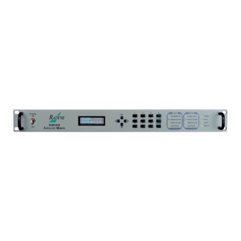
Radyne DMD2401 LB User manual

DMD2401 LB/ST
L-Band Satellite Modem
and ODU Driver
Installation and Operation Manual
TM075 - Rev. 1.3
March, 2002
- NOTICE -
2002, Radyne ComStream Corporation. This
manual may not in whole or in part be copied,
reproduced, translated or reduced to any
electronic or magnetic storage medium without
the written consent of a duly authorized officer of
Radyne ComStream Corporation.
Radyne ComStream Corporation •• 3138 E. Elwood St. •• Phoenix, AZ 85034 •• (602) 437-9620 •• Fax: (602) 437-4811


DMD2401 LB/ST L-Band Satellite Modem and ODU Driver Warranty Policy
TM075 - Rev. 1.3 iii
Radyne ComStream Corporation Warranty Policy
Warranty and Service
Radyne ComStream Corporation (Seller) warrants the items manufactured and sold by Radyne
ComStream Corporation to be free of defects in material and workmanship for a period of two (2) years
from date of shipment Radyne ComStream Corporation’s obligation under its warranty is limited in
accordance with the periods of time and all other conditions stated in all provisions of this warranty.
This warranty applies only to defects in material and workmanship in products manufactured by Radyne
ComStream Corporation. Radyne ComStream Corporation makes no guarantee whatsoever concerning
products or accessories not of its manufacture. Repair, or at Radyne ComStream Corporation’s option,
replacement of the Radyne ComStream Corporation products or defective parts therein shall be the sole
and exclusive remedy for all valid warranty claims.
Warranty Period
The applicable warranty period shall commence on the date of shipment from Radyne ComStream
Corporation’s facility to the original purchaser and extend for the stated period following the date of
shipment. Upon beginning of the applicable Radyne ComStream Corporation warranty period, all
customers’ remedies shall be governed by the terms stated or referenced in this warranty. In-warranty
repaired or replacement products or parts are warranted only for the remaining unexpired portion of the
original warranty period applicable to the repaired or replaced products or parts. Repair or replacement of
products or parts under warranty does not extend the original warranty period.
Warranty Coverage Limitations
The following are expressly not covered under warranty:
1. Any loss, damage and/or malfunction relating in any way to shipping, storage, accident, abuse,
alteration, misuse, neglect, failure to use products under normal operating conditions, failure to
use products according to any operating instructions provided by Radyne ComStream
Corporation, lack of routine care and maintenance as indicated in any operating maintenance
instructions, or failure to use or take any proper precautions under the circumstances.
2. Products, items, parts, accessories, subassemblies, or components which are expendable in
normal use or are of limited life, such as but not limited to, bulbs, fuses, lamps, glassware, etc.
Radyne ComStream Corporation reserves the right to revise the foregoing list of what is covered
under this warranty.
Warranty Replacement and Adjustment
Radyne ComStream Corporation will not make warranty adjustments for failures of products or parts which
occur after the specified maximum adjustment period. Unless otherwise agreed, failure shall be deemed to
have occurred no more than seven (7) working days before the first date on which a notice of failure is
received by Radyne ComStream Corporation. Under no circumstances shall any warranty exceed the
period stated above unless expressly agreed to in writing by Radyne ComStream Corporation.
Liability Limitations
This warranty is expressly in lieu of and excludes all other express and implied warranties, Including but
not limited to warranties of merchantability and of fitness for particular purpose, use, or applications, and
all other obligations or liabilities on the part of Radyne ComStream Corporation, unless such other
warranties, obligations, or liabilities are expressly agreed to in writing by Radyne ComStream Corporation.
All obligations of Radyne ComStream Corporation under this warranty shall cease in the event its products
or parts thereof have been subjected to accident, abuse, alteration, misuse or neglect, or which have not
been operated and maintained in accordance with proper operating instructions.
In no event shall Radyne ComStream Corporation be liable for Incidental, consequential, special or
resulting loss or damage of any kind howsoever caused. Radyne ComStream Corporation’s liability for
damages shall not exceed the payment, if any, received by Radyne ComStream Corporation for the unit or
Warranty Policy DMD2401 LB/ST L-Band Satellite Modem and ODU Driver
TM075 – Rev. 1.3iv
product or service furnished or to be furnished, as the case may be, which is the subject of claim or
dispute.
Statements made by any person, including representatives of Radyne ComStream Corporation, which are
inconsistent or in conflict with the terms of this warranty, shall not be binding upon Radyne ComStream
Corporation unless reduced to writing and approved by an officer of Radyne ComStream Corporation.
Warranty Repair Return Procedure
Before a warranty repair can be accomplished, a Repair Authorization must be received. It is at this time
that Radyne ComStream Corporation will authorize the product or part to be returned to the Radyne
ComStream Corporation facility or if field repair will be accomplished. The Repair Authorization may be
requested in writing or by calling:
Radyne ComStream Corporation
3138 E. Elwood St.
Phoenix, Arizona 85034 (USA)
ATTN: Customer Support
Phone: (602) 437-9620
Fax: (602) 437-4811
Any product returned to Radyne ComStream Corporation for examination must be sent prepaid via the
means of transportation indicated as acceptable to Radyne ComStream Corporation. Return Authorization
Number must be clearly marked on the shipping label. Returned products or parts should be carefully
packaged in the original container, if possible, and unless otherwise indicated, shipped to the above
address.
Non-Warranty Repair
When a product is returned for any reason, Customer and its shipping agency shall be responsible for all
damage resulting from improper packing and handling, and for loss in transit, not withstanding any defect
or nonconformity in the product. By returning a product, the owner grants Radyne ComStream
Corporation permission to open and disassemble the product as required for evaluation. In all cases,
Radyne ComStream Corporation has sole responsibility for determining the cause and nature of failure,
and Radyne ComStream Corporation’s determination with regard thereto shall be final.

DMD2401 LB/ST L-Band Satellite Modem and ODU Driver Record of Revisions
TM075 - Rev. 1.3 v
DMD2401 LB/ST L-Band Satellite Modem and ODU Driver
Installation and Operation Manual
TM075 – Record of Revisions
Radyne ComStream Corporation is constantly improving its products and therefore the
information in this document is subject to change without prior notice. Radyne ComStream
Corporation makes no warranty of any kind with regard to this material, Including but not limited
to the implied warranties of merchantability and fitness for a particular purpose. No responsibility
for any errors or omissions that may pertain to the material herein is assumed. Radyne
ComStream Corporation makes no commitment to update nor to keep current the information
contained in this document. Radyne ComStream Corporation assumes no responsibility for use
of any circuitry other than the circuitry employed in Radyne ComStream Corporation systems
and equipment.
Revision
Level Date Reason for Change
1.0 11-13-98 Initial Release
1.1 6-15-99 Added AUPC Data, revised the Operation Section, updated the Remote
Specification, added Appendix C, Terminal Screens.
1.2 1-25-02 Revised and reformatted Technical Manual.
1.3 3-11-02 Added new product features.

DMD2401 LB/ST L-Band Satellite Modem and ODU Driver
TM075 – Rev. 1.3vi
This Page is Intentionally Left Blank

DMD2401 LB/ST L-Band Satellite Modem and ODU Driver Table of Contents
TM075 - Rev. 1.3 vii
Table of Contents
1.0 Description______________________________________________________1-1
1.1 DMD2401 Available Options ________________________________________1-2
1.1.1 Reed-Solomon Codec ___________________________________________1-2
1.1.2 Sequential Decoding ____________________________________________1-2
1.1.3 Asynchronous Overhead Channel __________________________________1-2
1.1.4 Customized Options _____________________________________________1-3
1.1.5 8PSK Modulation _______________________________________________1-3
1.1.6 Analog AGC Voltage ____________________________________________1-3
1.1.7 Drop and Insert (D&I) ____________________________________________1-3
Section 2 – Installation
2.0 Installation Requirements __________________________________________2-1
2.1 Unpacking ______________________________________________________2-1
2.2 Removal and Assembly____________________________________________2-2
2.3 Mounting Considerations___________________________________________2-2
2.4 Modem Checkout_________________________________________________2-2
2.4.1 Initial Power-Up ________________________________________________2-2
Section 3 – Operation
3.0 Theory of Operation_______________________________________________3-1
3.1 DMD2401 LB/ST Operation_________________________________________3-1
3.2 Applications_____________________________________________________3-1
3.2.1 SCPC Point-to-Point Links ________________________________________3-1
3.2.2 SCPC Point to Multi–Point Links in a Broadcast Application ______________3-2
3.2.3 DAMA (Demand Assigned Multiple Access)___________________________3-2
3.2.4 TDMA (Time Division Multiple Access) Remote Site Application ___________3-2
3.3 DMD2401 LB/ST Initial Configuration Check____________________________3-3
3.4 DMD2401 LB/ST Automatic Uplink Power Control (AUPC Operation)_________3-3
3.5 DMD2401 LB/ST Asynchronous Overhead Operation_____________________3-4
3.5.1 Asynchronous Framing/Multiplexer Capability _________________________3-4
3.6 Standard IBS Mode _______________________________________________3-6
3.7 Asynchronous Multiplexer Mode _____________________________________3-6

Table of Contents DMD2401 LB/ST L-Band Satellite Modem and ODU Driver
viii TM075 - Rev. 1.3
3.8 ESC Backward Alarms_____________________________________________3-7
3.8.1 To Disable the ESC Backward Alarms _______________________________3-7
3.9 IDR or IBS/D&I Configuration Instructions ______________________________3-7
3.9.1 IDR Configuration (Older Modems)__________________________________3-7
3.9.2 IBS/D&I Configuration (Older Modems) ______________________________3-8
3.10 Configuring the DMD2401 for Drop and Insert _________________________3-8
3.10.1 Interface Type_________________________________________________3-9
3.10.2 Mode________________________________________________________3-9
3.10.3 Data Rate ____________________________________________________3-9
3.10.4 Terrestrial Framing - Drop Mode/Insert Mode________________________3-10
3.10.4.1 Insert Terrestrial Frame Source_________________________________3-11
3.10.5 Alarms _____________________________________________________3-11
3.11 Drop and Insert Mapping _________________________________________3-12
3.12 Loopbacks____________________________________________________3-13
3.12.1 Terrestrial Loopback___________________________________________3-13
3.12.2 Baseband Loopback___________________________________________3-14
3.12.3 IF Loopback _________________________________________________3-14
Section 4 – User Interfaces
4.0 User Interfaces __________________________________________________4-1
4.1 Front Panel User Interface__________________________________________4-1
4.1.1 Front Panel LCD Display _________________________________________4-2
4.1.2 Front Panel LED Indicators________________________________________4-2
4.1.3 Front Panel Keypad _____________________________________________4-3
4.1.4 Parameter Setup _______________________________________________4-3
4.2 Front Panel Control Menu Screens ___________________________________4-4
4.2.2 Modulator _____________________________________________________4-4
4.2.4 Interface Menu Options and Parameters _____________________________4-8
4.2.5 Monitor Menu Options and Parameters ______________________________4-9
4.2.6 Alarms Menu Options and Parameters______________________________4-10
4.2.7 System Menu Options and Parameters _____________________________4-18
4.2.8 Test Menu Options and Parameters________________________________4-20
4.3 Terminal Mode Control ___________________________________________4-21
4.3.1 Modem Terminal Mode Control____________________________________4-21
4.3.2 Modem Setup for Terminal Mode __________________________________4-21

DMD2401 LB/ST L-Band Satellite Modem and ODU Driver Table of Contents
TM075 - Rev. 1.3 ix
4.4 Remote Port User Interface________________________________________4-28
4.4.1 Protocol Structure______________________________________________4-28
4.4.2 Protocol Wrapper ______________________________________________4-29
4.4.3 Frame Description and Bus Handshaking ___________________________4-30
4.4.4 Global Response Operational Codes _______________________________4-31
4.4.5 Collision Avoidance ____________________________________________4-34
4.4.6 Software Compatibility __________________________________________4-35
4.4.7 Flow Control and Task Processing_________________________________4-36
4.4.8 RLLP Summary _______________________________________________4-37
4.4.9 DMD2401 LB/ST Opcode Command Set ____________________________4-38
4.4.10 Modulator Command Set _______________________________________4-38
4.4.11 Demodulator Command Set _____________________________________4-39
4.4.12 Module Command Set _________________________________________4-40
4.4.13 Detailed Command Descriptions _________________________________4-41
4.4.13.1 DMD2401 LB/ST Modulator____________________________________4-41
4.4.13.2 DMD2401 LB/ST Demodulator _________________________________4-63
4.4.13.3 Module Queries & Commands__________________________________4-86
4.4.13.4 Default Values Modulator _____________________________________4-90
4.4.13.5 Default Values Demodulator ___________________________________4-92
4.5 Terminal Port User Interface _______________________________________4-95
Section 5 – Electrical Interfaces
5.0 DMD2401 LB/ST Connections_______________________________________5-1
5.1 AC Power Input/Switch ____________________________________________5-1
5.2 DC Power Input/Switch ____________________________________________5-1
5.2 DMD2401 LB/ST with RS-422 Data Interface ___________________________5-1
5.2.1 RX DC POWER (J1)_____________________________________________5-1
5.2.2 TX DC POWER (J2)_____________________________________________5-1
5.2.3 TERMINAL (J3)_________________________________________________5-2
5.2.4 REMOTE (J4) __________________________________________________5-2
5.2.5 ALARM (J5) ___________________________________________________5-3
5.2.6 TX IF MON (J6)_________________________________________________5-4
5.2.7 REF MONITOR 10 MHz (J7)_______________________________________5-4
5.2.8 CLOCK (J8) ___________________________________________________5-4
5.2.9 DATA INTERFACE (J9) __________________________________________5-4

Table of Contents DMD2401 LB/ST L-Band Satellite Modem and ODU Driver
xTM075 - Rev. 1.3
5.2.9.1 RS-232 Adapter to J9 __________________________________________5-6
5.2.9.2 V.35 Adapter to J9_____________________________________________5-6
5.2.10 TX DC VOLTAGE INDICATOR____________________________________5-7
5.2.11 RX DC VOLTAGE INDICATOR ___________________________________5-7
5.3 DMD2401 LB/ST with RS-422/V.35/RS-232/Asynchronous Data Interface_____5-8
5.3.1 RX DC POWER (J1)_____________________________________________5-8
5.3.2 TX DC POWER (J2)_____________________________________________5-8
5.3.3 TERMINAL (J3)_________________________________________________5-8
5.3.4 REMOTE (J4) __________________________________________________5-8
5.3.5 ALARM (J5) ___________________________________________________5-8
5.3.6 TX IF MON (J6)_________________________________________________5-9
5.3.7 REF MONITOR 10 MHz (J7)_______________________________________5-9
5.3.8 CLOCK (J8) ___________________________________________________5-9
5.3.9 DATA INTERFACE (J9) __________________________________________5-9
5.3.10 ASYNC (J10) _________________________________________________5-9
5.3.11 TX DC VOLTAGE INDICATOR___________________________________5-10
5.3.12 RX DC VOLTAGE INDICATOR __________________________________5-10
5.4 DMD2401 LB/ST with G.703 Data Interface ___________________________5-10
5.4.1 RX DC POWER (J1)____________________________________________5-10
5.4.2 TX DC POWER (J2)____________________________________________5-11
5.4.3 TERMINAL (J3)________________________________________________5-11
5.4.4 REMOTE (J4) _________________________________________________5-11
5.4.5 ALARM (J5) __________________________________________________5-11
5.4.6 TX IF MON (J6)________________________________________________5-11
5.4.7 REF MONITOR 10 MHz (J7)______________________________________5-11
5.4.8 CLOCK (J8) __________________________________________________5-12
5.4.9 G.703 BAL (J8)________________________________________________5-12
5.4.10 SD (J9) _____________________________________________________5-12
5.4.11 RD (J10) ____________________________________________________5-12
5.4.12 TX DC VOLTAGE INDICATOR___________________________________5-12
5.4.13 RX DC VOLTAGE INDICATOR __________________________________5-13
5.5 DMD2401 LB/ST with G.703 Data Interface with Drop and Insert___________5-13
5.5.1 RX DC POWER (J1)____________________________________________5-13
5.4.2 TX DC POWER (J2)____________________________________________5-13
5.4.3 TERMINAL (J3)________________________________________________5-13

DMD2401 LB/ST L-Band Satellite Modem and ODU Driver Table of Contents
TM075 - Rev. 1.3 xi
5.4.4 REMOTE (J4) _________________________________________________5-13
5.4.5 ALARM (J5) __________________________________________________5-14
5.4.6 TX IF MON (J6)________________________________________________5-14
5.4.7 REF MONITOR 10 MHz (J7)______________________________________5-14
5.4.8 CLOCK (J8) __________________________________________________5-14
5.4.9 ESC ALARMS (J11) ____________________________________________5-14
5.4.10 ESC 8K DATA (J12)___________________________________________5-15
5.4.11 G.703 BAL (J13)______________________________________________5-16
5.4.12 SD (J14) ____________________________________________________5-16
5.4.13 DDO (J15)___________________________________________________5-16
5.4.14 IDI (J16) ____________________________________________________5-16
5.4.15 RD (J17) ____________________________________________________5-16
5.4.16 ESC 64K DATA/AUDIO (J18)____________________________________5-17
5.4.17 TX DC VOLTAGE INDICATOR___________________________________5-18
5.4.18 RX DC VOLTAGE INDICATOR __________________________________5-18
5.5 Async Port Configuration Switches __________________________________5-18
5.6 AS/3771 Daughter Card __________________________________________5-19
Section 6 – Maintenance
6.0 Periodic Maintenance _____________________________________________6-1
6.1 Troubleshooting__________________________________________________6-1
6.2 DMD2401 LB/ST Fault Philosophy ___________________________________6-1
6.2.1 Alarm Masks___________________________________________________6-2
6.2.2 Active Alarms __________________________________________________6-2
6.2.2.1 Major Alarms _________________________________________________6-2
6.2.2.2 Minor Alarms _________________________________________________6-2
6.2.2.3 Latched Alarms _______________________________________________6-2
6.3 DMD2401 LB/ST Fault Tree Matrices _________________________________6-2
6.3.1 Interpreting the Matrices__________________________________________6-4
6.3.2 IBS Fault Conditions and Actions ___________________________________6-4

Table of Contents DMD2401 LB/ST L-Band Satellite Modem and ODU Driver
xii TM075 - Rev. 1.3
Section 7 – Technical Specifications
7.0 Introduction _____________________________________________________7-1
7.1 Transmit and Receive Data Rates____________________________________7-1
7.2 Modulator Specifications ___________________________________________7-1
7.3 Demodulator/Receive Specifications__________________________________7-2
7.4 Alarms _________________________________________________________7-2
7.5 Front Panel LED Indicators _________________________________________7-2
7.6 Monitor and Control_______________________________________________7-3
7.7 Options ________________________________________________________7-3
7.8 Environmental ___________________________________________________7-3
7.9 Physical________________________________________________________7-3
7.10 Bit Error Rate (BER) Curves _______________________________________7-4
7.11 AGC Curve ____________________________________________________7-7
Section 8 – Appendices
Appendix A – Reed-Solomon Codes _____________________________________8-1
Appendix B - Carrier Control___________________________________________8-11
B.0 States ________________________________________________________8-11
B.1 Description ____________________________________________________8-11

DMD2401 LB/ST L-Band Satellite Modem and ODU Driver Introduction
TM075 - Rev. 1.3 1-1
Section 1 – Introduction
1.0 Description
The Radyne ComStream Corporation DMD2401 LB/ST L-Band Satellite Modem and Outdoor
Unit (ODU) Driver is a microprocessor-controlled Binary Phase Shift Keyed (BPSK), Quadrature
Phase Shift Keyed (QPSK), Offset Quadrature Phase Shift Keyed (OQPSK), 8PSK Trellis Coded
8-Phase Shift Keyed Modulator and Demodulator for use as part of the transmitting and
receiving ground equipment in a satellite communications system. The DMD2401 LB/ST has the
capability of delivering power and a 10 MHz Reference Signal to a Low Noise Block
Downconverter (LNB) and also to a Block Upconverter (BUC) capable of an 8-Watt Output. The
DMD2401 LB/ST Modem may be referred to as the “modem” throughout the remainder of this
document.
This versatile equipment package combines unsurpassed performance with numerous user-
friendly Front Panel programmable functions. All of the configuration, monitor and control
functions are available at the Front Panel. Operating parameters such as variable data rates,
FEC Code Rate and IF/RF Frequencies can be readily set and reconfigured from the Front Panel
by earth station operations personnel. Additionally, all functions can be accessed with a terminal
or personal computer via a serial link for complete remote monitor and control capability.
The DMD2401 LB/ST operates at data rates up to 4.375 Mbps. Selection of any data rate is
provided over the range of 9.6 Kbps to 4.375 Mbps in 1 bps steps.
The DMD2401 LB/ST is designed to perform as both ends of a satellite Single Channel Per
Carrier (SCPC) Link or as the VSAT remote site modem in a TDMA Hub System. The Modulator
and Demodulator operate independently using BPSK, QPSK, OQPSK, or 8PSK Modulation in
either SCPC or VSAT Modes.
The DMD2401 LB/ST is programmable from the Front Panel. The program menu was
specifically designed for ease of use to quickly put the modem online and for any network
changes. The modem also can be monitored and controlled through the RS-485 or RS-232
serial control channel.
Figure 1-1. DMD2401 LB/ST L-Band Satellite Modem and ODU Driver
The DMD2401 is also the ideal VSAT modem for use in a Point-to-Point Frame Relay Hybrid
Network. Other applications include FDMA, telephony, video conferencing, long-distance
learning, paging and newsgathering.
Refer to Table 1-1 for selection of any data rate that is provided over the following ranges:

Introduction DMD2401 LB/ST L-Band Satellite Modem and ODU Driver
1-2TM075 – Rev. 1.3
Table 1-1. Data Rates
FEC 1/2 2/3 3/4 7/8
BPSK 4800 bps –
1250 Kbps N/A 7200 bps –
1875 Kbps 8400 bps –
2187.5 Kbps
QPSK 9600 bps –
2500 Kbps N/A 14400 bps –
3750 Kbps 16800 bps –
4375 Kbps
OQPSK 9600 bps –
2500 Kbps N/A 14400 bps –
3750 Kbps 16800 bps –
4375 Kbps
8PSK N/A Optional N/A N/A
The DMD2401 can track and acquire a carrier over a programmable range of ±1 kHz to ±42 kHz.
Acquisition times of less than 10 seconds are typical at data rates of 64 Kbps over a range of
± 25 kHz.
To facilitate link testing, the DMD2401 incorporates built-in ‘2047’ test pattern generators with
BER measurement capability. A user-selectable terrestrial and/or satellite loopback test
capability is also provided.
For applications requiring systems redundancy, multiple DMD2401 modems may be used with
the Radyne RCS11 1:1 Redundancy Switch or the RCS20 M:N (N < 9) Redundancy Switch. A
full range of industry-standard interfaces are available for the DMD2401, DMD2401L, and
DMD2401 IBS/IDR. These include RS-232, V.35, RS-422/-449 and ITU G.703.
1.1 DMD2401 Available Options
A wide range of options are available for the DMD2401 LB/ST which include a low data rate
asynchronous serial overhead channel for remote monitor and control. A brief description of
each follows:
1.1.1 Reed-Solomon Codec
The DMD2401 can be equipped with a Reed-Solomon outer codec with an interleaver as an
optional enhancement for applications requiring Bit Error Rates of 10-10. The encoder and
decoder are completely independent and meet IESS-308/-309 Specifications. Once prepped,
this option can be installed in the field by installing four ICs into existing sockets.
Note: Custom Reed-Solomon codes are also available.
1.1.2 Sequential Decoding
The DMD2401 can also be equipped with an optionally installed sequential decoder. The
DMD2401 must be prepped for this option in the factory. Once prepped, the option can be
added by installing an IC into an existing socket. Sequential Encoding/Decoding can operate
with 1/2, 3/4, and 7/8 Rates up to data rates of 4.375 Mbps.
1.1.3 Asynchronous Overhead Channel
The DMD2401 can be equipped with optional asynchronous overhead channel capability. The
option can be added in the field by installing a single interface PC board. The overhead channel
is proportional to the data rate (Baud Rate is approximately 1/2000 of the Data Rate for Standard
IBS and up to a maximum of 19.2 Kbaud for IBS Async).

DMD2401 LB/ST L-Band Satellite Modem and ODU Driver Introduction
TM075 - Rev. 1.3 1-3
1.1.4 Customized Options
The DMD2401 may be customized for specific customer requirements. Most
modifications/customization can be accomplished by means of firmware/software modifications.
The following are examples of the types of customization available to the user:
1. Customized Data Rates.
2. Customized Scrambler/Descramblers.
3. Customized Overhead Framing Structures.
4. Customized Modulation Formats.
5. Customized Uses for Asynchronous Overhead Channel.
1.1.5 8PSK Modulation
The DMD2401 can be equipped with 8PSK Modulation capability as an add-on option. The
8PSK Option can be added by installing one IC into an existing socket.
1.1.6 Analog AGC Voltage
The DMD2401 can be equipped at the factory to produce an analog voltage equivalent to its
AGC for use in antenna controllers.
1.1.7 Drop and Insert (D&I)
The DMD2401 can be equipped at the factory with D&I as an add-on enhancement. The D&I
Functions are completely independent and can be programmed for n x 64 blocks of either T1 or
E1 Data Streams.

Introduction DMD2401 LB/ST L-Band Satellite Modem and ODU Driver
1-4TM075 – Rev. 1.3
This Page is Intentionally Left Blank

DMD2401 LB/ST L-Band Satellite Modem and ODU Driver Installation
TM075 - Rev. 1.3 2-1
Section 2 – Installation
2.0 Installation Requirements
The DMD2401 LB/ST Modem is designed to be installed within any standard 19-inch wide
equipment cabinet or rack, and requires two rack units of mounting space (3.5 inches) vertically
and 21 inches of depth. Including cabling, a minimum of 23-inches of rack depth is required.
The rear panel of the DMD2401LB/ST is designed to have power enter from the left and IF
cabling enter from the center when viewed from the rear of the modem. Data and control
cabling can enter from either side although they are closer to the right. The unit can be placed
on a table or suitable surface if required.
There are no user-serviceable parts or configuration settings located
inside the DMD2401 LB/ST Chassis. There is a potential shock hazard
internally at the Power Supply Module. DO NOT open the DMD2401 LB/ST
chassis under any circumstances.
Before initially applying power to the unit, it is a good idea to disconnect
the transmit output from the operating ground station equipment. This is
especially true if the current DMD2401 LB/ST configuration settings are
unknown, where incorrect settings could disrupt existing communications
traffic.
SHOCK HAZARD. Double-Pole/Neutral Fusing. Exercise extreme caution.
2.1 Unpacking
The DMD2401 LB/ST was carefully packaged to avoid damage and should arrive complete with
the following items for proper installation:
•DMD2401 LB/ST Modem Unit.
•Power Cord, 6-foot with applicable AC Connector.
•Installation and Operation Manual.

Installation DMD2401 LB/ST L-Band Satellite Modem and ODU Driver
2-2TM075 – Rev. 1.3
2.2 Removal and Assembly
If using a knife or cutting blade to open the carton, exercise caution to ensure that the blade does
not extend into the carton, but only cuts the tape holding the carton closed. Carefully unpack the
unit and ensure that all of the above items are in the carton. If the Prime AC power available at
the installation site requires a different power cord/AC connector, then arrangements to receive
the proper device will be necessary before proceeding with the installation.
The DMD2401 LB/ST Unit is shipped fully assembled and does not require removal of the covers
for any purpose in installation. Should the power cable AC connector be of the wrong type for
the installation, either the cable or the power connector end should be replaced. The power
supply itself is designed for universal application using from 100 to 240 VAC, 50-60 Hz, 1.0 A.
2.3 Mounting Considerations
When mounted in an equipment rack, adequate ventilation must be provided. The ambient
temperature in the rack should preferably be between 10°and 35°C, and held constant for best
equipment operation. The air available to the rack should be clean and relatively dry. Modem
units should not be placed immediately above a high heat or EMF generator to ensure the output
signal integrity and proper receive operation.
Do not mount the DMD2401 LB/ST in an unprotected outdoor location where there is direct
contact with rain, snow, wind or sun. The modem is designed for indoor applications only. The
only tools required for rack mounting the DMD2401 LB/ST is a set of four rack mounting screws
and an appropriate screwdriver. Rack mounting brackets are an integral part of the cast front
bezel of the unit and are not removable.
J1 and J2, Tx and Rx IF connectors have voltage on the ports. Exercise
care when the DMD2401 LB/ST has power applied.
2.4 Modem Checkout
The following descriptions assume that the DMD2401 LB/ST is installed in a suitable location
with prime AC power and supporting equipment available.
2.4.1 Initial Power-Up
Before initial powerup of the DMD2401 LB/ST, it is a good idea to
disconnect the transmit output from the operating ground station
equipment. This is especially true if the current modulator configuration
settings are unknown, where incorrect settings could disrupt the existing
communications traffic. New units from the factory are normally shipped
in a default configuration which includes setting the transmit carrier off.

DMD2401 LB/ST L-Band Satellite Modem and ODU Driver Installation
TM075 - Rev. 1.3 2-3
Turn the unit ‘ON’ by placing the Rear Panel Switch (located above the power entry connector) to
the ‘ON’ Position. Upon initial and subsequent power-ups, the DMD2401 LB/ST Microprocessor
will test itself and several of its components before beginning its main Monitor/Control Program.
These Power-Up Diagnostics show no results if successful. If a failure is detected, the Fault LED
will illuminate.
The initial field checkout of the modem can be accomplished from the Front Panel or in the
Terminal Mode. The Terminal Mode has the advantage of providing full screen access to all of
the modem’s parameters, but requires a separate terminal or computer running a terminal
program. The unit is placed into Terminal Mode by setting two options via the Front Panel. The
two options are the Term Baud and Emulation settings found under the System M&C Submenus.
Terminal Setup:
Baud Rate: 19.2 K (can be changed via Front Panel)
Data Bits: 8
Parity: No Parity (Fixed)
Stop Bits: 1 Stop Bit
This manual suits for next models
1
Table of contents
Other Radyne Modem manuals

Radyne
Radyne DMD20 LBST User manual

Radyne
Radyne OM20 User manual

Radyne
Radyne DMD2050 User manual

Radyne
Radyne DMD20 LBST User manual

Radyne
Radyne DMD20 LBST User manual

Radyne
Radyne DMD50 User manual

Radyne
Radyne DMD50 User manual

Radyne
Radyne OM20 User manual

Radyne
Radyne DMD2050 Manual

Radyne
Radyne DMD15 User manual