Rail-Ability Komatsu D41 Series User manual

Issue 1 Page 1 of 34 Initial Issue 19 December 2017 Engineering Manager
(
(K
KO
OM
M-
-0
00
02
2)
)
R
RA
AI
IL
L
O
OP
PE
ER
RA
AT
TI
IO
ON
NS
S
&
&
E
EM
ME
ER
RG
GE
EN
NC
CY
Y
R
RE
EC
CO
OV
VE
ER
RY
Y
P
PR
RO
OC
CE
ED
DU
UR
RE
ES
S
R
RA
AI
IL
L-
-A
AB
BI
IL
LI
IT
TY
Y
K
KO
OM
MA
AT
TS
SU
U
D
D4
41
1*
*-
-6
6
T
TR
RA
AC
CK
K
T
TY
YP
PE
E
T
TR
RA
AC
CT
TO
OR
R
Contents

Issue 1 Page 2 of 34 Initial Issue 19 December 2017 Engineering Manager
Contents
1Introduction..........................................................................................................4
2Description and Intended Use .............................................................................6
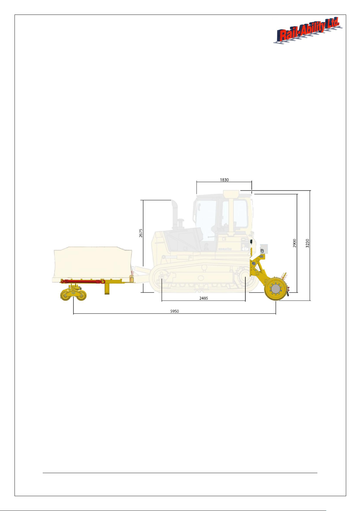
3General Dimensions............................................................................................6
4Rail Specifications ...............................................................................................6
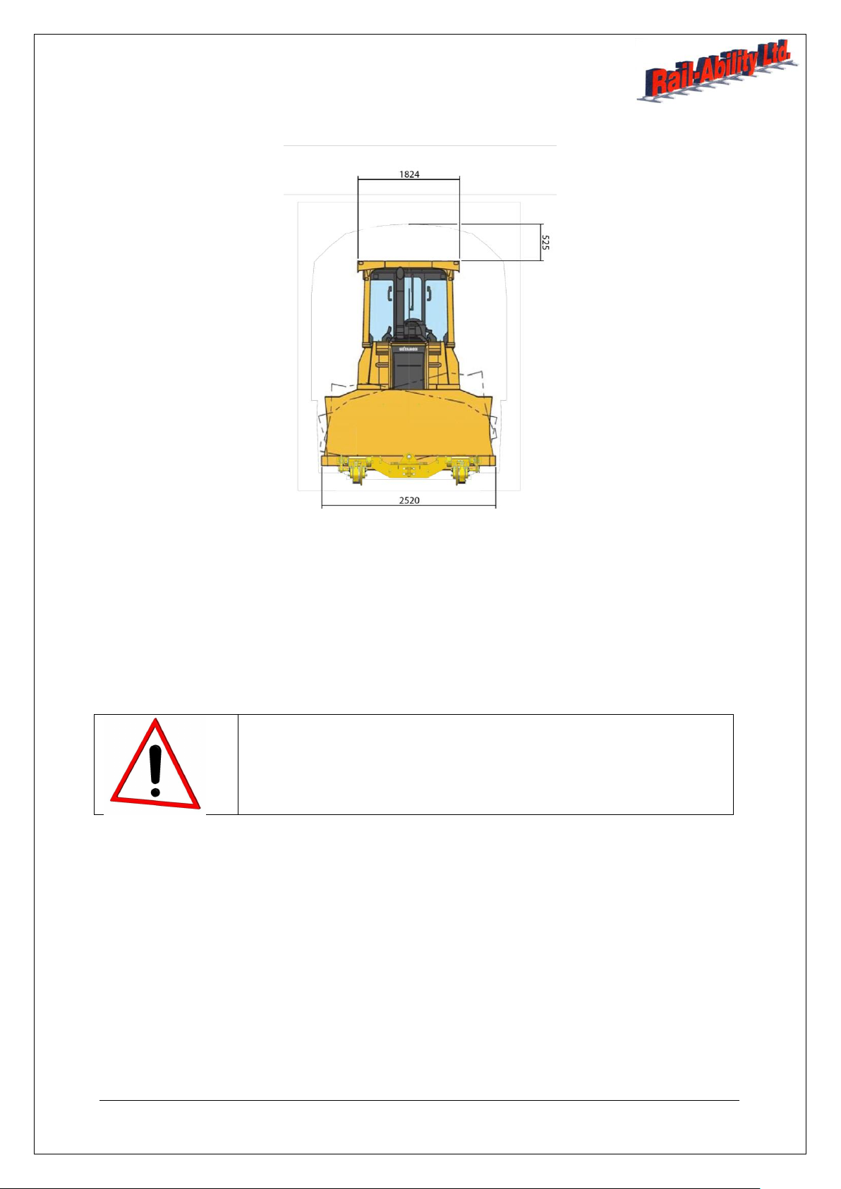
5Gauge Dimensions..............................................................................................7
6Limitations ...........................................................................................................7
7Operational Safety Precautions...........................................................................7
8Safety Rules ........................................................................................................9
8.1 General...................................................................................................................9
8.2 Electrocution Hazards.............................................................................................9
8.3 Travel Hazards .....................................................................................................10
8.4 Tip-over Hazards ..................................................................................................10
8.5 Fall Hazards..........................................................................................................11
8.6 Collision Hazards..................................................................................................11
8.7 Crushing Hazards.................................................................................................11
8.8 Explosion and Fire Hazards..................................................................................11
8.9 Burn Hazards........................................................................................................12
8.10 Bodily Injury Hazards.........................................................................................12
8.11 Lifting Hazard....................................................................................................12
8.12 Damaged or Malfunctioning Machine Hazards ..................................................12
8.13 Component Damage Hazards...........................................................................12
9Rail Safety .........................................................................................................13
9.1 General.................................................................................................................13
9.2 On/Off Track.........................................................................................................13
10 Control Layout ...................................................................................................14
11 Operating Control Principles..............................................................................15
11.1 Rail Systems .....................................................................................................15
11.2 Blade UP-DOWN/Ripper Control Lever.............................................................15
11.3 Rail Axle Deploy/Rail Drive Change-Over..........................................................15
11.4 Rail Axle Deploy................................................................................................15
11.5 Bogie Axle Deploy.............................................................................................15
11.6 Blade Rams Lock..............................................................................................15
11.7 Crawler Tracks Interlock....................................................................................16
11.8 Rail Drive Acknowledge Interlock ......................................................................17
11.9 Rail Travel.........................................................................................................17
11.10 Low Speed Selector ..........................................................................................17
12 On / Off Tracking ...............................................................................................18
13 Suggested On / Off Tracking Area Requirements..............................................19

Issue 1 Page 3 of 34 Initial Issue 19 December 2017 Engineering Manager
14 Installation of Ram Strut for Travelling On Track...............................................20
15 Travelling on the Rail.........................................................................................22
16 Bogie Handling ..................................................................................................23
17 Front Bogie Connect/Disconnect.......................................................................24
18 Emergency Off Tracking....................................................................................27
19 Rail Lights..........................................................................................................27
20 Earth Bonding Straps.........................................................................................28
21 Emergency Recovery ........................................................................................28
22 Towing...............................................................................................................31
23 After Each Use...................................................................................................33
24 Transportation....................................................................................................33
24.1 General.............................................................................................................33
24.2 Loading .............................................................................................................33
24.3 Lashing Rings ...................................................................................................34
24.4 Transit...............................................................................................................34
25 Decals................................................................................................................34
Figures
Figure 1 - Control Layout..........................................................................................14
Figure 2 - Crawler Tracks Interlock ..........................................................................16
Figure 3 - Rail Drive Acknowledge Interlock.............................................................17
Figure 4 - On / Off Tracking Area.............................................................................19
Figure 5 - Ram Strut.................................................................................................20
Figure 6 - Retaining Pins..........................................................................................21
Figure 7 - Blade Angle and Tilt Ram Stops..............................................................21
Figure 8 - Travelling on the Rail...............................................................................22
Figure 9 - Front Bogie Connection...........................................................................24
Figure 10 - Hook Locks............................................................................................25
Figure 11 - Brake Connection Hose.........................................................................25
Figure 12 - Front Bogie Disconnection.....................................................................26
Figure 13 - Earth Bonding Straps.............................................................................28
Figure 14 - Emergency Recovery.............................................................................29
Figure 15 - Brake Adjuster .......................................................................................30
Figure 16 - Centre Plug Removal.............................................................................31
Figure 17 - Centre Shaft Removal...........................................................................31
Figure 18 - Centre Shaft Extraction..........................................................................32
Figure 19 - Plug Refit ...............................................................................................32

Issue 1 Page 4 of 34 Initial Issue 19 December 2017 Engineering Manager
1 Introduction
This Operator’s Manual has been compiled for the purposes of safe operation, maintenance and
servicing of Rail-Ability components and systems.
For other operating details (e.g. Dozer vehicle, blade guidance systems, Road Rail Operations, Rail
Gear, etc.) refer to the publications listed below.
Left or right are to be with the reader sitting in the driver’s seat in the cab facing forwards, unless
otherwise stated.
Title
Part No
Rail-Ability
Operator’s Manual (this manual)
Original Instructions (English)
KOM002
Rail-Ability Rail-Reach
Parts Manual
1st Edition
GA****
Rail-Ability Service Manual
KOMDRMP001
EMI Safety Manual
27581
Manual of Responsibilities
ANSI A92.6-1990
44163
KOMATSU OPERATOR HAND BOOK
************
KOMATSU Service Manual
************
KOMATSU Parts Book
***********
Be sure the Operator’s, Safety, and Responsibilities manuals are complete, legible and located with
the machine.

Issue 1 Page 5 of 34 Initial Issue 19 December 2017 Engineering Manager
IMPORTANT
READ, UNDERSTAND AND OBEY THE CONTENTS OF THIS OPERATOR’S MANUAL BEFORE
THE OPERATION OF THIS MACHINE.
ONLY TRAINED AND AUTHORISED PERSONNEL SHALL BE PERMITTED TO OPERATE THIS
MACHINE.
THIS MACHINE IS VERY COMPLEX AND POTENTIALLY DANGEROUS. IT IS IMPORTANT THAT
BEFORE ANY USE OF THE MACHINE OCCURS, EXCEPT TRANSPORTATION AND MODULE
HANDLING, THE FOLLOWING ACTIVITIES HAVE ALL BEEN PERFORMED AND CARRIED OUT
IN THE ORDER STATED:
1. Pre-Operation Actions
2. Routine Maintenance as determined by the Pre-Operation Actions
3. Function Tests
4. Workplace Assessment
5. Operating Instructions.
THIS MANUAL SHOULD BE CONSIDERED A PERMANENT PART OF THIS MACHINE AND
SHOULD REMAIN WITH THE MACHINE AT ALL TIMES.
Should you have any questions, contact Rail-Ability Ltd:
Rail-Ability Ltd
Tollgate Drive
Tollgate industrial Estate
Stafford
ST163HS
Tel: (01785) 214747
Fax: (01785) 214717
E-Mail: mail@railability.co.uk
The Rail-Ability web site is www.railability.co.uk.

Issue 1 Page 6 of 34 Initial Issue 19 December 2017 Engineering Manager
2 Description and Intended Use
The Rail-Ability Bull Dozer machine consists of a construction bulldozer, with rail axle attachments for
use on rail by Rail-Ability Ltd. The chassis is fitted with rail gear at the rear and a detachable rail
bogie under the blade at the front to enable rail travel.
The Rail Equipment complies with the provisions of the following EC Council Directives:
Machinery 2006/42/EC
Electromagnetic Compatibility (EMC)2004/108/EC
Noise Emission in the Environment by Equipment for use Outdoors 2000/14/EC.
Guidance has also been taken from European standard EN 15746:20.
For further compliance information, refer to the EC Declaration of Conformity supplied with the OEM
machine.
3 General Dimensions
4 Rail Specifications
The machine with the rail equipment fitted has a gross weight of 14 tonnes and the front bogie has a
Tare weight of 750kg when detached from the Dozer.

Issue 1 Page 7 of 34 Initial Issue 19 December 2017 Engineering Manager
5 Gauge Dimensions
6 Limitations
For limitations of use, refer to the Engineering Compliance Certificate issued for the machine.
The use of this machine is limited to its intended use, as described above. If additional or special
applications or uses are required which are not covered by this Operator’s Manual, carefully analyse
the situation and refer to Rail-Ability Ltd for advice before proceeding.
Operational and environmental limitations of the equipment are described in the Operational Safety
Precautions section of this manual.
Safety alert symbol –used to alert personnel to potential personal injury
hazards. Obey all safety messages that follow this symbol to avoid possible
injury or death.
7 Operational Safety Precautions
All work on or near the Railway infrastructure must be carried out strictly in accordance with
Railway regulations.
Attention must be paid to Railway Group Standards and all safety precautions must be followed
at all times.
When working on electrically operated routes, be sure to observe official regulations. Always
observe minimum clearance from overhead wires.
All staff must be fully trained and assessed as competent to use this piece of equipment on
Railway Infrastructure.

Issue 1 Page 8 of 34 Initial Issue 19 December 2017 Engineering Manager
See the network rail VAB engineering acceptance certificate for additional, specific machine
limitations of use.
This manual should be used in conjunction with the operators Safe System of Work and OEM
manuals.
Modifications to the vehicle must be authorised by rail-ability and a plant acceptance body that
will issue an amended engineering conformance certificate. Failure to get approval will
invalidate the existing engineering conformance certificate.
This manual should remain with the machine at all times. All OPERATING personnel should be
aware of its location and contents.
It is important that all personnel are fully trained and familiar with the machine and that they
have read and understood the information contained within this manual before operating in the
site conditions for which the machine was designed.
Only authorised staff may start, operate or interface with the vehicle.
The user of the vehicle shall only operate the machine IN ACCORDANCE TO THIS MANUAL
and avoid overloading.
All personnel are obliged to take precautions given by the railway infrastructure manager.
Personnel are NOT permitted between moving vehicles.
The vehicle may only operate with the access adjacent to access or a line closed to all train
movements or the documented safe system of work must take account of adequate safe
clearances to adjacent lines.
The vehicle is not suitable for operation of spring loaded points.
The vehicle is not for use on live third/forth rail areas.
The vehicle is not designed to tow or propel other machines.
The machine is not designed to tow or propel rail trailers.
The machine is not designed to carry or lift loads.
The machine does not have a working mode on track. It has a travel mode only.
The machine brakes should be checked prior to each use.
Each machine function and interlock should be tested before the machine is put on track and /
or used for work.
For working in dusty environments the machine should be equipped with the optional
pressurised cab system.
Shearing, entrapment: the machine has a lot of moving parts that are impossible to protect,
therefore the operator shall always be aware of this residual risk and keep clear from the
moving parts in, particularly from the blade assembly and tracks. The operator is held
responsible not only for them self but also for those working in proximity of the machine
including any that are not authorized.

Issue 1 Page 9 of 34 Initial Issue 19 December 2017 Engineering Manager
8 Safety Rules
DANGER. FAILURE TO OBEY THE INSTRUCTIONS AND SAFETY RULES IN THIS MANUAL
MAY RESULT IN DEATH OR SERIOUS INJURY.
8.1 General
Read, understand and obey all applicable governmental regulations.
Read, understand and obey the employer’s safety rules and worksite regulations.
Comply with the employer’s, job site and governmental rules regarding use of personal
protective equipment.
Read, understand and obey the manufacturer’s instructions and safety rules, safety and
operator’s manuals and machine decals.
Learn and practice the principles of safe machine operation contained in this operator’s
manual.
Be properly trained to safely operate the machine.
Always obey national traffic regulations while driving the vehicle on roads. Be aware of the
vehicle’s overall length, width and height.
Avoid hazardous situations.
The lack of maintenance may cause damage or hurt people.
Know and understand the safety rules before going on to the next items:
Prior to use:
Always perform Pre-Operation Actions.
Always perform Function Tests.
Always perform a Workplace Inspection.
Only use the machine as it was intended:
Using the work platform for anything other than lifting personnel, along with their
tools and materials, to an aerial work site is unsafe and dangerous.
Do not engage in stunt driving or misbehave while operating the machine.
8.2 Electrocution Hazards
This machine is NOT electrically insulated and will NOT provide protection from contact with or
proximity to electrical current.
When in operation maintain the minimum safe distances from electrical conductor rails and
apparatus in accordance with the applicable regulations .

Issue 1 Page 10 of 34 Initial Issue 19 December 2017 Engineering Manager
Keep away from the machine if it contacts energised power cables / rails. Personnel on
the ground or in the cab must NOT touch or operate the machine until energised power
lines are shut off:
Do not attempt to assist someone in direct or indirect contact with the power line before
the power has been disabled as you run the risk of being electrocuted yourself.
Warn others to stay away.
Call for help.
Contact the power company to de-energize the line.
If you are in the truck cabin, stay inside without touching the vehicle body because it's
extremely hazardous to go out before the line is de-energised.
Help the electrocuted person if you know the first-aid procedures, otherwise wait for the
paramedics to arrive.
Refer to Engineering Acceptance Certificate for live OLE limitations.
Do not use the machine as a ground for welding unless the machine is equipped with the weld
line to platform option and it is properly connected.
Inspect daily for damaged cables and wires. Replace damaged items before operating.
Avoid contact with electrical terminals.
Earth bonding straps:
Straps must be in place at all times and securely fastened.
Inspect the straps daily.
Replace straps immediately if there are any signs of burning or damage.
Replace damaged straps before operating.
Check impedance levels after refitting any straps.
Avoid electrical shock from contact with battery terminals. Remove all rings, watches and other
jewellery.
8.3 Travel Hazards
Be aware of limited sight distance and blind spots when driving. Use a ‘banksman’ or machine
controller when required.
Limit travel speed according to conditions, slope, location of personnel, and any other factors,
which may cause collision.
Take care while travelling on rail, especially when the work mast is fitted.
Beware of slippery and limited traction conditions on rail. Braking distance can increase
significantly in wet or icy conditions.
8.4 Tip-over Hazards
Do not alter or disable the safety switches (e.g. limit and proximity switches).
Do not alter or disable machine components that in any way affect safety and stability.
Do not replace items critical to machine stability with items of different weight or specification. If
in doubt, contact Rail-Ability Ltd.
Do not modify or alter this machine without prior written permission from Rail-Ability Ltd.

Issue 1 Page 11 of 34 Initial Issue 19 December 2017 Engineering Manager
8.5 Fall Hazards
Always sit in the seat and fasten the seat-belt when operating the cab controls.
Always use the white steps and white handholds provided when accessing and exiting the
vehicle tracks, or cab. Never climb into the cab by other means or jump from the cab onto the
ground.
Vehicle tracks:
Take care when on the tracks (either when accessing the cab or performing inspection or
maintenance), particularly in wet or icy conditions.
Remove any loose equipment or tools that could fall off during transit or present a trip
hazard.
Clean up any oil or other fluid spillages on the deck which could create a slippery
surface.
Keep the cab clean and tidy.
Do not attempt to enter or exit the cab when the machine is moving.
8.6 Collision Hazards
Check the work area for obstructions or other possible hazards.
Do not operate the machine in the path of any other moving machinery unless precautions
have been taken to prevent any potential collision. Use a ‘banksman’ or machine controller to
alert the operator/driver when required.
Cab:
Be aware of limited sight distance and blind spots when operating the machine. Use a
‘banksman’ or machine controller when required.
Be aware of blade position and tail-swing when turning.
Take extra care when the masts are elevated at the same time.
8.7 Crushing Hazards
Keep hands and limbs away from moving parts of the machinery.
Maintain safe distances between the operator, the machine and fixed objects.
Use common sense and planning when operating the machine with a ‘banksman’ or controller
from the ground.
8.8 Explosion and Fire Hazards
Do not start the engine if you smell or detect Liquid Petroleum Gas (LPG), gasoline, diesel fuel
or other explosive substances.
Do not refuel the tank(s) when the engine is running.
Refuel the tank(s) and charge the battery only in an open, well-ventilated area away from
sparks, flames and lighted tobacco.
Do not operate the machine in hazardous locations or locations where potentially flammable or
explosive gases or particles may be present.
Do not spray ether into engines equipped with glow plugs.
Keep sparks, flames and lighted tobacco away from the batteries as batteries emit an explosive
gas.

Issue 1 Page 12 of 34 Initial Issue 19 December 2017 Engineering Manager
Do not contact the battery terminals or the cable clamps with tools that may cause sparks.
8.9 Burn Hazards
As batteries contain acid, always wear protective clothing and eye wear when working with
batteries.
Avoid spilling or contacting battery acid.
Neutralise battery acid spills with baking soda and water.
Do not expose batteries to water or rain.
8.10 Bodily Injury Hazards
Do not operate a machine with a hydraulic oil or air leak as a hydraulic leak can penetrate
and/or burn skin.
Improper contact with components under any cover will cause serious injury. Only trained
maintenance personnel should access compartments. Access by the operator is only advised
when performing a pre-operation inspection.
All compartments must remain closed and secured during operation.
Always operate the machine in a well-ventilated area to avoid carbon monoxide poisoning.
8.11 Lifting Hazard
Use the appropriate number of people and proper lifting techniques when lifting:
batteries
drawbars
tools
other removable items.
DO NOT ATTEMPT TO MANUALLY LIFT THE BLADE BOGIE.
8.12 Damaged or Malfunctioning Machine Hazards
Do not use a damaged or malfunctioning machine.
Tag and remove from service a damaged or malfunctioning machine.
8.13 Component Damage Hazards
Do not use any battery or charger greater than 24V to jump-start the host vehicle OEM engine.
Do not use the machine as a ground for welding unless the machine is equipped with the Weld
Line option and is properly connected.

Issue 1 Page 13 of 34 Initial Issue 19 December 2017 Engineering Manager
9 Rail Safety
DANGER. FAILURE TO OBEY THE INSTRUCTIONS AND SAFETY RULES IN THIS MANUAL
MAY RESULT IN DEATH OR SERIOUS INJURY.
Failure to comply with these requirements may result in severe damage to the machine and/or the rail
infrastructure.
9.1 General
All work on or near the railway infrastructure must be carried out strictly in accordance with
railway regulations.
Always observe Network Rail codes of practice.
Work must be carried out in accordance to rulebook GE/RT 8000 and all safety precautions
must be followed at all times.
Attention must be paid to Railway Group Standards and all safety precautions must be followed
at all times.
All staff must be fully trained and certified as competent to use this piece of equipment on
railway infrastructure by the owner/operator.
When working on electrically operated routes, be sure to observe official regulations. Always
observe minimum clearance from overhead wires.
Never use in 3rd and 4th rail areas.
Never use on track without a possession.
Never use on track under live OLE, ensure a relevant C Form is obtained.
Never use on track when trains are running.
Never On/Off-Track in areas with close proximity hazards such as in station platforms under/on
bridges, in tunnels or in areas with low overhead structures or line side structures.
See the Network Rail VAB Engineering Acceptance Certificate and EC Type Examination
Certificate for additional, specific machine limitations of use.
9.2 On/Off Track
Always utilise an approved On/Off-Tracking method.
Never On/Off-Track in areas with any cable connections to the rail.
Never On/Off-Track in areas with ATP loop cables either in the rail web or in the “four foot”.
Never On/Off-Track in areas with any cables cleated to the top surfaces of sleepers.
Never On/Off -rack in areas with any signalling equipment fitted in the “four foot”.

Issue 1 Page 14 of 34 Initial Issue 19 December 2017 Engineering Manager
10 Control Layout
Figure 1 - Control Layout
Note: The rail mode master switch changes the operation of the lever between rail gear
raise/lower, when not in rail mode & travel forward/reverse, when in rail mode.
Rail Mode
Master Switch
Rail Axle
Deploy / Rail
Drive Switch
Forward/reverse travel &
Rear rail gear raise/lower lever
Work
Light
Switch
Low Speed
Change
Down Switch
Horn Switch

Issue 1 Page 15 of 34 Initial Issue 19 December 2017 Engineering Manager
11 Operating Control Principles
11.1 Rail Systems
This rail axle position automatically manages the rail functions for all rail-mounted operations. When
operated, the blade controls are reassigned to operate the rail drive, rail brakes and rail axle deploy
functions. It also activates the rail navigation lights and speed restriction system. The dozer blade
shims and blade trolley lock system are all manually applied. Gauging interlocks are also maintained
by the ram shims.
11.2 Blade UP-DOWN/Ripper Control Lever
Normally this operates the blade up/dn ram or ripper up/dn ram, but in rail mode this controls the rail
axle up down and rail travel depending on which function is selected by the operator.
When the axle changeover is operated, this lever then raises and lowers the rear rail gear.
When the drive changeover is operated, and the secondary drive acknowledge button pressed, this
lever then drives the rear rail gear forwards or backwards.
Note: Rail function will only operate if the track drive lever, cab exit lock is down to isolate the crawler
travel controls.
11.3 Rail Axle Deploy/Rail Drive Change-Over
This changes between rear rail gear for raising and lowering the rear wheels and rail travel. Note that
the rail travel interlock is always active when operating the rail axle ram. The light in the switch will
illuminate when the rail gear is fully deployed for travel.
11.4 Rail Axle Deploy
To deploy the rear rail axle, ensure that the rail master switch is on and then press and hold the rail
axle deploy switch position and operate the blade raise lower lever to raise and lower the rail drive
axle. The light in the switch will illuminate when the rail axle is fully deployed for travel.
11.5 Bogie Axle Deploy
To deploy the front rail bogie, ensure that the rail master switch is on and operate the blade raise
lower lever to raise and lower the blade as normal.
11.6 Blade Rams Lock
Once the blade ram locks have been inserted the locks will ensure that W6A gauge requirements are
maintained. This may require the blade rams to be moved to find the position that the lock engages.
The blade functions should not be actuated until the ram shims are removed again for off tracking.

Issue 1 Page 16 of 34 Initial Issue 19 December 2017 Engineering Manager
11.7 Crawler Tracks Interlock
The machine will only actuate the rear rail axle ram and travel on rail with the Crawler Track Cab exit
lever down. This interlock prevents the machine spinning the tracks whilst operating rail functions.
Figure 2 - Crawler Tracks Interlock
Crawler Tracks
Lever
Crawler Tracks
Interlock

Issue 1 Page 17 of 34 Initial Issue 19 December 2017 Engineering Manager
11.8 Rail Drive Acknowledge Interlock
The machine will only travel on rail with the drive acknowledge switch pressed. This interlock prevents
the machine from travelling should the operator become incapacitated. The light in the switch will
illuminate when the switch is activated and the rail systems is correctly set for travel.
Figure 3 - Rail Drive Acknowledge Interlock
11.9 Rail Travel
To travel on rail select the rail drive switch and the Drive Acknowledge switch then has to be pressed
and held down. Simultaneously push and hold the travel lever into the forward position to initiate
forward travel or pull it back for reverse travel.
11.10 Low Speed Selector
To operate the low gear selector the gear switch has to be pressed and held in. Simultaneously push
and hold the travel lever into the forward position to initiate forward travel or pull it back for reverse
travel.
Note: In rail mode, the machine will have a top speed of 5mph in normal mode and 2mph in low gear
mode.
Crawler Tracks
Lever
Rail Drive
Acknowledge
Switch
Engine Revs
Lever
12V Aux Socket For
Comms

Issue 1 Page 18 of 34 Initial Issue 19 December 2017 Engineering Manager
12 On / Off Tracking
ON/OFF TRACK THE MACHINE ONLY AT AN APPROVED ACCESS POINT.
NOTE –AN APPROVED ACCESS POINT IS ONE OF THE FOLLOWING:
Level crossing.
Yard where surface is level with the rail top.
Proprietary approved track access system with rail shields.
Consolidated ballast to at least the underside of the rail head with rail shields.
THE FOLLOWING HAZARDS SHOULD ALSO BE ADDRESSED:
Cant - not to exceed 150mm.
Gradient - not to exceed 1:25.
Curve radius - not to exceed 60m.
Ballast shoulder - must be low.
Deep cess / soft cess must not be travelled across.
Drainage routes, troughing routes and other services/cables must not be approached.
OHLE, 3rd rail must be where gap exists on both sides.
Power cables.
Care should be taken when on/off tracking with tracked excavators not to damage the railhead,
suitable rail shields should be used.
When on tracking, the rear rail wheels should be aligned to the rail precisely and the bogie
wheels aligned to within 250mm of the rail head. This may take several manoeuvres. The
bogie can then be accurately aligned utilising the tilt and angle blade ram functions. Only once
alignment has been achieved, should the rail gear be deployed.
Do not attempt to manoeuvre the dozer with the crawler tracks, when the rail gear is semi/fully
deployed.
[WARNING] When on tracking, care must be taken when lowering the bogie onto the rail head to
ensure all four wheels of the trolley contact the rail before the weight of the dozer is exerted onto the
trolley. If the blade is not angled perpendicular with the rail within the float tolerance of the trolley at all
times de-rail may occur and/or severe damage to the bogie may result.

Issue 1 Page 19 of 34 Initial Issue 19 December 2017 Engineering Manager
13 Suggested On / Off Tracking Area Requirements
Figure 4 - On / Off Tracking Area
1. A Rail-Ability Universal Track Access System is recommended for on and off tracking a bull
dozer.
2. Drive forwards and align the machine parallel to the track.
3. Reverse the machine at 30° to the track from the parallel position to traverse the track/UTAS.
4. Fully straddle the track with the Crawlers and align the front bogie and rear rail axle with the
track/UTAS.
5. Deploy the rear rail axle to only just lift the rear of the machine slightly clear of the
Track/UTAS.
6. Utilise the blade angle function on the machine to fine align the front rail bogie with the track.
7. Deploy the rear rail axle fully then deploy the front rail bogie until all of the ram shims can be
installed.
8. Insert all four ram shims and lock in place then activate the crawler joystick cab exit interlock.
9. Travel on rail is only possible when activating the additional momentary rocker switch on the
cab console with left hand.

Issue 1 Page 20 of 34 Initial Issue 19 December 2017 Engineering Manager
14 Installation of Ram Strut for Travelling On Track
[WARNING] The ram struts must always be installed when the dozer is on rail. These ensure the
dozer blade does not settle and hence keeps the dozer within w6 gauge requirements. Failure to fit
these may result in striking line side equipment and/or structures.
[WARNING] Ensure that the blade is angled and tilted to its maximum extent and that an equal
amount of blade over hang is achieved over the sides of the trolley. This ensures the dozer remains
within w6 gauge requirements. Failure to ensure that this is done may result in striking line side
equipment and/or structures.
When the dozer is on track release the struts from the anti-loose couplings on the back of the blade
and remove the pins.
Figure 5 - Ram Strut
Operate the blade lever to deploy the blade and extend the rams just enough to slide the struts over
the ram rod. Then install the retaining pins. Gradually lower the dozer onto the struts, by operating
the blade lever to raise the blade.
Table of contents
Other Rail-Ability Truck manuals
Popular Truck manuals by other brands

Still
Still OPX 20 Original instructions

Hyster
Hyster B274 Service & repair manual

Gude
Gude GHW 2000 BASIC Translation of the original instructions

Efco
Efco Swaploader SL-330 Parts and operation manual

EP Equipment
EP Equipment LIST JX0 Operation manual

Chevrolet
Chevrolet 10 1971 Series Chassis Service Manual