manuals.online logo
Brands
  1. Home
  2. •
  3. Brands
  4. •
  5. Railfan Models
  6. •
  7. Toy
  8. •
  9. Railfan Models Kasgro KRL 300360 User manual

Railfan Models Kasgro KRL 300360 User manual

Page 1of 20
railfanmodels.com
KASGRO 325 TON, 12 AXLE, 36’ DEPRESSED CENTER FLAT CAR KIT ASSEMBLY INSTRUCTIONS
Unpacking
1. Remove the bags and parts from the box. Only discard the bubble wrap, as all other material
will be used to secure your completed model for storage and transport.
2. Do not open all of the bags of parts at once in order to minimize the chance any of the small
parts getting lost. The bags are marked alphabetically in the order the parts will be used.
Preparation
1. You will need a clean flat work area 3 to 4 square feet in size.
2. Tools required are a #1 Phillips screw driver, small file, small angled needle nose pliers, hobby
knife, toothpicks, small container to hold water for decals, “setting”solution for decals, and
optionally a magnifier and 400 grit wet/dry sand paper.
3. Spray booth or well ventilated and clean area to paint.
4. Area where parts can be set aside without getting dirty or damaged.
Wheelsets
1. Remove the wheelsets from the packaging. For the best looking
car, the wheelsets should be painted. Now is the time to paint
as the wheelsets can not be removed from the trucks later like
most other trucks you are used to.
2. We highly recommend washing the wheelsets in soapy water to
remove any residue from the manufacturing process prior to
painting. Thoroughly dry the wheelsets.
3. Paint the wheelsets. While brush painting is acceptable here,
airbrushing works and looks much better. For a newer look, use a rust color with more orange
hue. If you want an older look, use a darker rust color. There is no absolute right or wrong rust
color.
4. Set aside for use shortly.
Page 2of 20
railfanmodels.com
Span Bolster Assembly
1. Remove the six long parts from Bag A.
2. Each Span Bolster is made up of a core, left and right
side. Dry fit the sides to the cores to ensure all the
joints are tight. In the unlikelihood of a gap
somewhere along the joint, use a small file on the
center core in the area of the gap to
remove a small amount of material and dry
fit the parts again.
3. Using medium viscosity CA apply a small
bead along a side of the core. Use a
toothpick to spread the CA along to cover
the entire side.
4. Place the side on the glued core and apply
pressure to the joint for about 8 seconds.
5. Repeat steps 2 and 3 for the other side of the core. This completes one span bolster.
6. Repeat steps 2 through 4 for the second span bolster.
7. The Span Bolsters are now ready for paint. Set aside and paint with the Trucks when they are
ready to paint as instructed below.
Truck Pre-Assembly
1. Remove the 6 center sections of the trucks from Bag A. 4 pieces
have round centers and 2 have oval centers. The top of these
pieces (right side of the picture) is the smooth side. The bottom
will have a matte finish (left side).
2. 12 Truck Sideframes should remain in Bag A. Each plastic
Sideframe already has 3 metal springs installed.
3. Dry fit Sideframes to each of the Center pieces to make sure the
Sideframes are perpendicular to the Center pieces. If a
sideframe is not perpendicular, remove it from the center piece,
and use a small file to remove material from below the tab of
the center piece.
Page 3of 20
railfanmodels.com
4. Once satisfied with the fit of the Sideframes, remove them from the center pieces, and set 6
aside for now.
5. Glue one of the remaining Sideframes to a Center piece. Apply
CA to the back of the Sideframe, and use a toothpick to spread
into the cavity. Press the Sideframe on the Center part and hold
for 8 seconds.
6. Repeat for the remaining 5 pieces.
7. Get the 6 Sideframes that you previously set aside. Move the
glue bottle away from your work! Press the Sideframes onto the
Centers without any CA. You are doing this just to make painting
easier, which is now the next step.
Paint Trucks and Span Bolsters
1. Painting the Trucks and Span Bolsters should be done with an airbrush only.
2. Any shade or sheen of black will work. If you want a new look, use gloss black. Grimy black is
a good choice if you want a faded or heavily used look.
3. For best results and quicker painting, use a quick drying solvent based paint. We use and
recommend Tru-Color paints.
4. A small rod placed through the center of the Trucks and Span Bolsters makes handling easy
when painting. Use tape on the rod to get a snug fit.
5. This is also a great time to remove the Coupler Covers from the cardboard packing and paint
them black as well. After the paint has dried on the coupler covers, paint the tips of the
angled air line silver. Set the Coupler Covers aside in a protected place until needed at the
end of the assembly process.
6. Apply any weathering to the Trucks and Span Bolsters at this time.
7. Once the paint is dry and cured, you are ready to assemble the Trucks to the Span Bolsters.
Page 4of 20
railfanmodels.com
Final Truck Assembly
1. Loosen the un-glued Sideframes from the Centers, but do not completely remove.
IMPORTANT –You should practice Steps 3 –5 without using glue a time or two before proceeding with
Step 2.
2. Find a small piece of scrap styrene or plastic (cardboard will also work). Deposit a small
amount of CA to the material. You will use a toothpick to apply CA from here in the next
steps.
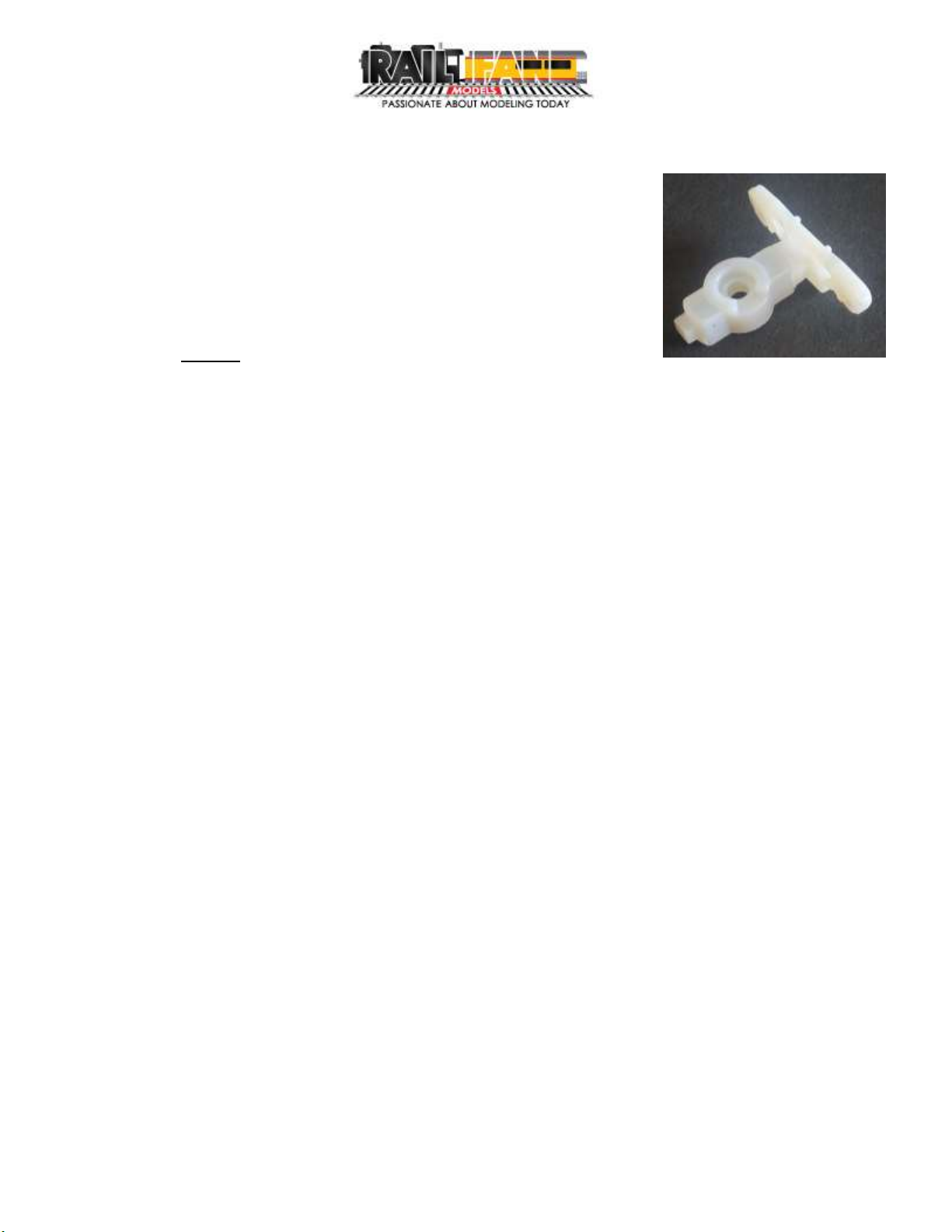
3. Insert Wheelsets into the axle bearing points on the glued
Sideframe. Move the opposite ends into the loose Sideframe.
You will have to wiggle the Sideframe slightly, but try not to
remove it completelt from the Center piece. (The sideframed in
the picture are for demonstration purposes, your parts will be painted.)
4. Hold the Wheelsets in place with one hand. With your free
hand, use a toothpick to pick up a small amount of CA. Apply
the CA inside the gap between the Sideframe and Center.
5. Press the Sideframe against the Center, making sure the
Wheelsets are seated correctly in both Sideframes as the parts
are pressed together.
6. The first Truck is now complete. Repeat for the remaining 5 Trucks.
Assembling Trucks to Span Bolsters
1. At this time set aside the Center Trucks (the ones with oval centers). These get installed at the
very end of the build.
2. Carefully remove the contents of Bag B. There should be 4 screws and 4 springs.
3. Place a screw through bottom of the Truck.
4. Place a spring over the exposed threads of the screw.
5. Align the notch in the top of the Truck to the notch near the end of the Span Boster.
6. Place the screw into the hole near the notch.
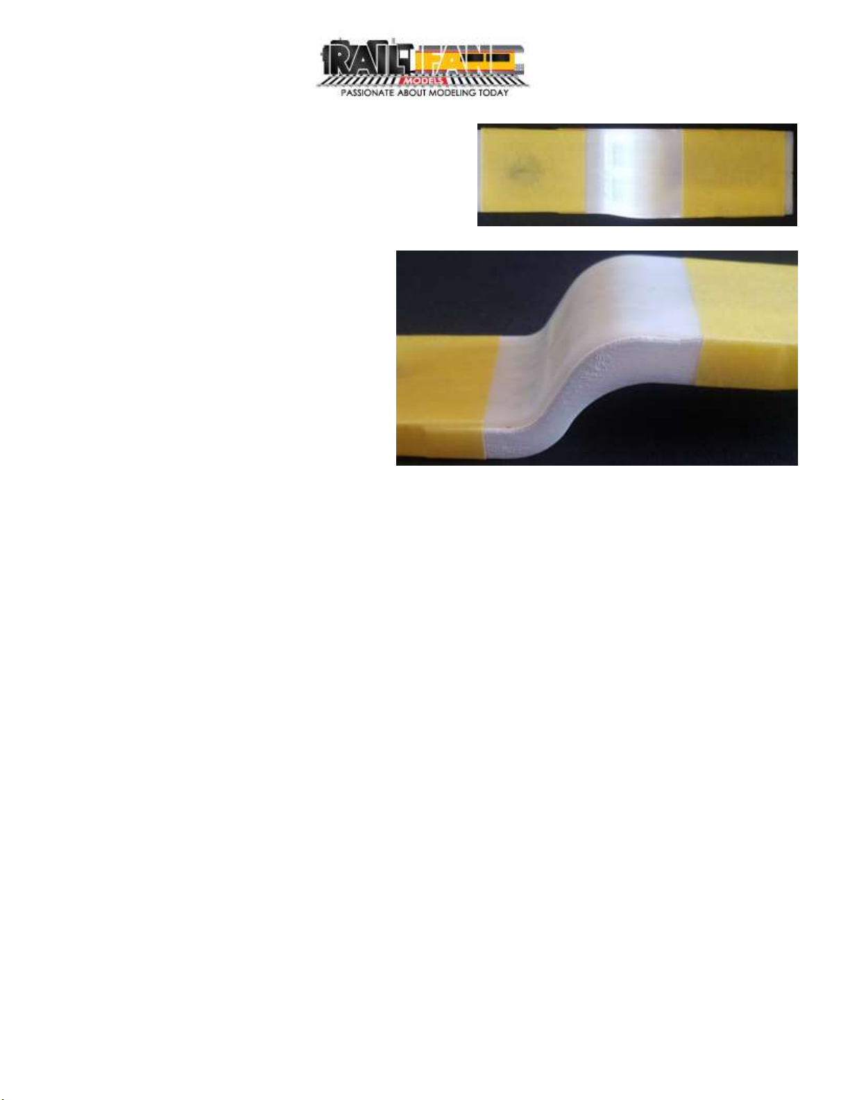
7. Turn the screw counter clockwise (loosening) while applying a little pressure to the screw until
you feel a bump. Turn the screw clockwise (tightening) until the screw bottoms out into the
Span Boster. The holes are pre-threaded, and this process is the easiest way to get the screw
aligned with the threads. When the screw is seated correctly, the Truck will move about 1/16”
between the Span Bolster and screw head. DO NOT OVER TIGHEN THE SCREWS! As shown in
the picture, the springs are pushing the
Trucks up against the screw heads, but
the Trucks will push down against the
Span Bolster leaving a gap between
the screw and Truck center.
8. Repeat for the 3 remaining Trucks.
Page 5of 20
railfanmodels.com
Center Body Pre-Assembly
1. Un-wrap the Center Body. The magnets and weights are installed, halves joined and sanded.
2. Remove the 4 smaller pieces from Bag C.
3. Dry fit the end pieces (flat with a small pipe attached) to the corresponding ends where the
pipe matches the sides.
4. Remove the end pieces, apply CA to the end of the body and re-install the end pieces.
5. Dry fit the remaining 2 End Pivots to the bottom ends of the body. Please note these pieces
are not completely symmetrical. One side is flatter. This side goes toward the center of the
body.
6. Remove the End Pivots, apply CA to the joint area on the body, and re-install the End Pivots.
7. While the seam running lengthwise down the middle of the body has already been sanded,
you may want to finish this to your satisfaction before proceeding. HINT: Spraying a little primer
on the seam will make any imperfections more visible. HINT: If you add any filler or primer, wet
sand with 400 grit sandpaper or finer grit. Do not use anything coarser than 400 grit paper.
Page 6of 20
railfanmodels.com
8. Remove the small parts from Bag D.
There are 4 Shear Plates (thick
rectangles), 4 long Weld Plates, and 8
short Weld Plates.
9. Dry fit the parts into the corresponding
opening on the body. They should fit as
shown. In the case a Weld Plate does
not fit correctly, use a small file to
remove material from the bottom or end
opposite the corner with the hole.
10. Remove these parts from body for
painting.
Paint Center Body
1. Because the body is translucent, we recommend priming it before painting. Any light color
primer will work.
2. Paint the body and brackets gloss red. Using a gloss paint will allow the decals to go on easier
without having to apply a separate clear gloss coat.
3. The brackets should be painted as separate pieces. HINT: The bottom of the sheer plates has
the matte finish and the tops are smooth. Place the sheer plates on double sided tape to hold
in place while painting. HINT: Use small tweezers or needle nose to grab the corner opposite
the holes on the flat pieces. This area will be hidden during final assembly, so does not have to
be 100% covered.
4. We recommend Tru-Color Chinese Red, part number TCP-012, but any dark red color will be
fine, especially if you plan to weather the car. Use the models on our website as reference or
other photos online of these cars.
5. When the red has dried and cured, it is time to
paint the large white areas. To make this easier
for you, there are two masking tools inside Bag D.
Page 7of 20
railfanmodels.com
6. Place the masking tools into the sides opposite
each other. Use the picture as a guide to tape
the masks into place. Use a light adhesion tape
designed for masking paint.
7. The tape on the top deck should be
placed where the taper of the deck
plating meets the thin section of
plating.
8. On the lower deck portion of the
masks, place a pencil mark 3/8 inches
from the end of the mask. The tape
on the bottom deck should be
placed on the marks of the mask.
9. Paint the exposed area gloss white. There is a decal placed in this area so the gloss finish just
helps here.
10. Remove the masking shortly after spraying and is dry to the touch. Don’t let set overnight
though.
11. Mask the other side and paint. Remove the masking as before.
12. Let the paint cure.
Page 8of 20
railfanmodels.com
Center Body Final Assembly
1. Apply CA to the inside of the Sheer Plate cavities on the body.
2. Insert the bottom side of the Sheer Plates into the cavities.
3. Use a toothpick to apply CA to the bottom edge of the Weld Plates and insert into the
appropriate slots on the body. Be sure the tops of the Weld Plates are parallel to the lower
deck body.
End Platform Assembly and Painting
1. Remove the contents of Bag E.
2. Dry fit the Sides and Ends to the Platform Cores. The
top of the Side should be flush with the top of the
Core. The joints should be tight without any gaps. If
a gap does exist, use a small file to remove material
from the side of the Core only.
3. Apply CA to one side of the Core. Use a toothpick to
evenly spread the glue over the entire surface.
4. Press the Side on the Core and hold for 8 seconds.
5. Repeat for the End, then for the opposite Side.
6. Remove one of the Lower Brake Pipes from the
cardboard enclosure.
7. Dry fit the Brake Pipe into the opening on the bottom
of the Core. You will need small needle nose or
tweezers to do this.
8. Remove the Brake Pipe, apply CA to the Core, then
press the Brake Pipe into the core with the same tool.
Page 9of 20
railfanmodels.com
9. Dry fit the Brake Stand to the top of the Platform. The hole for the Brake Wheel should face the
away from the end of the Platform towards the tanks and piping. It should fit into the slots. If
not, use a small file to remove material from the feet of the Brake Stand. Do not glue the
Brake Stand to the Platform yet, as it is easier to add the grab irons and brake wheel before
gluing to the Platform.
10. Repeat Step 2 through 9 for the second Platform End.
11. Carefully remove the Grab Irons and Brake Wheels from Bag F.
12. Test fit the Long Grab Irons on the Platform Sides and Medium Grab Irons on the Ends of the
Platforms. Bend to fit if necessary.
13. Apply CA to the ends of the Grab Irons and insert into the appropriate locations on both
Platforms.
14. Thread the Long Pull Rod through the brackets as shown to where the end just reaches the
bracket on the opposite side.
15. Apply CA to the Rod and bracket
joint and push the Rod in slightly.
16. With needle nose pliers, grab the
bent end of the Short Rod and
apply a small amount to the
straight end. Then insert into the
bracket on the opposite side of the
Long Rod. Hold the Short Rod in
position for 6-8 seconds then
release.
17. Remove the flashing from the back of the Brake Wheels. Test fit the Short Grab Irons, Lever,
and Brake Wheel on both Brake Stands. Bend to fit if necessary.
18. Apply CA to the back of the Grab Irons and Brake wheel and insert on the Brake Stand for
each Platform.
19. Apply CA to the bottoms of the Brake Stands and insert into the slots on the Platforms.
20. We recommend priming the End Platforms before painting.
21. After the primer is dry, airbrush the same color red as the Center Body.
Page 10 of 20
railfanmodels.com
Apply Reflectors and Decals
Use the pictures on the following pages as reference for placement. Note the few subtle differences
with each car number. Both sides of the car are the same, but make sure the A End is used on both
sides of the same End Platform. Same with the B End.
The decals are made by Microscale for Railfan Models, and go on just like any of their other decals.
Cut the decal out with enough extra paper on one side so that it can be held with small needle nose
pliers and not interfere with the decal sliding off. Dip the decal in warm water for 10 seconds and
remove. Let set for 20-30 seconds, then slid the decal off the paper into position with a toothpick.
Blot any excess water with a small piece of paper towel or small dry paint brush. Allow the decals to
dry then brush a “setting”solution over the decals and let dry. A magnifier will come in very handy
viewing, cutting, and placing the decals.
1. It is easier to place the yellow Reflectors from Bag H before placing the decals. We
recommend placing the Platform between 2 small blocks of wood to hold the Platform
vertical. Use two layers of paper towels under the blocks and Platform.
2. Place the reflectors on one side. Use a hobby knife to lift a reflector from the backing and
apply to the car body. Place into position and burnish the reflectors with a toothpick. For
more detailed instructions, go to smokeboxgraphics.com.
3. Remove the Platform, flip it to the other side, replace between the blocks, and place the
reflectors for that side.
4. Repeat for the other platform.
5. Lay the Center Body on its edge. It should lay like this without any support.
6. Apply the reflectors to this side, then flip over and repeat for the other side. Now you are
ready for the decals.
7. Apply the decals from Bag H to the Center Body sides, then top.
8. Apply the decals to the sides and ends of the Platforms.
9. Apply the car number decals to the right side of each Truck side.
10. Apply a clear gloss coat to the sides, ends, and tops of the End Platforms and Center Body to
seal the decals and reflectors.
11. Apply any weathering and/or dull coat at this time.
Page 11 of 20
railfanmodels.com
KRL 300360
Remember that both sides of one End Platform will be “A END”, while the other will be “B END” as
shone above. Also, the 300360 is the only car that uses the large COTS plate that does not have a
white border.
Page 12 of 20
railfanmodels.com
This quadrant in the same on the opposite corner of the car body, not the directly opposite side.
This quadrant of the lower deck is the same on the opposite corner of the deck, not the directly
opposite side.
This quadrant of the lower deck is the same on the opposite corner of the deck, not the directly
opposite side.
This quadrant in the same on the opposite corner of the car body, not the directly opposite side.
Page 13 of 20
railfanmodels.com
KRL 300361
Remember that both sides of one End Platform will be “A END”, while the other will be “B END” as
shone above. Also, the 300360 is the only car that uses the large COTS plate that does not have a
white border.
Page 14 of 20
railfanmodels.com
This quadrant in the same on the opposite corner of the car body, not the directly opposite side.
This quadrant of the lower deck is the same on the opposite corner of the deck, not the directly
opposite side.
This quadrant of the lower deck is the same on the opposite corner of the deck, not the directly
opposite side.
This quadrant in the same on the opposite corner of the car body, not the directly opposite side.
Page 15 of 20
railfanmodels.com
KRL 300362
Remember that both sides of one End Platform will be “A END”, while the other will be “B END” as
shone above. Also, the 300360 is the only car that uses the large COTS plate that does not have a
white border.
Page 16 of 20
railfanmodels.com
This quadrant in the same on the opposite corner of the car body, not the directly opposite side.
This quadrant of the lower deck is the same on the opposite corner of the deck, not the directly
opposite side.
This quadrant of the lower deck is the same on the opposite corner of the deck, not the directly
opposite side.
This quadrant in the same on the opposite corner of the car body, not the directly opposite side.
Page 17 of 20
railfanmodels.com
Final Model Assembly
1. Place the Center Body upside down on a small box.
Be sure there is room between the box and the Weld
Brackets.
2. Place one of the Span Bolsters on the Pivot Point of one end of the Center Body. You will need
to lay something across the bottom of the Center Body and End Truck so the Span Bolster stays
in place.
3. Empty the contents of Bag G.
4. Take a ½ inch screw, push it through the bottom of a Center Truck, put a spring over the
exposed threads, and insert the screw through the center hole of the Span Bolster.
5. Turn the screw counter clockwise (loosening) while applying a little pressure to the screw until
you feel a bump. Turn the screw clockwise (tightening) until the screw bottoms out into the
Span Boster. The holes are pre-threaded, and this process is the easiest way to get the screw
aligned with the threads. When the screw is seated correctly, the Truck will move about 1/16”
between the Span Bolster and screw head. DO NOT OVER TIGHEN THE SCREWS! As shown in
the picture, the springs are pushing the Trucks up against the screw heads, but the Trucks will
push down against the Span Bolster leaving a gap between the screw and Truck center.
6. Repeat for the other end.
7. Now is a good time to test role the car on a track before proceeding. If the car does not track
well or tends to derail, the offending truck(s) may be too tight. Loosen the screw 1/8 turn (45
degrees) and retest. You can repeat again if needed, but make sure the truck movement up
and down does not go past 3/32 inch –doing so will not leave enough screw thread to be
secure. If the spring force is too light (not pushing the truck down to the track if there are
Page 18 of 20
railfanmodels.com
imperfections) you can carefully stretch the spring slightly to increase the spring pressure on
the truck. Do this in very small increments and retest though.
8. Once you are satisfied the car runs on the track properly, you are ready to mount the End
Platforms.
9. With the car right side up, dry fit the End Platforms to the top of the Span Bolsters. The two pins
on the bottom of the End Platform will fit into the holes on the Span Bolster. There will be about
1/16 inch gap between the end platform and the raised edge of the coupler box. The
Platform should be level front to back and side to side.
10. Add CA to the bottom of the center part of the End Platform and place on the Span Bolster
with light pressure for 8 Seconds.
11. Flip the car over once more and place on the box used
previously.
12. Place the ¼ inch screw through the Coupler Cover
and though a Coupler, and insert into the hole in the
coupler box.
13. Turn the screw counter clockwise (loosening) while applying a
little pressure to the screw until you feel a bump. Turn the
screw clockwise (tightening) until the screw head is close to
the Coupler Cover. The holes are pre-threaded, and this
process is the easiest way to get the screw aligned with the
threads. Don’t tighten completely yet.
14. Angle the Coupler Cover to the left slightly as shown in the
picture.
Page 19 of 20
railfanmodels.com
15. Place the Coupler Cut lever as shown on to the bracket of the
Platform End.
16. The Cut Lever should fall through the hole in the bracket of
the Platform. Do not force it through as the bracket might
break.
17. Carefully twist the Cut Lever 180 degrees along the long axis
of the car. The portion of the Cut Lever through the hole will
twist to your right.
18. Move the long part of the Cut Lever to your left.
19. Line up the end of the Cut Lever with the hole on the Coupler
Cover, and move the Coupler Cover to the right so that it is in
line with the Span Bolster.
20. Tighten the Screw just enough that the Coupler Cover will not
move. DO NOT OVER TIGHEN THE SCREW!
Page 20 of 20
railfanmodels.com
21. Repeat Steps 12 through 19 for the other end of the car.
22. Place a little CA on the step and back of the brake manifold.
23. Place the Brake Valve as shown. This
part is pre-painted for your
convenience. Repeat for the other
end of the car.
Congratulations, you have finished! Now go enjoy your car on the track.
Use the box and foam inserts the kit shipped in to store and transport your model. Remove the top
layer of foam and the two foam blocks. Carefully place the model into the rectangle cutout in the
foam. You may need to slightly spread out the foam on the ends of the car while moving it in and
out of the foam. Reverse these steps to take the model back out of the packaging. The foam blocks
should be placed so they do not sit on top of the brake wheels.
If you have a transformer load, you may also store it in the box as well. We recommend placing a
piece of thin paper on top of the center deck of the car, then spread the foam in the center apart
with your fingers while lowering the transformer on the deck. Place the foam blocks up against the
transformer then place the top layer of foam and close the box up. Place the box into the sleeve.

Other Railfan Models Toy manuals

Railfan Models KRL-340320 User manual

Railfan Models

Railfan Models KRL-340320 User manual

Railfan Models TRANSFORMER 3 User manual

Railfan Models

Railfan Models TRANSFORMER 3 User manual

Railfan Models 370350 User manual

Railfan Models

Railfan Models 370350 User manual

Railfan Models TRANSFORMER 2 User manual

Railfan Models

Railfan Models TRANSFORMER 2 User manual

Popular Toy manuals by other brands

Chicco 00010491000000 instruction manual

Chicco

Chicco 00010491000000 instruction manual

Hobbico HCAA0239 Assembly instruction

Hobbico

Hobbico HCAA0239 Assembly instruction

Playskool 51674 Getting started

Playskool

Playskool 51674 Getting started

Hangar 9 PULSE XT 40 ARF Assembly manual

Hangar 9

Hangar 9 PULSE XT 40 ARF Assembly manual

CYmodel BEAVER CY8043B instruction manual

CYmodel

CYmodel BEAVER CY8043B instruction manual

Trix H0 BR 96 manual

Trix

Trix H0 BR 96 manual

Innovative Hobby Supply Porta Potty's BK 6430 General assembly instructions

Innovative Hobby Supply

Innovative Hobby Supply Porta Potty's BK 6430 General assembly instructions

E-FLITE Hurricane 25e TM Assembly manual

E-FLITE

E-FLITE Hurricane 25e TM Assembly manual

Troy Built Models Bonanza V-35 instruction manual

Troy Built Models

Troy Built Models Bonanza V-35 instruction manual

PIKO BR 93 Instructions for use

PIKO

PIKO BR 93 Instructions for use

Kettler Kettcar KABRIO Assembly instructions

Kettler

Kettler Kettcar KABRIO Assembly instructions

Eduard King Tiger Porsche turret quick start guide

Eduard

Eduard King Tiger Porsche turret quick start guide

REVELL ’66 CHEVY IMPALA SS 396 2’N1 manual

REVELL

REVELL ’66 CHEVY IMPALA SS 396 2’N1 manual

George Home Wooden pirate ship Assembly guide

George Home

George Home Wooden pirate ship Assembly guide

Black Horse Model BH149 Instruction manual book

Black Horse Model

Black Horse Model BH149 Instruction manual book

M.T.H. Premier GP40 Diesel Engine Operator's manual

M.T.H.

M.T.H. Premier GP40 Diesel Engine Operator's manual

ROBBE Bucker Jungmeister 3041 Assembly and operating instructions

ROBBE

ROBBE Bucker Jungmeister 3041 Assembly and operating instructions

marklin 29210 user manual

marklin

marklin 29210 user manual

manuals.online logo
manuals.online logoBrands
  • About & Mission
  • Contact us
  • Privacy Policy
  • Terms and Conditions

Copyright 2025 Manuals.Online. All Rights Reserved.