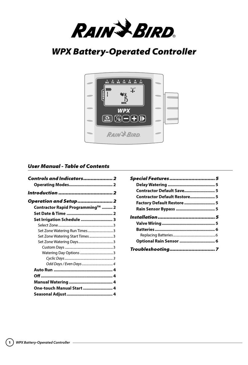
Rain Bird WPX User manual
Other Rain Bird Controllers manuals
Rain Bird
Rain Bird ESP-TM2 User manual
Rain Bird
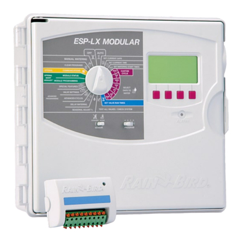
Rain Bird ESP-LX User manual
Rain Bird
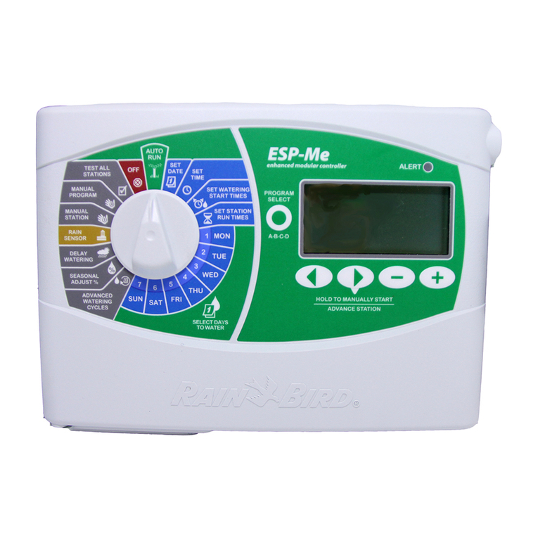
Rain Bird ESP-Me User manual
Rain Bird
Rain Bird RAIN CLOCK PC-104 User manual
Rain Bird
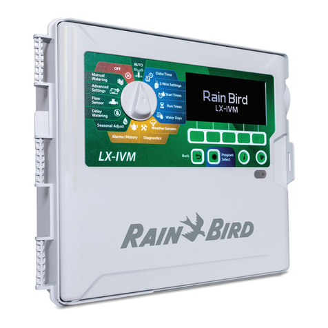
Rain Bird ESP-LXIVM Series Installation guide
Rain Bird
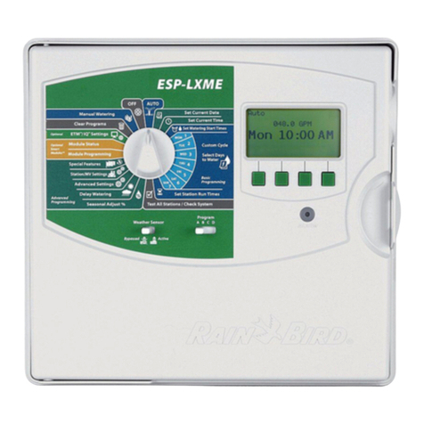
Rain Bird ESP-LXME User manual

Rain Bird
Rain Bird ESP-TM2 User manual
Rain Bird
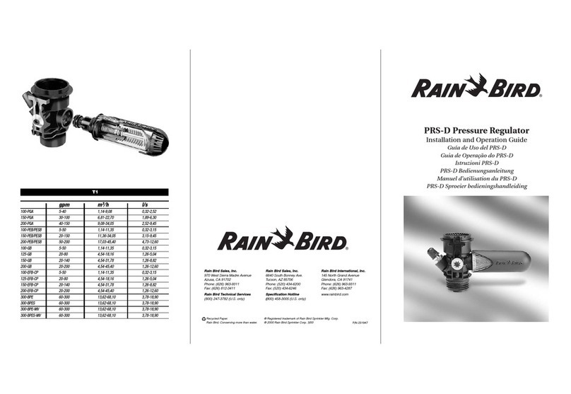
Rain Bird PRS-D Operating instructions
Rain Bird
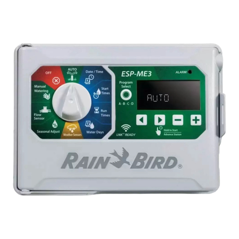
Rain Bird ESP-ME3 User manual
Rain Bird
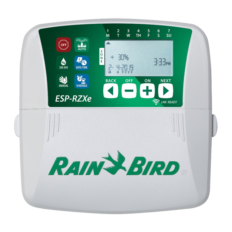
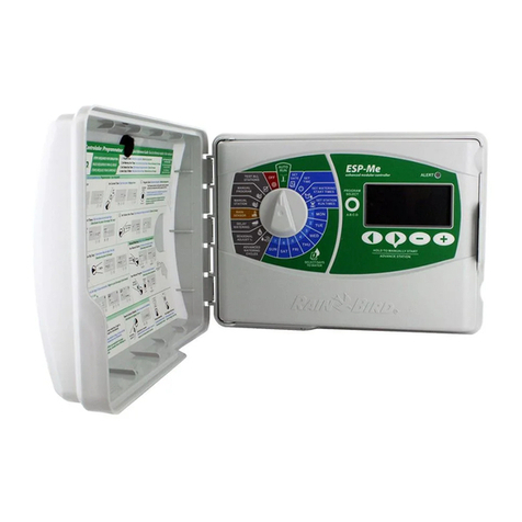
Rain Bird ESP-RZXe User manual
Rain Bird
Rain Bird ESP-Me Series User manual
Rain Bird
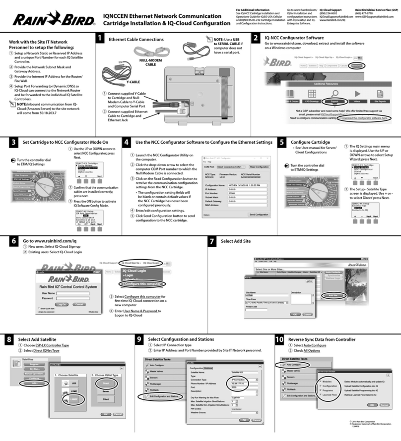
Rain Bird IQNCCEN User manual
Rain Bird
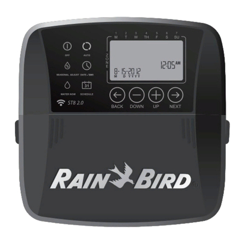
Rain Bird ST8I-INTL Instruction Manual
Rain Bird
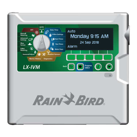
Rain Bird ESP-LXIVM User manual
Rain Bird
Rain Bird ET Manager Series User manual
Rain Bird
Rain Bird E-6C Instruction manual
Rain Bird
Rain Bird Image Series User manual
Rain Bird
Rain Bird ESP-MC User manual

Rain Bird
Rain Bird ESP-LX Assembly instructions

Rain Bird
Rain Bird ESP-LXIVM Series Instruction sheet
Popular Controllers manuals by other brands

Digiplex
Digiplex DGP-848 Programming guide

YASKAWA
YASKAWA SGM series user manual

Sinope
Sinope Calypso RM3500ZB installation guide

Isimet
Isimet DLA Series Style 2 Installation, Operations, Start-up and Maintenance Instructions

LSIS
LSIS sv-ip5a user manual

Airflow
Airflow Uno hab Installation and operating instructions
