Troubleshooting
Decoders
General Information
Calculate expected “At Rest” current
draw on each wire path and each
LDI or SDI interface.
• FD-101 = 0.5 mA
• FD-102 = 0.5 mA
• FD-202 = 1.0 mA
• FD-401 = 1.0 mA
• FD-601 = 1.0 mA
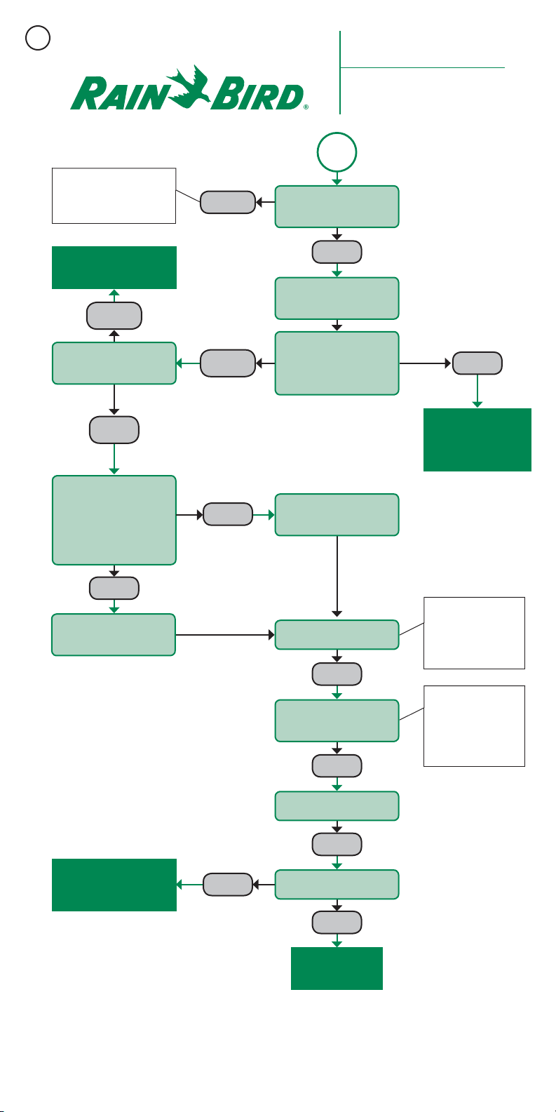
Prior to troubleshooting when using
a clamp meter, make sure you know
the static current draw of the wire
path or sections of wire path you will
be troubleshooting. (1) To calculate
the static current draw at an individual
wire path section, add the number of
decoders that are downstream from the
test point, and multiply it by the current
draw of each decoder to determine
the total calculated current draw of
the wire section after the test point. (2)
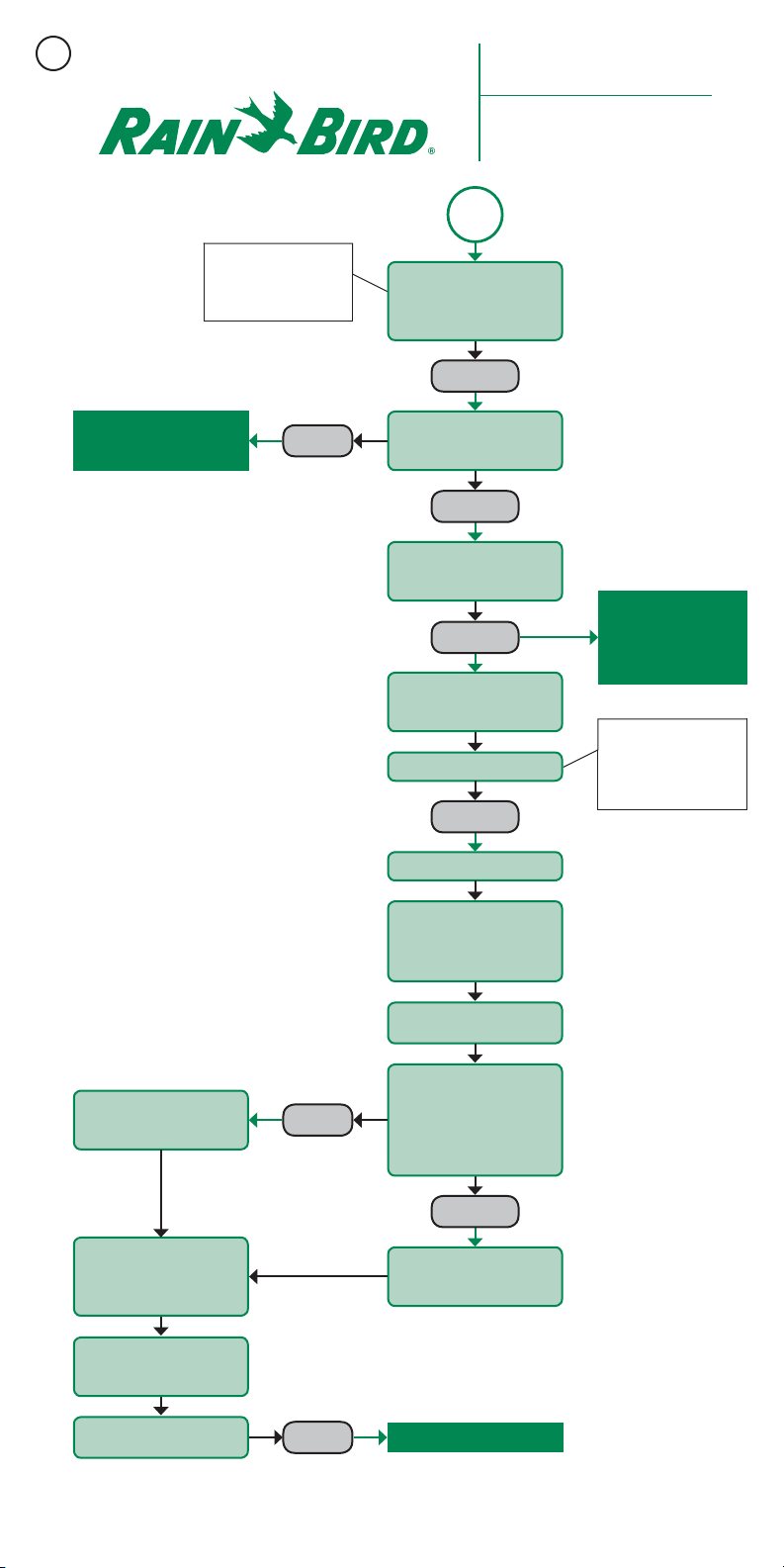
To calculate the static current draw of
an entire wire path, add the number
of decoders on the entire wire path,
and multiply it by the current draw of
each decoder to determine the total
calculated current draw of the wire path.
(3) To calculate the static current draw of
an entire interface, add up all calculated
wire path current draws that are
connected to the interface.
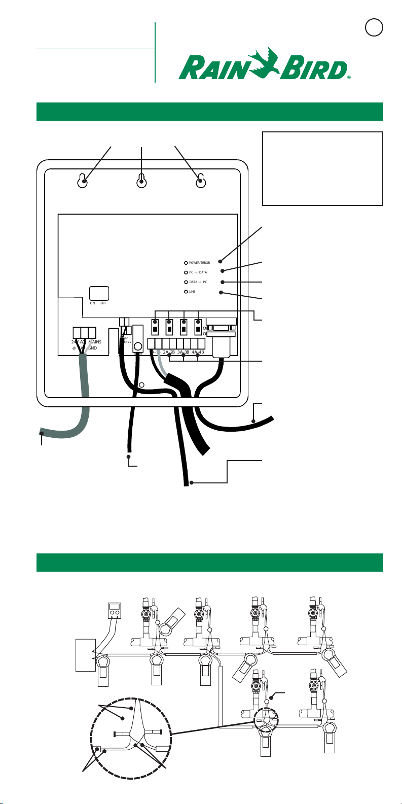
NOTE: If the wire path has been looped,
you must break the loop in order to
properly troubleshoot current draw
using a clampmeter.
(see Locating A Bad Decoder on page 4).
Example:
BLUE WIRE
• 100 FD-101 x 0.5 mA = 50 mA
• 25 FD-202 x 1.0 mA = 25 mA
• 10 FD-401 and FD-601 = 10 mA
• Total Blue Wire current = 85 mA
RED WIRE
• 80 FD-102 x 0.5 mA = 40 mA
• 20 FD-202 x 1.0 mA = 20 mA
• 15 FD-401 and FD-601 = 15 mA
• Total Red Wire current = 75 mA
• Total Current for LDI or SDI = 85 +
75 = 160 mA
Tool List
• Spare Decoders
• Clamp Meter (current specifications are
available by calling 1-866-GSP-XPRT)
• Digital Multi-Meter
• Direct Bury Wire Splice Kits
• Maxi Wire Strippers
• Wire Strippers
• Linesman Pliers
• Extra Maxi Wire
• Updated “As-Built” drawing (“As Built”
should show wire path colors, decoder locations,
expected current draw per wire path and expected
current draw per LDI/SDI.)
2