Ediseja 21 CMU 100 Series User manual
CMU 100 / 2.9.6.6.6.6.6.6.6 – 12, CMU 100 / 8.9.6.6.6.6.6.6.6 – 12,
CMU 100 / 2.9.6.6.6.6.6.6 – 12, CMU 100 / 8.9.6.6.6.6.6.6 – 12,
CMU 100 / 2.9.6.6.6.6.6 – 12, CMU 100 / 8.9.6.6.6.6.6 – 12,
CMU 100 / 2.9.6.6.6.6 – 12, CMU 100 / 8.9.6.6.6.6 – 12
Company: Device: Document: Code: Version: Date:
Ediseja 21 CMU 100 / 2.9.6.6.6.6.6.6.6 – 12 User manual CMUMU296 V3 15.11.2016
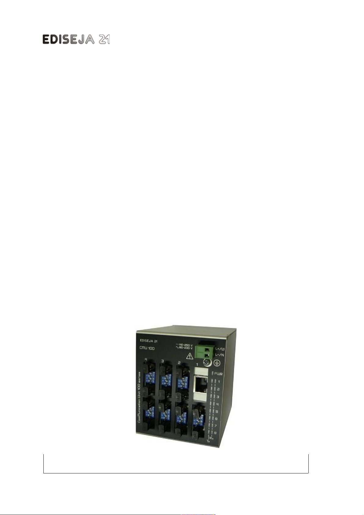
CMU 100
10/100Base-Tx
Ethernet to 7x, 6x, 5x,
4x Mu timode Fiber
Optic Star Coup er
User Manua

CMU 100 - 10/100Base-Tx E herne o 7x, 6x, 5x, 4x
Content
1 PREFACE.......................................................................................................3
2 CMU 100 SYSTEM.........................................................................................5
2.1 DESCRIPTION..................................................................................................................... 5
2.1.1 SOFTWARE...................................................................................................................... 5
2.1.2 HARDWARE...................................................................................................................... 5
3 10/100BASE-TX ETHERNET TO x MULTIMODE FIBER OPTIC STAR
COUPLER.............................................................................................................
3.1 DESCRIPTION.....................................................................................................................
3.2 TYPICAL APPLICATIONS...................................................................................................
3.3 APPEARANCE..................................................................................................................... 9
3.4 HARDWARE DESCRIPTION...............................................................................................9
3.4.1 MAIN BOARD.................................................................................................................... 9
3.4.2 ETHERNET INTERFACE BOARD...................................................................................10
3.4.2.1 LANTRONIX CPR MANAGER......................................................................................11
3.4.2.2 LANTRONIX INSTALLER SETTINGS..........................................................................12
3.4.3 MULTIMODE FIBER OPTIC INTERFACE BOARD.........................................................17
4 SCHEMATIC.................................................................................................19
5 INSTALLATION............................................................................................20
5.1 INSTALLATION.................................................................................................................. 20
6 COMMISSIONING & MAINTENACE..........................................................22
6.1 COMMISSIONING.............................................................................................................. 22
6.2 MAINTENANCE................................................................................................................. 22
TECHNICAL DATA......................................................................................23
8 DIMENSIONS...............................................................................................25
9 ORDERING...................................................................................................26
Page: Company: Device: Document: Code: Version: Date:
2 Ediseja 21 CMU 100 / 2.9.6.6.6.6.6.6.6 – 12 User manual CMUMU296 V3 15.11.2016

PREFACE
1 PREFACE
Liability statement
We have checked he con en s of his manual o ensure ha he descrip ions of bo h hardware
and sof ware are as accura e as possible. However, devia ions may occur so ha no liabili y can
be accep ed for any errors or omissions con ained in he informa ion given.
The con en s of his manual will be checked in periodical in ervals, correc ions will be made in
he following edi ions.
We reserve he righ o make echnical improvemen s wi hou no ice.
Contact
If you have any ques ions or commen s rela ed o his produc please con ac us on:
Ediseja 21 d.o.o.
Drenov Gric 175
1360 Vrhnika
Slovenia – EU
Tel: 00 386 51 643 411, 051 643 411
Email: grega.flander@ediseja21.com
www.ediseja21.com
Copyright
Copyrigh © Ediseja 21, 2016. All righ s reserved.
Explanation of the symbols
Read he ins ruc ions!
Device was es ed wi h 2,5 kV AC vol age o check he device insula ion.
Device ground erminal.
Was e Elec rical and Elec ronic Equipmen (WEEE) Direc ive 2002/96/EC; he affixed
produc label indica es ha you mus no discard his elec rical/elec ronic produc in
domes ic household was e.
Warnings
In his paper he following erms are used:
Danger
indica es ha dea h, severe personal injury or subs an ial proper y damage will resul if proper
precau ions are no aken.
Company: Device: Document: Code: Version: Date: Page:
Ediseja 21 CMU 100 / 2.9.6.6.6.6.6.6.6 – 12 User manual CMUMU296 V3 15.11.2016 3
CMU 100 - 10/100Base-Tx E herne o 7x, 6x, 5x, 4x
Warning
indica es ha dea h, severe personal injury or subs an ial proper y damage can resul if proper
precau ions are no aken.
Cau ion
indica es ha minor personal injury or proper y damage can resul if proper precau ions are no
aken. This par icularly applies o damage on or in he device i self.
General information
These paper con ain he informa ion ha is necessary for he proper and safe opera ion of he
described devices. This paper is in ended for echnically qualified personnel.
Warning!
Hazardous voltage is present inside the device during operation. Disregarding of safety
rules can result in severe personal injury or property damage.
Only qualified personnel may work with described devices after being familiar with warnings and
safety notices in this paper and other safety regulations.
Warning!
Device must operate completely assembled! Device must be used as described. No
modifications of the device should be made.
Warning!
Do not open device while it is energized! Hazardous voltage is present inside the
device. Disconnect all connectors before opening!
Warning!
If device is damaged disconnect it from power supply! Send it to the manufacturer for
inspection.
Warning!
Connect to earth before attaching power supply!
Page: Company: Device: Document: Code: Version: Date:
4 Ediseja 21 CMU 100 / 2.9.6.6.6.6.6.6.6 – 12 User manual CMUMU296 V3 15.11.2016

CMU 100 SYSTEM
2 CMU 100 SYSTEM
2.1 DESCRIPTION
Communica ion uni (CMU 100) is modular sys em of communica ion devices ha can be used
for various of asks such as:
communica ion conver er (for example RS232 o RS485)
s ar coupler (for example 1 fiber op ic o 7 fiber op ics)
repea er (for example RS485/485)
communica ion isola or (for example for preven ing ground loops)
communica ion lis ener - debugger
PC serial com por ex ender (for example USB o 4 serial com)
CMU 100 device is a couple of sof ware and hardware. For differen purposes, differen sof ware
versions and differen hardware configura ion have been developed.
2.1.1 SOFTWARE
Sof ware is applica ion dependen and allows differen hardware configura ions. Sof ware's ask
is swi ching be ween communica ion por s and allows almos any combina ion be ween hem.
2.1.2 HARDWARE
Hardware is based on main board wi h power supply and por swi ching logic. On ha board,
in erface boards are a ached. CMU 100 can handle up o 8 differen in erface boards. Curren ly
available in erface boards:
RS232
isola ed RS485
Mul imode Fiber Op ic wi h ST and SMA connec ors
Singlemode Fiber Op ic wi h SC connec ors
USB
e herne (wi h one vir ual com por )
Housing is aluminium and in ended for moun on s andard DIN 35 rail (acc. o DIN EN 50022). 3
differen housings have been made. Depends on how many in erfaces device has, appropria e
housing is used.
Hardware settings
All se ings on he device can be made from ou side by a DIL swi ch. I is no necessary o open
he housing.
Company: Device: Document: Code: Version: Date: Page:
Ediseja 21 CMU 100 / 2.9.6.6.6.6.6.6.6 – 12 User manual CMUMU296 V3 15.11.2016 5

CMU 100 - 10/100Base-Tx E herne o 7x, 6x, 5x, 4x
Due to similarity among stated types, only type with optic port will be described.
Page: Company: Device: Document: Code: Version: Date:
6 Ediseja 21 CMU 100 / 2.9.6.6.6.6.6.6.6 – 12 User manual CMUMU296 V3 15.11.2016
Picture 1: CMU 100 system general diagram

10/100BASE-TX ETHERNET TO 7x MULTIMODE FIBER OPTIC STAR COUPLER
3 10/100BASE-TX ETHERNET TO x MULTIMODE
FIBER OPTIC STAR COUPLER
3.1 DESCRIPTION
S ar coupler is communica ion device ha ransfer da a from one (mas er) o more han one
(slave) por . Example is when we need access o one device wi h several PCs. I can also be
used when communica ion from PC o mul iple devices is needed.
This device con ains one E herne in erface (mas er) and seven 820 nm wave lengh mul imode
fiber op ic (slaves). Da a is send from mas er por o all slave por s. On he o her hand, da a
from ei her slave por is send o mas er por only.
Wide power supply vol age allows connec ion o all common s a ion ba eries. Addi ionaly i can
be also connec ed o s andard AC vol ages.
This device is in ended for use in cubicles and cabine s in all kinds of power produc ion,
ransmission and dis ribu ion s a ions. I requires no main enace. All normaly used connec ors,
swi ches and ligh indica ors are accessed a he fron side of he device. One ligh indica or
indica es power supply vol age, o hers indica e communica ion ransfer.
Fiber op ic communica ion allows longer dis ances be ween devices wi hou elec romagne ic
dis urbances. Fiber op ic logic can be se o posi ive or nega ive logic for ransmi er and receiver
separa edly. They can be se by DIP swi ch a he fron side of he communica ion in erface.
3.2 TYPICAL APPLICATIONS
Typical applica ion is communica ion wi h PC wi h SCADA applica ion, in con rol room and
pro ec ion relays, power me ers, e c wi h FO mm, in swi chgear, wi hou elec romagne ic
dis urbances.
Company: Device: Document: Code: Version: Date: Page:
Ediseja 21 CMU 100 / 2.9.6.6.6.6.6.6.6 – 12 User manual CMUMU296 V3 15.11.2016 7


APPEARANCE
3.3 APPEARANCE
3.4 HARDWARE DESCRIPTION
This configura ion of device is made from main board (power supply, LEDs, swi ches and logic
swi ch), one E herne in erface board and seven mul imode fiber op ic boards.
3.4.1 MAIN BOARD
Power LED indica es ha device is urned on. The righ LEDs of one por shows ac ivi y on
receive (Rx) line and he lef one shows ac ivi y on ransmi (Tx) line.
On he bo om side of device are swi ches and JTAG connec or which is in ended for
downloading necessary sof ware. Do no connec any hing o ha connec or.
Addi ional swi ches allows echo on each por . Echo can be se on or off for each por .
Switches
Switch 1 2 3 4
Description Echo por 1 Echo por 2 Echo por 3 Echo por 4
Position OFF Echo off Echo off Echo off Echo off
Position ON Echo on Echo on Echo on Echo on
Default position OFF OFF OFF OFF
Switch 5 6 8
Description Echo por 5 Echo por 6 Echo por 7 Echo por 8
Position OFF Echo off Echo off Echo off Echo off
Company: Device: Document: Code: Version: Date: Page:
Ediseja 21 CMU 100 / 2.9.6.6.6.6.6.6.6 – 12 User manual CMUMU296 V3 15.11.2016 9
Picture 3: Front vie (left) & bottom vie (right)
CMU 100 - 10/100Base-Tx E herne o 7x, 6x, 5x, 4x
Switch 5 6 8
Position ON Echo on Echo on Echo on Echo on
Default position OFF OFF OFF OFF
Configuration of ports
Port 1 2 3 4 5 6 8
Interface E herne FO MM FO MM FO MM FO MM FO MM FO MM FO MM
3.4.2 ETHERNET INTERFACE BOARD
Description
10/100Base-TX e herne por wi h one serial com por server and RJ45 connec or. I enables
communica ion on serial por wi h 300 bi /s o 921,6 kbi /s. Addi ional programs can crea e
vir ual com por on compu er, which is connec ed o he CMU IP number. This in erface also
enables connec ion be ween wo CMU devices via e herne .
LED description
Upper LED - Link Lower LED - Activity
State Meaning State Meaning
Off No Link Off No Ac ivi y
Amber 10 Mbi /s Amber Half Duplex
Green 100 Mbi /s Green Full Duplex
RJ45 Ethernet Port Pin Configuration
Signal Direction Contact Function
TX+ Ou 1 Differen ial E herne ransmi da a +
TX- Ou 2 Differen ial E herne ransmi da a -
RX+ In 3 Differen ial E herne receive da a +
No used 4 Termina ed
No used 5 Termina ed
RX- In 6 Differen ial E herne receive da a -
No used 7 Termina ed
No used 8 Termina ed
Chassis
ground Case
Page: Company: Device: Document: Code: Version: Date:
10 Ediseja 21 CMU 100 / 2.9.6.6.6.6.6.6.6 – 12 User manual CMUMU296 V3 15.11.2016

HARDWARE DESCRIPTION
Cable
If device is connec ed o he swi ch, TIA/EIA 568A or TIA/EIA 568B cable should be used. If
device is connec ed o he PC wi hou cable de ec ion op ion, TIA/EIA 568A CROSSOVER or
TIA/EIA 568B CROSSOVER should be used.
Software setting
For using his in erface wo programs are needed: CPR Manager and Ins aller. Bo h can be
ob ained from www.ediseja21.com\cmu100-2por s.h m or www.lan ronix.com. CPR Manager is
needed for se ing and redirec ing E herne por o he vir ual com por on PC. Ins aller is needed
for se ing serial com por speed, pari y, flow con rol,...
3.4.2.1 LANTRONIX CPR MANAGER
Company: Device: Document: Code: Version: Date: Page:
Ediseja 21 CMU 100 / 2.9.6.6.6.6.6.6.6 – 12 User manual CMUMU296 V3 15.11.2016 11
Picture 4: RJ45 connector
Picture 5: Cable

CMU 100 - 10/100Base-Tx E herne o 7x, 6x, 5x, 4x
Se CMU IP number and TCP Por o 10001 o Com por ha is needed.
NOTE! Press „Save“ to save settings!
3.4.2.2 LANTRONIX INSTALLER SETTINGS
Page: Company: Device: Document: Code: Version: Date:
12 Ediseja 21 CMU 100 / 2.9.6.6.6.6.6.6.6 – 12 User manual CMUMU296 V3 15.11.2016
Picture 6: CPR Manager program

CMU 100 - 10/100Base-Tx E herne o 7x, 6x, 5x, 4x
Page: Company: Device: Document: Code: Version: Date:
14 Ediseja 21 CMU 100 / 2.9.6.6.6.6.6.6.6 – 12 User manual CMUMU296 V3 15.11.2016
Picture 11: Set as sho n.
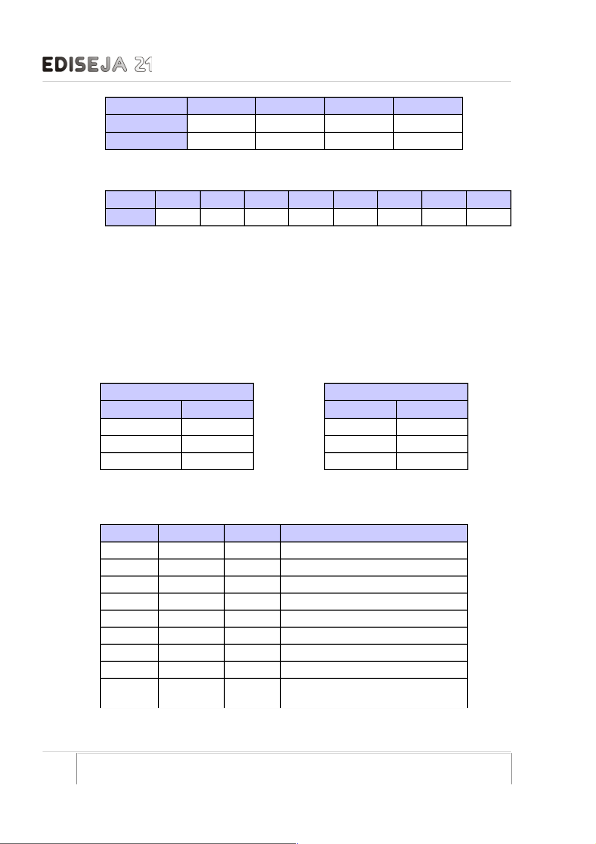
Picture 10: Use „IP Configuration/Use the follo ing IP configuration:“ settings and set IP according to your
needs.

CMU 100 - 10/100Base-Tx E herne o 7x, 6x, 5x, 4x
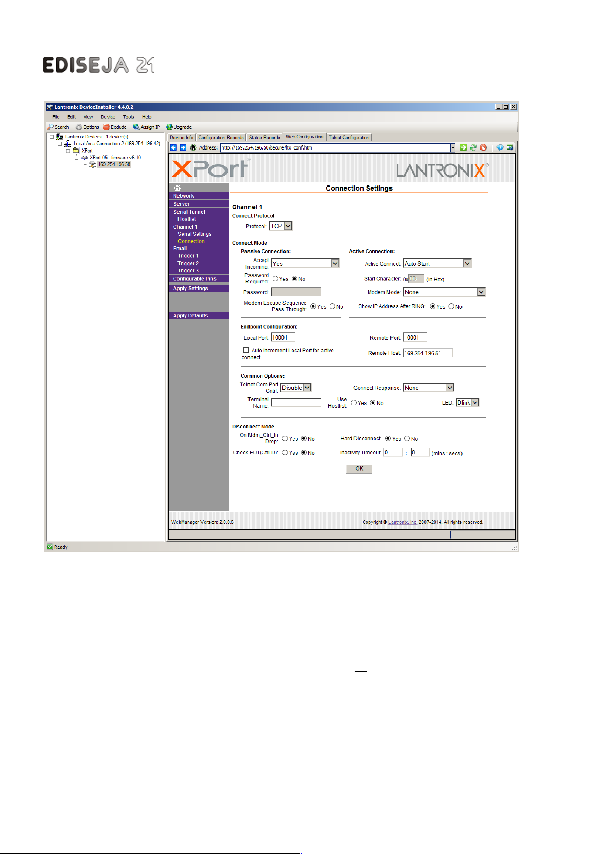
„Endpoin Configura ion/Local Por “ se ings mus be se a 10001!
If wo CMU devices need o be connec ed via e herne por , se following also:
„Connec Mode / Ac ive Connec ion / Ac ive Connec o Au o S ar
„Endpoin Configura ion / Remo e Por “ o 10001
„Endpoin Configura ion / Remo e Hos “ o o her CMU IP.
Page: Company: Device: Document: Code: Version: Date:
16 Ediseja 21 CMU 100 / 2.9.6.6.6.6.6.6.6 – 12 User manual CMUMU296 V3 15.11.2016
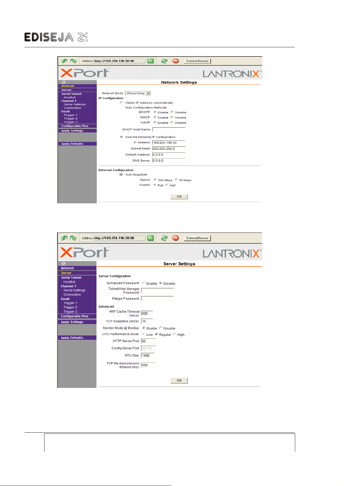
Picture 13: Connection settings
HARDWARE DESCRIPTION
NOTE! Always press "OK" when settings is changed. Press „Apply Settings“ to save settings into
device! Wait for device to reset.
NOTE! While device is resetting, it is recommended that web browser is restarted. Otherwise old
settings may be displayed in web browser after device restarts.
3.4.3 MULTIMODE FIBER OPTIC INTERFACE BOARD
Description
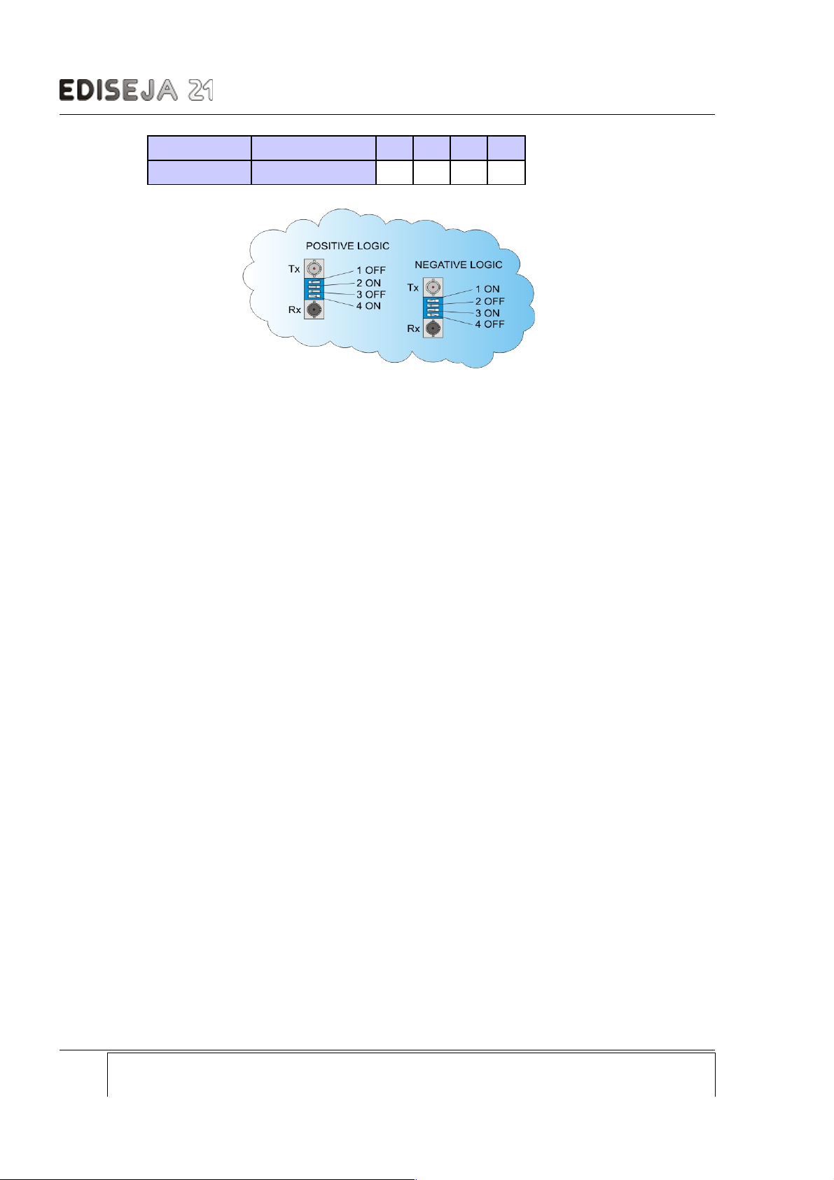
Single, full duplex, mul imode, fiber op ic por wi h ST connec ors wi h posi ive or nega ive logic.
Hardware settings
For proper func ioning of ha board, op ic logic mus be se :
Fiber optic logic settings
Switch SW1 Light in idle state 1 2 3 4
Positive logic OFF OFF ON OFF ON
Company: Device: Document: Code: Version: Date: Page:
Ediseja 21 CMU 100 / 2.9.6.6.6.6.6.6.6 – 12 User manual CMUMU296 V3 15.11.2016 17
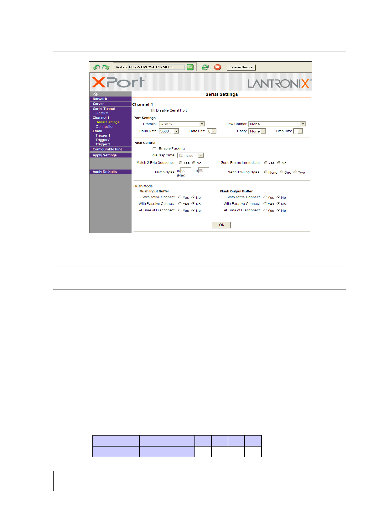
Picture 14: „Port settings/Protocol“ settings must be set at RS232! Set other port settings according to
your needs.
CMU 100 - 10/100Base-Tx E herne o 7x, 6x, 5x, 4x
Switch SW1 Light in idle state 1 2 3 4
Negative logic ON ON OFF ON OFF
Page: Company: Device: Document: Code: Version: Date:
18 Ediseja 21 CMU 100 / 2.9.6.6.6.6.6.6.6 – 12 User manual CMUMU296 V3 15.11.2016
Picture 15: Multimode fiber optic interface board appearance

SCHEMATIC
4 SCHEMATIC
Company: Device: Document: Code: Version: Date: Page:
Ediseja 21 CMU 100 / 2.9.6.6.6.6.6.6.6 – 12 User manual CMUMU296 V3 15.11.2016 19
Picture 16: Left: CMU 100 / 2.9.6.6.6.6.6.6.6 – 12 & CMU 100 / 8.9.6.6.6.6.6.6.6 – 12
Right: CMU 100 / 2.9.6.6.6.6 – 12 & CMU 100 / 8.9.6.6.6.6 – 12 general diagram

CMU 100 - 10/100Base-Tx E herne o 7x, 6x, 5x, 4x
5 INSTALLATION
5.1 INSTALLATION
Warning!
Hazardous voltage is present inside the device during operation. Disregarding of safety
rules can result in severe personal injury or property damage.
Only qualified personnel may work with described devices after being familiar with warnings and
safety notices in this paper and other safety regulations.
Following instruction must be taken into consideration:
The device mus be accessible o qualified personnel only.
The device is permi ed o opera e in enclosed housing or cabine only.
The device loca ion mus be vibra ion-free.
The admisible opera ing empera ure mus be observed.
Check he device for damage a unpacking. If device is damaged i mus no be ins alled
bu i should be send o he manufac urer for repair.
The device should no be opened.
The device should be moun ed on a 35 mm rail (acc o EN 50022).
A ach ground wire before a aching power supply. Device mus be grounded during
opera ion!
Single core or s randed wire 0,5 – 2,5 mm2 mus be used for power supply connec ion. If
s randed wire is used, ferrules mus be used o preven fraying. Recommended s ripping
lengh is 5 mm.
Pro ec ive ear hing wire mus be ermina ed wi h inned copper ear erminal.
The prescribed bending radius of he op ical fibre cables mus be observed.
Page: Company: Device: Document: Code: Version: Date:
20 Ediseja 21 CMU 100 / 2.9.6.6.6.6.6.6.6 – 12 User manual CMUMU296 V3 15.11.2016
Other manuals for CMU 100 Series
4
This manual suits for next models
8
Table of contents
Other Ediseja 21 Media Converter manuals


Popular Media Converter manuals by other brands


Siko
Siko WV5800M Translation of the original installation instructions

Contemporary Research
Contemporary Research QIP-D product manual

LEGRAND
LEGRAND Raritan D4CBL-ADUPS2 Quick setup guide

Monoprice
Monoprice Blackbird21875 user manual

ADF Web
ADF Web HD67423 user manual

NeoCharge
NeoCharge Smart Splitter user manual