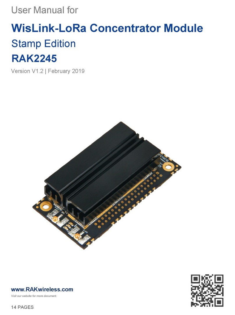
RAKwireless WisLink LPWAN RAK5146 User manual

WisLink LPWAN RAK5146 User Manual
PRODUCT NAME: WisLink LPWAN Concentrator
MODEL NAME: RAK5146
1 Product description
RAK5146 is a WisLink LPWAN Concentrator Module with mini-PCIe form factor based on Semtech SX1303 and
SX1262 for Listen Before Talk feature, which enables easy integration into an existing router or other network
equipment to give it LPWAN Gateway capabilities. It can be used in any embedded platform offering a free mini-
PCIe slot with SPI/USB connection. Furthermore, ZOE- M8Q GPS chip is integrated onboard.
This module is an exceptional, complete, and cost-efficient gateway solution offering up to 10 programmable
parallel demodulation paths, 8 x 8 channel LoRa packet detectors, 8 x SF5-SF12 LoRa demodulators, and 8 x SF5-
SF10 LoRa demodulators. It is capable of detecting an uninterrupted combination of packets at 8 different spreading
factors and 10 channels with continuous demodulation of up to 16 packets. This product is best for smart metering
fixed networks and Internet-of-Things (IoT) applications.
Manufacturer’s address:
Shenzhen RAKwireless Technology Co., Ltd.
Room 506, Bldg B, New Compark, Pingshan First Road, Taoyuan Street, XiLi Town Nanshan District, Shenzhen, China
Instructions for use and safety information:
For safe commissioning, please read this manual and the documentation of your product. The complete
documentation and further information about your product can be found in the RAKwireless
Documentation Center: https://docs.rakwireless.com/Product-Categories/WisLink. To do this, enter
the product name or item number in the search box and click Search.

2 Product specifications
Feature
Specifications
Form factor
Mini PCI express
Baseband processor Semtech SX1302
emulates 8x 8 channel LoRa packet detectors
8x SF5-SF12 LoRa demodulators, 8x SF5-SF10 LoRa demodulators
Rx sensitivity down to -139dBm@SF12, BW 125 kHz.
LoRa feature
Supports global license-free frequency band (EU868, CN470, US915, AS923, AU915,
KR920, IN865)*
Listen Before Talk (optional)
Fine Time Stamp (optional)
Frequency**
EU433/CN470/EU868/US915/AS923/AU915/IN865/KR920
Power supply
3.3v
Compatibility
RJ45 (10/100 Mbps)
LoRa:
GPS:
Antenna
*Supported bands depends of the model.
3 Interfaces

RAK5146 Interfaces are listed below:
Power Supply - The RAK5146 concentrator module must be supplied through the 3.3Vaux pins by a DC
power supply. The voltage needs to be stable since the current drawn can vary significantly during operation
based on the power consumption profile of the SX1303 chip (for more information, see the SX1303
Datasheet (opens new window)).
SPI Interface - SPI interface mainly provides for the Host_SCK, Host_MISO, Host_MOSI, Host_CSN pins of the
system connector. The SPI interface gives access to the configuration register of SX1303 via a synchronous
full-duplex protocol. Only the slave side is implemented.
USB Interface - The USB interface mainly provides for the USB_D+, USB_D- pins of the system connector.
The USB interface gives access to the configuration register of SX1303 via an MCU STM32L412KBU6. Only
the slave side is implemented.
UART and I2C Interface - RAK5146 integrates a ZOE-M8Q GPS module which has UART and I2C interface.
The PINs on the golden finger provide a UART connection and an I2C connection, which allows direct access
to the GPS module. The PPS signal is not only connected to SX1303 internally but also connected to the
golden finger which can be used by the host board.
GPS_PPS - RAK5146 includes the GPS_PPS input for received packets time-stamped and Fine timestamp.
RESET - RAK5146 SPI card includes the RESET active-high input signal to reset the radio operations as
specified by the SX1303 Specification. RAK5146 USB card’s RESET is controlled by MCU.
Antenna RF Interface - The module have one RF interface over a standard UFL connector (Hirose U. FL-R-
SMT) with a characteristic impedance of 50Ω. The RF port (J1) supports both Tx and Rx, providing the
antenna interface
Notes:
Do not power the module without connected antenna/s. This may damage the radios.

4 Electrical requirements
ELECTRICAL REQUIREMENTS
Stressing the device above one or more of the ratings listed in the Absolute Maximum Rating section may cause
permanent damage. These are stress ratings only. Operating the module at these or any conditions other than those
specified in the Operating Conditions sections of the specification should be avoided. Exposure to Absolute
Maximum Rating conditions for extended periods may affect device reliability.
The operating condition range defines those limits within which the functionality of the device is guaranteed. Where
application information is given, it is advisory only and does not form part of the specification.
ABSOLUTE MAXIMUM RATING
The limiting values given below are following the Absolute Maximum Rating System (IEC 134).
Symbol
Description
Condition
Min
Max
3.3Vaux
Module supply voltage
Input DC voltage at 3.3Vaux pins
-0.3 V
3.6 V
USB
USB D+/D- pins
Input DC voltage at USB interface pins
3.6 V
RESET
RAK5146 reset input
Input DC voltage at RESET input pin
-0.3 V
3.6 V
SPI
SPI interface
Input DC voltage at SPI interface pin
-0.3 V
3.6 V
GPS_PPS
GPS 1 PPS input
Input DC voltage at GPS_PPS input pin
-0.3 V
3.6 V
Rho_ANT
Antenna ruggedness
Output RF load mismatch ruggedness at ANT1
10:1 VSWR
Tstg
Storage temperature
-40 °C
85 °C
MAXIMUM ESD

Parameter
Min
Typical
Max
Remarks
ESD_HBM
1000 V
Charged Device Model JESD22-C101 CLASS III
ESD_CDM
1000 V
Charged Device Model JESD22-C101 CLASS III
📝NOTE
Although this module is designed to be as robust as possible, electrostatic discharge (ESD) can damage this module.
This module must be protected at all times from ESD when handling or transporting. Static charges may easily
produce potentials of several kilovolts on the human body or equipment, which can discharge without detection.
Industry-standard ESD handling precautions should be used at all times.
POWER CONSUMPTION
POWER SUPPLY RANGE
Input voltage at 3.3Vaux must be above the normal operating range minimum limit to switch on the module.
Symbol
Parameter
Min
Typical
Max
3.3Vaux
Module supply operating input voltage
3 V
3.3 V
3.6 V
4.1 Quick Start Guide
This guide is based on Raspberry Pi Single board computer and Raspbian Operating System.
1. Connect the RAK5146 LPWAN module to the Raspberry Pi with mPCIe to USB convertor or with the dedicated
RAK Pi HAT.
2. Download and install Raspbian Buster LITE
3. Use "sudo raspi-config" command, enable spi and i2c interface, disable login shell over serial and enable serial
port hardware.
4. Clone the installer and start the installation (More installation options can be found in "sudo ./install.sh --help").
$ sudo apt update; sudo apt install git -y
$ git clone https://github.com/RAKWireless/rak_common_for_gateway.git ~/rak_common_for_gateway
$ cd ~/rak_common_for_gateway
$ sudo ./install.sh
5. Next you will see some messages as follow. Please select the corresponding hardware model.
Please select your gateway model:
* 1.RAK2245
* 2.RAK7243/RAK7244 no LTE
* 3.RAK7243/RAK7244 with LTE
* 4.RAK2247(USB)
* 5.RAK2247(SPI)
* 6.RAK2246

* 7.RAK7248 no LTE (RAK2287 SPI + raspberry pi)
* 8.RAK7248 with LTE (RAK2287 SPI + LTE + raspberry pi)
* 9.RAK2287 USB
* 10.RAK5146 USB
Please enter 1-10 to select the model:
6. Wait a moment and the installation is complete.
7. For more other features, please use "sudo gateway-config".
5 WisLink LPWAN RAK5146 models
In general, the RAK5146's variation is the defined as RAK5146 - XYZ, where X, Y, Z is the model variant.
Take a look at the tables below to know the variants and their specification.
Symbol
Description
X - Supported region
1 - US915; 2 - EU868
Y - Interface type
1 - SPI; 2 - USB
Z - Additional features
0 - No additional features; 2 - LBT; 5 - GPS; 6 - LBT+GPS
Model
Frequency
USB
SPI
LBT
GPS
RAK5146-126
US915
√
√
√
RAK5146-122
US915
√
√
RAK5146-125
US915
√
√
RAK5146-120
US915
√

Symbol
Description
RAK5146-115
US915
√
√
RAK5146-110
US915
√
RAK5146-226
EU868
√
√
√
RAK5146-222
EU868
√
√
RAK5146-225
EU868
√
√
RAK5146-220
EU868
√
RAK5146-215
EU868
√
√
RAK5146-210
EU868
√
Note:
Detailed Quick Start Guides for the modules are available in the RAKwireless Documentation Center:
https://docs.rakwireless.com/Product-Categories/WisLink/RAK5146/
6 SIMPLIFIED EU DECLARATION OF CONFORMITY
7 Certification warning

Statement
This device complies with Part 15 of the FCC Rules. Operation is subject to the following two
conditions:
(1) this device may not cause harmful interference, and
(2) this device must accept any interference received, including interference that may cause
undesired operation.
FCC Caution:
Changes or modifications not expressly approved by the part responsible for compliance could void
the user's authority to operate the equipment.
FCC Statement:
"This equipment has been tested and found to comply with the limits for a Class B digital device,
pursuant to part 15 of the FCC Rules. These limits are designed to provide reasonable protection
against harmful interference in a residential installation. This equipment generates, uses and can
radiate radio frequency energy and, if not installed and used in accordance with the instructions,
may cause harmful interference to radio communications. However, there is no guarantee that
interference will not occur in a particular installation. If this equipment does cause harmful
interference to radio or television reception, which can be determined by turning the equipment
off and on, the user is encouraged to try to correct the interference by one or more of the
following measures:
—Reorient or relocate the receiving antenna.
—Increase the separation between the equipment and receiver.
—Connect the equipment into an outlet on a circuit different from that to which the receiver is
connected.
—Consult the dealer or an experienced radio/TV technician for help."
IC statement:
This device complies with Industry Canada licence-exempt RSS standard(s).
Operation is subject to the following two conditions:
(1) this device may not cause interference, and
(2) this device must accept any interference, including interference that may cause undesired
operation of the device.
Le présent appareil est conforme aux CNR d'Industrie Canada applicables aux appareils radio
exempts de licence. L'exploitation est autorisée aux deux conditions suivantes :
(1) l'appareil ne doit pas produire de brouillage, et
(2) l'utilisateur de l'appareil doit accepter tout brouillage radioélectrique subi, même si le
brouillage est susceptible d'en compromettre le fonctionnement.
:
This equipment complies with Industry Canada & FCC radiation exposure limits: This Transmitter
must be installed to provide a separation distance of at least 20 cm from all persons.
Cet émetteur doit être installé pour fournir une distance de séparation d'au moins 20 cm de toute
personne.

The proposed FCC IC label format is to be placed on the module. If it is not visible when the module is installed into the
system,
“Contains FCC ID: 2AF6B-RAK5146, Contains IC: 25908- RAK5146” shall be placed on the outside of final host system.
Labelling
— This radio transmitter [25908- RAK5146] has been approved by Innovation, Science and Economic Development
Canada to operate with the antenna types listed below, with the maximum permissible gain indicated. Antenna types
not included in this list that have a gain greater than the maximum gain indicated for any type listed are strictly
prohibited for use with this device.
— Le présent émetteur radio [25908- RAK5146] a été approuvé par Innovation, Sciences et Développement économique
Canada pour fonctionner avec les types d'antenne énumérés cidessous et ayant un gain admissible maximal. Les types
d'antenne non inclus dans cette liste, et dont le gain est supérieur au gain maximal indiqué pour tout type figurant sur la
liste, sont trictement interdits pour l'exploitation de l'émetteur.
Antenna info
model
Manufacturer
Antenna Gain
Antenna Type
Connector type Type
RAKARG15
8dBi
Fiber Glass Antenna
N-type male connector
RAKARG14
5.8dBi
Fiber Glass Antenna
N-type male connector
RAKARG19
5.1dBi
Fiber Glass Antenna
N-type male connector
RAKARJ14
2.3 dBi
Dipole Antenna
RPSMA connector
RAKARJ16
Shenzhen
RAKwireless
Technology
Co., Ltd
2.3 dBi
Dipole Antenna
RPSMA connector
ANT-916-CW-
HWR
Linx
Technologies:
1.2 dBi
Dipole Antenna
RPSMA connector
This manual suits for next models
12
Table of contents
Other RAKwireless Control Unit manuals
Popular Control Unit manuals by other brands

Automated Logic
Automated Logic U253 Technical instructions

Dell
Dell LC-EJ-10GE-10P installation guide

Johnson Controls
Johnson Controls VP101DBB instructions

Rabbit
Rabbit RabbitCore RCM3000 user manual

Mutable Instruments
Mutable Instruments Blades user manual

Siemens
Siemens SIMATIC ET 200S IM151-1 FO STANDARD manual