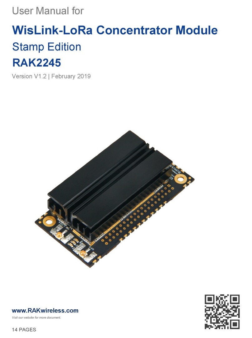
RAKwireless WisLink-LoRa RAK2245 Pi HAT User manual

2
RAK2245 Pi HAT
2
RAK2245 Pi HAT User Manual V1.2
Table of Contents
1 Overview..................................................................................................................................................... 4
1.1 Introduction......................................................................................................................................... 4
1.2 Main Features.................................................................................................................................... 4
1.3 Package Contents............................................................................................................................. 5
2 RAK2245 Pi HAT Board.......................................................................................................................... 5
2.1 Overview............................................................................................................................................. 5
2.2 Block Diagram.................................................................................................................................... 6
2.3 Operating Frequencies..................................................................................................................... 6
2.4 Pin Definition...................................................................................................................................... 7
2.5 Power Supply..................................................................................................................................... 8
2.6 SPI Interface.......................................................................................................................................8
2.7 UART and I2C.................................................................................................................................... 9
2.8 Digital IOs............................................................................................................................................9
2.9 LEDs.................................................................................................................................................... 9
2.10 Antenna RF Interface......................................................................................................................9
2.11 Electrical Characteristics................................................................................................................ 9
2.11.1 Absolute Maximum Rating.................................................................................................9
2.11.2 Maximum ESD...................................................................................................................10
2.11.3 Operating Conditions........................................................................................................10
2.11.4 Power Consumption......................................................................................................... 10
2.12 RF Characteristics.........................................................................................................................11
2.12.1 Transmitter RF Characteristics.......................................................................................11
2.12.2 Receiver RF Characteristics........................................................................................... 12
3 Source Codes..........................................................................................................................................13
4 Setup Network Server and Frequencies.......................................................................................... 13
5 Contact Information...............................................................................................................................13
6 Revision History..................................................................................................................................... 14
7 Document Summary..............................................................................................................................14

3
RAK2245 Pi HAT
3
RAK2245 Pi HAT User Manual V1.2
List of Tables
Table 1 | Operating Frequencies................................................................................................................6
Table 2 | Pin Definitions...............................................................................................................................8
Table 3 | Absolute Maximum Ratings........................................................................................................9
Table 4 | Maximum ESD Ratings.............................................................................................................10
Table 5 | Operation Temperature Range................................................................................................10
Table 6 | Power Consumption.................................................................................................................. 10
Table 7 | RF Output Power Level.............................................................................................................11
Table 8 | TX RF Characteristics............................................................................................................... 11
Table 9 | RX RF Characteristics...............................................................................................................12
List of Figures
Figure 1 | Package Contents...................................................................................................................... 5
Figure 2 | RAK2245 Pi HAT Overview...................................................................................................... 5
Figure 3 | RAK2245 Pi HAT Block Diagram............................................................................................. 6
Figure 4 | Raspberry Pi Connector Overview...........................................................................................7

4
RAK2245 Pi HAT
4
RAK2245 Pi HAT User Manual V1.2
1Overview
1.1 Introduction
RAK2245 Pi HAT is a module with Raspberry PI form factor. It can be plugged into
Raspberry PI such as Raspberry Pi 3 Model B+ as a complete RF front end of LoRa
gateway.It supports eight channels and is available for LoRaWAN global frequency
bands. The board is the smallest LoRaWAN gateway concentrator which integrates the
Ublox MAX-7Q GPS Module and heat sink.
The board can provide low data rate LoRa radio links in ultra-fast speed. It is powered
by a Semtech SX1301 transceiver concentrator that is capable of managing packets
from many remotely dispersed end-points. Two Semtech SX125X are integrated for RF
front end I/Q transceivers.
The RAK2245 Pi HAT is a complete and cost efficient LoRa gateway solution that can
help you develop a full LoRa system. This is an economical way to create different
solutions like smart grid, intelligent farm and other IoT applications. It is also ideal for
manufacturing small series that can expand into more applications.
Note: There are 2 type version with RAK2245 Series for the various interface in
GPS mdoule.
If you need use the Cellular Module (RAK2013 series), you must select the
RAK2245 series I2C version. If you don't need the Cellular Module, any version
can be working well. The default version is UART.
1.2 Main Features
Compatible with Raspberry Pi 3 Model B+ edition.
Integrated Ublox MAX-7Q GPS Module and heat sink.
SX1301 base band processor, emulates 49 x LoRa demodulators, 10 parallel
demodulation paths, supports 8 uplink / 1 downlink channels.
2 units of SX125x Tx/Rx front-ends for high/ low frequency.
Supports 5V power supply, integrated level conversion circuit.
TX power up to 27dBm, RX sensitivity down to -139dBm@SF12, BW 125KHz.
Supports latest LoRaWAN 1.0.2 protocol.
Supports global license-free frequency band (EU433, CN470, EU868, US915,
AS923, AU915, KR920, IN865 and AS920).

5
RAK2245 Pi HAT
5
RAK2245 Pi HAT User Manual V1.2
Supports SPI, UART, I2C interface.
1.3 Package Contents
Figure 1 | Package Contents
2RAK2245 Pi HAT Board
2.1 Overview
RAK2245 Pi HAT module with Raspberry Pi connector is shown below, it has outer
dimensions of 56.00 x 65.00 x 22.00 mm (±2mm).
Figure 2 | RAK2245 Pi HAT Overview
RAK2245 Pi HAT board
(1x)
iPEX Antenna
(1x)
GPS Active Antenna
(1x)

6
RAK2245 Pi HAT
6
RAK2245 Pi HAT User Manual V1.2
2.2 Block Diagram
The block diagram of RAK2245 Pi HAT shown as below.
Figure 3 | RAK2245 Pi HAT Block Diagram
The SX1301 digital baseband chip contains 10 programmable reception paths. Those
paths have differentiated levels of programmability and allow different use cases. It is
important to understand the differences between those demodulation paths to make the
best possible use from the system.
2.3 Operating Frequencies
The board supports all LoRaWAN frequency channels as below. Which is easy to
configure while building the firmware from the source code.
Region
Frequency ( MHz )
Europe
EU433, EU868
China
CN470
North America
US915
Asia
AS923, AS920
Australia
AU915
Korea
KR920
Indian
IN865
Table 1 | Operating Frequencies

7
RAK2245 Pi HAT
7
RAK2245 Pi HAT User Manual V1.2
2.4 Pin Definition
The pin connector of RAK2245 Pi HAT is located at the bottom side. Refer to the
diagram and table below for the description and numbering of each pins.
Figure 4 | Raspberry Pi Connector Overview
Pin
Name
Description
Pin
Name
Description
1
3.3V
3.3V Supply Voltage
2
+5V
+5V Supply Voltage
3
SDA
I2C_SDA (Connect to
GPS Module I2C_SDA)
4
+5V
+5V Supply Voltage
5
SCL
I2C_SCL (Connect to
GPS Module I2C_SCL)
6
GND
GND
7
NC
No Connection
8
UART_
RXD
It should be connected to
RASPBERRY PI’s
UART_TXD. This pin is
connected to GPS Module’s
UART_RXD internally.
9
GND
GND
10
UART_T
XD
It should be connected to
RASPBERRY PI’s
UART_RXD. This pin is
connected to GPS Module’s
UART_TXD internally.
11
RESET
SX1301 RESET (GPIO17
of RASPBERRY PI)
12
NC
No Connection
13
NC
No Connection
14
GND
GND
15
NC
No Connection
16
NC
No Connection
17
3.3V
3.3V Supply Voltage
18
NC
No Connection
Continuation:

8
RAK2245 Pi HAT
8
RAK2245 Pi HAT User Manual V1.2
Pin
Name
Description
Pin
Name
Description
19
SPI_M
OSI
It should be connected to
RASPBERRY PI’s SPI_
MOSI. This pin is
connected to SX1301’s
SPI_MOSI internally.
20
GND
GND
21
SPI_MI
SO
It should be connected to
RASPBERRY PI’s
SPI_MISO. This pin is
connected to SX1301’s
SPI_MISO internally.
22
NC
No Connection
23
SPI_CL
K
It should be connected to
RASPBERRY PI’s
SPI_SCLK. This pin is
connected to SX1301’s
SPI_CLK internally.
24
SPI_CS
It should be connected to
RASPBERRY PI’s
SPI_CE0. This pin is
connected to SX1301’s
SPI_CS internally.
25
GND
GND
26
NC
No Connection
27
ID_SD
I2C_SDA for HAT ID
EEPROM
28
ID_SC
I2C_SCL for HAT ID
EEPROM
29
NC
No Connection
30
GND
GND
31
NC
No Connection
32
NC
No Connection
33
RESET
_GPS
GPS Module reset PIN
(GPIO13 of Raspberry Pi)
34
GND
GND
35
STAND
BY_GP
S
GPS Module standby PIN
(GPIO19 of Raspberry Pi)
36
NC
No Connection
37
NC
No Connection
38
NC
No Connection
39
GND
GND
40
NC
No Connection
Table 2 | Pin Definitions
2.5 Power Supply
RAK2245 Pi HAT module is powered through 5V or 3.3V power pins.
2.6 SPI Interface
The pin connector provides an SPI connection which allows direct access to the
Sx1301 SPI interface. This gives the target system the possibility to use existing SPI
interfaces to communicate with the module.
Note: Please reset SX1301 via PIN 11 after turning on RAK2245 Pi HAT.

9
RAK2245 Pi HAT
9
RAK2245 Pi HAT User Manual V1.2
2.7 UART and I2C
UART and I2C connections are also included on the pin connector. These connections
allow direct access to the GPS module. The 1PPS is connected internally to SX1301.
2.8 Digital IOs
There are two digital IO PINs, which give the user an interface to reset the GPS module
or set it into standby mode.
2.9 LEDs
3 x Green LED for indicating the status of PWR, TX, RX.
2.10 Antenna RF Interface
The modules have two RF interfaces for LoRa and GPS antennas over the standard
UFL connectors (Hirose U. FL-R-SMT). It has a characteristic impedance of 50OHM
and supports both Tx and Rx via RF ports, providing the antenna interface.
2.11 Electrical Characteristics
The following are the electrical characteristics of RAK2245 Pi HAT. Please contact us if
you need other details and/or parameter for your project.
2.11.1 Absolute Maximum Rating
The values and range given below are all in accordance with Absolute
Maximum Rating System (IEC 134).
Parameter
Description
Min.
Typ.
Max.
Supply Voltage (VDD)
Input DC voltage
-0.3V
5.0V
5.5V
Operating Temperature
Temperature Range
-40°C
+85°C
RF Input Power
-15dBm
Table 3 | Absolute Maximum Ratings

10
RAK2245 Pi HAT
10
RAK2245 Pi HAT User Manual V1.2
Note: With RF output power level above +15 dBm a minimum distance to a
transmitter should be 1 m for avoiding too large input level.
2.11.2 Maximum ESD
The table below lists the maximum ESD.
Parameter
Min
Typical
Max
Remarks
ESD sensitivity for all
pins except ANT1
1 kV
Human Body Model according to
JESD22-A114
ESD sensitivity for
ANT1
1 kV
Human Body Model according to
JESD22-A114
ESD immunity for ANT1
4 kV
Contact Discharge according to
IEC 61000-4-2
8 kV
Air Discharge according to IEC
61000-4-2
Table 4 | Maximum ESD Ratings
Note: The module is an Electrostatic Sensitive Device and require special
precautions when handling.
2.11.3 Operating Conditions
The table below lists the operation temperature range.
Parameter
Min.
Typical
Max.
Remarks
Normal operating
temperature
–20°C
+25°C
+65°C
Fully functional and meets 3GPP
specifications
Extended operating
temperature
–40°C
+25°C
+85°C
RF performance may be affected if
outside the normal operating range, but
the module is still fully functional
Table 5 | Operation Temperature Range
2.11.4 Power Consumption
le 6 | Power Consumption
Mode
Condition
Min
Typical
Max
Active-Mode(TX)
TX enabled and RX disabled.
336mA
Active-Mode(RX )
TX disabled and RX enabled.
360mA

11
RAK2245 Pi HAT
11
RAK2245 Pi HAT User Manual V1.2
2.12 RF Characteristics
2.12.1 Transmitter RF Characteristics
The RAK2245 Pi HAT has an excellent transmitter performance. It is highly
recommended to use an optimized configuration for the power level
configuration, which is part of the HAL. This results in a mean RF output power
level and current consumption.
Table 7 | RF Output Power Level
T=25℃, VDD=5V (Typical) if nothing else stated.
8 | TX RF Characteristics
PA Control
DAC Control
MIX Control
DIG Gain
Nominal RF Power
Level [dBm]
0
3
8
0
-6
0
3
10
0
-3
0
3
14
0
0
1
3
9
3
4
1
3
8
0
8
1
3
9
0
10
1
3
11
0
12
1
3
12
0
14
1
3
13
0
16
2
3
12
0
17
2
3
13
0
19
2
3
14
0
20
3
3
10
0
0
3
3
11
0
0
3
3
12
0
25
3
3
13
0
26
3
3
14
0
27
Parameter
Condition
Min
Typ.
Max
Frequency Range
863 MHz
870 MHz
Modulation Techniques
FSK/LoRaTM
TX Frequency Variation vs.
Temperature
Power Level
Setting : 20
-3 KHz
+3 KHz
TX Power Variation vs.
Temperature
-5 dBm
+5 dBm
TX Power Variation
-1.5 dBm
+1.5 dBm

12
RAK2245 Pi HAT
12
RAK2245 Pi HAT User Manual V1.2
2.12.2 Receiver RF Characteristics
We recommended you to use optimized RSSI calibration values which is part
of HAL v3.1. For both Radio 1 and 2, the RSSI-offset should be set to -169.
The following table gives typical sensitivity level of RAK2245 Pi HAT.
Table 9 | RX RF Characteristics
Signal Bandwidth/[KHz]
Spreading Factor
Sensitivity/[dBm]
125
12
-139
125
7
-126
250
12
-136
250
7
-123
500
12
-134
500
7
-120

13
RAK2245 Pi HAT
13
RAK2245 Pi HAT User Manual V1.2
3Source Codes
Here is the open source code link:
https://github.com/RAKWireless/RAK2245-RAK831-LoRaGateway-RPi-Raspbian-OS
4Setup Network Server and Frequencies
The default Settings are Bulit-In LoraServer and EU868. If you get the others frequency,
you must setup it firstly. For the detailed setup steps, please refer to this documentation,
here is the link:
http://docs.rakwireless.com/en/LoRa/RAK2245-Pi-HAT/Application-
Notes/Get_Start_with_RAK2245_Pi_HAT_V2.4R.pdf
5Contact Information
Shenzhen Business
ken.yu@rakwireless.com
Room 506, Bldg B, New Compark, Pingshan First Road, Taoyuan Street, Nan
shan District, Shenzhen
Shenzhen Technical
steven.tang@rakwireless.com
0755-86108311
Room 506, Bldg B, New Compark, Pingshan First Road, Taoyuan Street, Nan
Shan District, Shenzhen

14
RAK2245 Pi HAT
14
RAK2245 Pi HAT User Manual V1.2
6Revision History
Revision
Description
Date
1.0
Initial version
2018-12-21
1.1
Modify Pin definition
2019-01-23
1.2
Add source codes chapter
2019-02-14
7Document Summary
Document Name: WisLink-LoRa RAK2245 Pi HAT User Manual
Product Name: LoRa Concentrator Module
Revision Number: V1.2
Prepared by
Checked by:
Approved by:
Jeff & Penn
Jeff
About RAKwireless:
RAKwireless is the pioneer in providing innovative and diverse cellular and LoRa
connectivity solutions for IoT edge devices. It's easy and modular design can be used in
different IoT applications and accelerate time-to-market .
For more information, please visit RAKwireless website at www.rakwireless.com.
Other manuals for WisLink-LoRa RAK2245 Pi HAT
1
Table of contents
Other RAKwireless Control Unit manuals
Popular Control Unit manuals by other brands

Jung
Jung 2072 TSM operating instructions

Conrad Electronic
Conrad Electronic GX106 operating instructions

Dometic
Dometic Radome ECU Installation, operation & maintenance manual

ABB
ABB i-bus EIB product manual

Signature Hardware
Signature Hardware RYLE 934425 quick start guide

Meinberg
Meinberg IMS VSI180 Setup guide