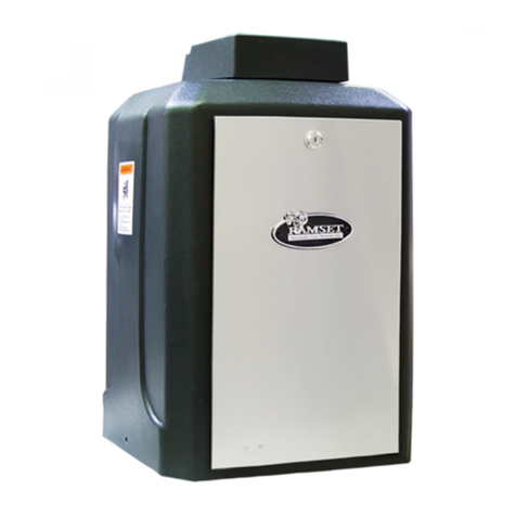
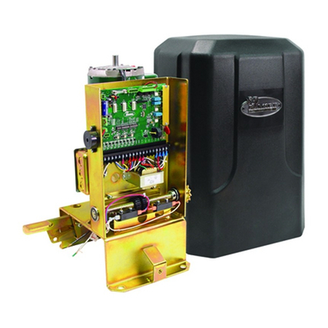
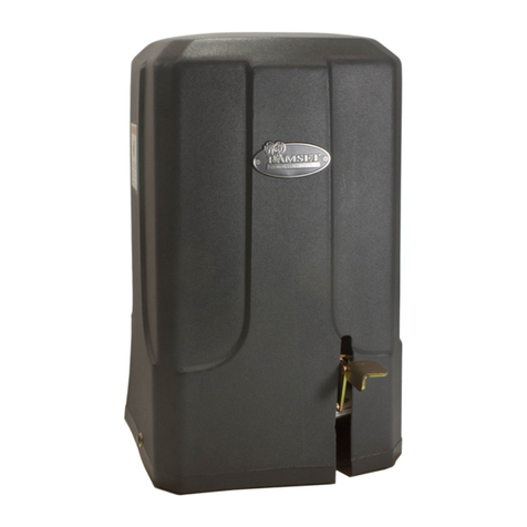
RAMSET ALL SECURE User manual

WARNING:
DO NOT INSTALL THIS GATE OPERATOR SYSTEM
UNLESS YOU ARE A TRAINED, EXPERIENCED GATE TECHNICIAN
IMPORTANT SAFETY REQUIREMENTS
• Read, understand & follow the instruction manual
• Never let children operate or play with gate controls. Keep the remote control
away from children.
• Always keep people and objects away from the gate. No one should cress the
path of the moving gate.
•• Test the vehicular gate operator monthly. The gate MUST reverse on contact
with a rigid object or stop when an object activates the non-contact
sensors. After adjusting the limit of travel, retest the vehicular gate
operator. Failure to adjust and retest the vehicular gate operator properly
can increase the risk of injury or death.
• Use the Emergency release only when power switch or circuit breaker has
been turned off. Using the emergency release during a power failure can
be a hazard if power is abruptly restored.
• KEEP GATES PROPERLY MAINTAINED. Read the owner’s manual. Have a
qualified service person make repairs to gate hardware.
• The entrance is for vehicles only. Pedestrians must use separate entrance.
• SAVE THESE INSTUCTIONS.
TABLE OF CONTENTS
1
2-3
4-5
6
7
8
99
10
11
12
13
14-15
16
17-1817-18
19-20
21
22-24
25-26
27
28
2929
Important safety requirements................................................................
Responsibilities of the installer/technician..............................................
Important safety requirementsby UL Standards.....................................
UL gate classification - Electrical Connection - Wire Gauge..................
General specifications............................................................................
Concrete pad location.............................................................................
Installation specifications........................................................................Installation specifications........................................................................
Rail location requirements......................................................................
Case mounting specifications.................................................................
Limit block location..................................................................................
Drive mounting specifications..................................................................
Plug connections.....................................................................................
Push button controls................................................................................
Dip switch configuration...........................................................................Dip switch configuration...........................................................................
Terminal strip connections.......................................................................
Entrapment and safety protection............................................................
Exploded view.........................................................................................
Parts list...................................................................................................
End user’s responsibilities.......................................................................
Emergency release procedure................................................................
Gate entrance warning - Placard safety..................................................Gate entrance warning - Placard safety..................................................
RESPONSIBILITIES OF THE INSTALLER/TECHNICIAN
** RAMSET GATE OPERATORS SHOULD ONLY BE INSTALLED,
MAINTAINED AND SERVICED BY QUALIFIED TECHNICIANS WHO HAVE
APPROPRIATE TRAINING WITH GATE OPERATORS**
INSTALLATION:
• READ AND UNDERSTAND THE INSTRUCTION MANUAL BEFORE ATTEMPTING ANY
INSTALLATION.
• USE THE PROPER OPERATOR. TAKE THE FOLLOWING INTO CONSIDERATION:
o CATEGORY (SWING, SLIDE OR OVERHEAD)
o TYPE (STANDARD, UPHILL, COMPACT , CANTILEVER …ETC)
- ALL MEASUREMENTS, SPECIFICATIONS AND CAPABILITIES IN THIS MANUAL
ARE FOR STANDARD INSTALLATIONS. ALL OTHER TYPES OF
INSTALLATIONS LOWER THE CAPABILITIES OF THE OPERATOR.
o GATE WEIGHT
o TRAVEL LENGTH
o CLASS (SEE PAGE 6)
• DO NOT EXCEED THE EQUIPMENTS SPECIFICATIONS AND CAPABILITIES.
SAFETY:
• SAFETY IS THE PRIMARY CONCERN WHEN INSTALLING A GATE OPERATOR.
• INSURE A SAFE AND PROPER INSTALLATION FOLLOWING ALL BUILDING, FIRE,
ELECTRICAL, PROPERTY MAINTENANCE, ASTM F 2200 AND UL 325 SAFETY
CODES.
• ONLY USE UL 325 COMPLIANT ACCESSORIES AND EQUIPMENT.
• ALL EXPOSED PINCH POINTS ARE ELIMINATED OR GUARDED.
• ALL EXPOSED ROLLERS ARE GUARDED.
• WHEN SERVICING A GATE OPERATOR ALWAYS PERFORM AN INSPECTION OF THE
ENTIRE INSTALLATION AND MAKE ANY AND ALL SUGGESTIONS, TO THE
PROPERTY OWNER, TO BRING THEIR SYSTEM INTO COMPLIANCE WITH THE
CURRENT UL STANDARD.
• WARNING SIGNS MUST BE PERMANENTLY AFFIXED TO THE GATE PANEL IN A
HIGHLY VISIBLE PLACE THAT CAN BE EASILY SEEN FROM BOTH SIDES OF THE
GATE.
• A SEPARATE ENTRANCE IS SUPPLIED FOR PEDESTRIANS. THE OPERATOR IS
INTENDED FOR INSTALLATION ONLY FOR GATES USED FOR VEHICLES.
• THE GATE MUST BE INSTALLED IN A LOCATION SO THAT ENOUGH CLEARANCE IS
SUPPLIED BETWEEN THE GATE AND ADJACENT STRUCTURES WHEN OPENING
AND CLOSING TO REDUCE THE RISK OF ENTRAPMENT.
2

RESPONSIBILITIES OF THE INSTALLER/TECHNICIAN cont.
SAFETY cont.:
• ALL CONTROLS MUST BE LOCATED AT LEAST 6 FEET AWAY FROM ANY PART OF
THE GATE OPERATOR OR MOVING GATE AT ALL TIMES.
• INTERIOR CONTROL STATIONS SHOULD BE INSTALLED SO THAT THE USER HAS A
DIRECT LINE OF SIGHT TO THE GATE AREA BEING CONTROLLED.
• PHOTOCELLS SHOULD BE INSTALLED WITHIN 5 INCHES FROM THE GATE PANEL
AND A MAXIMUM HEIGHT OF 27.5 INCHES.
• A PHOTOCELL IS A SAFETY DEVICE FOR PEDESTRIANS ONLY; VEHICLE
DETECTORS SHOULD ALWAYS BE USED FOR DETECTION OF MOTOR VEHICLES.
• NO SAFETY DEVICES SHOULD EVER BE BYPASSED, REMOVED OR OMITTED BY
THE INSTALLER/TECHNICIAN. A SIGNED WAIVER DOES NOT NULIFY THE
INSTALLER/TECHNICIANS LIABILITY DUE TO THE FACT THAT IT HAS NO
SUBSTANCE IN LITIGATION INVOLVING AN INJURED PARTY WHO DID NOT SIGN
THE WAIVER.
• IF YOU ARE INSTALLING THE OPERATOR ON A GATE THAT DID NOT HAVE AN
OPERATOR ON IT, THE GATE MUST CONFORM TO THE CURRENT ASTM F 2200
STANDARDS.
• IF YOU ARE INSTALLING THE OPERATOR ON A GATE THAT ALREADY HAD AN
OPERATOR ON IT, THE TECHNICIAN/INSTALLER SHOULD ADVISE THE
CUSTOMER OF THE UPGRADES THAT ARE NEEDED TO BRING THE GATE UP TO
THE CURRENT ASTM F 2200 STANDARDS.
• WHEN INSTALLING OR WORKING ON A GATE OPERATOR SYSTEM, ALWAYS MAKE
SURE THAT THE AREA AROUND YOU IS SECURE. USE CONES, YELLOW
CAUTION TAPE OR WHEN POSSIBLE, BLOCK OFF THE DRIVEWAY FROM
TRAFFIC.
• WHEN NECESSARY, INSTALL SURGE/LIGHTNING SUPPRESSION AND GROUND
RODS.
3

IMPORTANT SAFETY REQUIREMENTS BY UL STANDARDS
Prior to installation, the following must be observed: (UL 325.58.8.4)
a) Install the gate operator only when:
1) The operator is appropriate for the construction of the gate and the usage Class of the gate,
2) All openings of a horizontal slide gate are guarded or screened from the bottom of the gate
to a minimum of 6 feet (1.83m) above the ground to prevent a 2 ¼ inch (57.2 mm) diameter
sphere from passing through the openings anywhere in the gate, and in that portion of the
adjacent fence that the gate covers in the open position,
3) All exposed pinch points are eliminated or guarded, and
4) Guarding is supplied for exposed rollers.
b) The operator is intended for installation only on gates used for vehicles. Pedestrians must
be supplied with a separate access opening. The pedestrian access opening shall be
designed to promote pedestrian usage. Locate the gate such that persons will not come
in contact with the vehicular gate during the entire path of travel of the vehicular gate.
c) The gate must be installed in a location so that enough clearance is supplied between the gate
and adjacent structures when opening and closing to reduce the risk of entrapment. Swinging
gates shall not open into public access areas.
d) The gate must be properly installed and work freely in both directions prior to the installation of
the gate operator. Do not over-tighten the operator clutch or pressure relief valve to compensate
for a damaged gate.
e)e) For gate operator utilizing Type D protection:
1) The gate operator controls must be placed so that the user has sull view of the gate area
when the gate is moving,
2) The placard as required by 60.1.6 shall be placed adjacent to the controls,
3) An automatic closing device (such as a timer, loop sensor, or similar device) shall not be
employed, and
4) No other activation device shall be connected.
f)f) Controls intended for user activation must be located at least six feet (6’) away from any moving
part of the gate and where the user is prevented from reaching over, under, around or through
the gate to operate the controls.
***Exception: Emergency access controls only accessible by authorized personnel (e.g. fire,
police, EMS) may be placed at any location in the line-of-sight of the gate.
g) The Stop and/or Reset button must be located in the line-of-sight of the gate. Activation of the
reset control shall not cause the operator to start.
h)h) A minimum of two (2) WARNING SIGNS shall be installed, one on each side of the gate where
easily visible.
4

IMPORTANT SAFETY REQUIREMENTS BY UL STANDARDS
cont.
i) For gate operators utilizing a non-contact sensor in accordance with 31.1.1:
1) See instructions on the placement of non-contact sensors for each Type of application,
2) Care shall be exercised to reduce the risk of nuisance tripping, such as when a vehicle,
trips the sensor while the gate is still moving, and
3) One or more non-contact sensors shall be located where the risk of entrapment or
obstruction exists, such as the perimeter reachable by a moving gate or barrier.
j) For a gate operator utilizing a contact sensor in accordance with 31.1.1:
1) One or more contact sensors shall be located where the risk of entrapment or obstruction
exists, such as at the leading edge, trailing edge, and postmounted both inside and outside
of a vehicular horizontal slide gate.
2) One or more contact sensors shall be located at the bottom edge of a vehicular vertical lift
gate.
3) One or more contact sensors shall be located at the pinch point of a vehicular vertical pivot
gate.
4) A hardwired contact sensor shall be located and its wiring arranged so that the
communication between the sensor and the gate operator is not subjected to mechanical
damage.
5) A wireless device such as one that transmits radio frequency (RF) signals to the gate
operator for entrapment protection functions shall be located where the transmission of the
signals are not obstructed or impeded by building structures, natural landscaping or similar
obstruction. A wireless device shall function under the intended end-use conditions.
6) One or more contact sensors shall be located on the inside and outside leading edge of a
swing gate. Additionally, if the bottom edge of a swing gate is greater than 6 inches
(152 mm) above the ground at any point in its arc of travel, one or more contact sensors
shall be located on the bottom edge.
7) One or more contact sensors shall be located at the bottom edge of a vertical barrier (arm).
5

6
Voltage 12ga. 10ga. 8ga. 6ga.
115 VAC n/a Up to 150’ 150’ to 230’ 230’ - 400’
230 VAC Up to 350’ 600’ 850’ 1000’
MAXIMUM CONDUIT DISTANCE IN FEET USING COPPER
WIRE BY WIRE SIZE
RECOMMENDED WIRE GAUGE
INPUT POWER MOTOR HP FLA
115V Single 1 9.4 Amperes 9.9 Amperes
Phase
230V Single 1 5 Amperes
Phase
RECOMMENDED ELECTRICAL CONNECTION
A 3 wire, 120VAC electrical circuit with a 15 amps independent circuit breaker for single operator
and a 20 amps for Primary/Secondary. Ideally, the electrical conduits should exit the concrete
under the operator. Low voltage control wires must be run in a separate conduit to the operator.
NOTE: ALWAYS CONSULT AND FOLLOW ALL LOCAL BUILDING AND ELECTRICAL CODES
PRIOR TO INSTALLATION.
UL GATE CLASSIFICATION
Class I Residential Vehicular Gate Operator (3.19)
A vehicular gate operator (or system) intended for use in garages or parking areas associated
with a residence of one-to four single families.
Class II Commercial/General Access Vehicular Gate Operator (3.4)
A vehicular gate operator (or system) intended for use in a commercial location or building
such as a multi-family housing unit (five or more single family units), hotel, garages, retail
store or other buildings accessible by or servicing the general public.
Class III Industrial/Limited Access Vehicular Gate Operator(3.11)
A vehicular gate operator (or system) intended for use in an industrial location or building such
as a factory or loading dock area or other locations not accessible by or intended to service the
general public.
Class IV Restricted Access Vehicular Gate Operator (3.20)
A vehicular gate operator (or system) intended for use in a guarded industrial location or
building such as an airport security area or other restricted access locations not servicing the
general public, in which unauthorized access is prevented via supervision by security
personnel.

GENERAL SPECIFICATIONS
General specifications
WARNING Do not exceed the specifications.
The warranty on your unit will be void if the installation exceeds the recommended specifications
7
MODEL ALL SECURE
Max. Gate Length No Limit
Max. Applied Force 91 lbs
Cycles Continuous
Capacitor Aerovox 65μƒ, 240 V, 50/60 HZ, protected S 1000AFC
Application Commercial/ Industrial
Finish and Construction
Gold/Zinc plated H.R. Metal
Continuous Duty Motor 1 Hp, 1625 RPM, 115 VAC, 9.4 Amps, 60 Hz or 1 Hp, 1625 RPM,
230 VAC, 4.7 Amps, 60 Hz
Power Failure Release Hand Operated Release
Overall Dimensions H 22” - L 14½” - W 15” H 27” - L 16” - W 16½” H 27” - L 16” - W 16½”
Gate Travel Speed Approx. 1’ per sec
Shipping Weight xxx lbs

ALL SECURE PAD LOCATION SPECIFICATIONS
CONCRETE PAD LOCATION
Dimensions given for the pad location are based on a new pad, “right hand” installation with an
existing wall and gate location.
1. Use a CARPENTERS ANGLE to insure the concrete pad is square and parallel to the gate.
2. The leading edge (closest to the gate) should be placed to be 1 ¾” from the face of the
installed gate.
3. The right side of the concrete pad should be approximately 12 inches from the end of the
permanent fence or wall.
4. Concrete pad dimensions should be 30” long x 20” wide by 16” deep with the pad’s top
being level.
5. For drainage it is recommended that the concrete pad’s top be 6” above the road level.
MOUNTING STUD LOCATIONS
1. To determine the first mounting stud location begin at the top right corner of the concrete
pad. Using a carpenters angle measure down 2” from the leading edge (nearest the gate)
and 1 ¼” from the right side edge. Mark this location.
2. For the second stud location measure down 2” from the leading edge and 23 ½” from the
center of the fist stud location Mark this
location.
3. For the third stud location use the carpenters
angle to measure done 10 ½” from the first
location squaring the hole location to the first
two locations
4. For the last stud location use the carpenters
angle to measure done 10 ½” from the second
location squaring the hole location to the first
two locations.
When locations are complete a 23 ½” x 10 ½”
rectangular location pattern spaced 2 inches
from the leading edge.
5. Install 3/8-16 x 6” threaded studs in the marked
location making sure to install the studs deep
enough to leave 1” of threaded stud visible
above the surface of the concrete pad.
ELECTRICAL CONDUIT LOCATION
1. Electrical conduit locations are to be located on the left side of the concrete pad
coming up approximately 2 inches on center from the left edge of the pad as shown.
8

ALL SECURE INSTALLATION SPECIFICATION
WARNING: Do not exceed the specifications.
The warranty on your unit will be void if the installation exceeds the recommended specifications.
All Sliding Gate Operators are factory preset for (LH) Left
Hand Installations.
CONCRETE PAD CONSTRUCTION
Dimensions given for the pad are based on soil bearing
shear of 2000 P.S.F. These figures may have to be adjusted
depending on local soil conditions.
1. Construct form for mounting pad according to
dimensions shown in Figure 1 and 2
2. Locate mounting pad according to dimensions given in
illustration.
3. Level top edge of form.
4. Set reinforcing bars and wire mesh.
5. Mix concrete, pour mixture into form. Level and finish
surface after pouring is complete.
6. Allow pad to cure for 48 hours, and remove forms.
9

RAIL LOCATION REQUIREMENTS
RAIL SPECIFICATION:
Dimensions for the web are based on using a 4” x 4” x 1/4”
thick “Angle Iron” or equivalent with a 4” web section
intended as the contact area for the drive wheels of the ALL
SECURE unit.
1. The contact web of the drive rail must extend no less
than 4 inches from the gate for clearance.
2. Web sections, transitional radii, welds, and gussets
musts not extend more than 1 1/2” from the face of
the gate to avoid interference with the ALL SECURE
casing.
3. The Ideal height for the rail is 9 3/4” from the
underside of the drive rail to the top surface of the
ALL SECURE mounting pad.
RAIL PLACEMENT:
1. Clamp or otherwise secure the rail in the position
shown in Figure 2 with the bottom of the rail lining
up as shown.
2. Repeat this process in at least three separate
locations along the rail as it is attached to the
gate to ensure the rail is within tolerance along
the entire travel length of the gate.
3. Once the rail is in the correct position weld or
otherwise attach the rail to the gate as required
checking to be sure no attachment welds or
hardware interfere with the rail path.
4. If any problems in this process occur, please call
RAMSET customer service immediately.
10

CASE MOUNTING SPECIFICATION
RAIL SPECIFICATION:
1. Remove the ALL SECURE unit from
its shipping container taking care
not to scratch or damage the
finish.
2. Check the threaded stud height to
insure the height is no more than 1”
above the surface of the pad. Trim
stud height if needed.
3. Remove the drive assembly and
place the mounting slots of the
case over the 3/8-16 studs on the
mounting pad as shown.
4. Position the face of the case 1 ¾”
from the face of the gate as
required.
5. Apply “Locktite” and secure the
case with the 3/8=16 UNC washers
and nuts provided to a torque spec
of 27 Ft-lbs.
11

LIMIT BLOCK LOCATION
Installing the limit blocks and adjusting the limit switches is most easily done after the case has been
mounted and before the drive is placed into the case / enclosure. Final adjusting the stop blocks
should be done with the gate powered by the operator.
Limit Blocks
Left Limit Block Right Limit Block
SPECIFICATION:
Without slow stop.
Left hand operation is shown. Switch the words open and close for right hand operation.
1. Once installation is complete, set the slow dip switch down on the control board to the
off position.
2. Move the gate to its fully closed
position and make a vertical line on the
rail at the left edge of the enclosure.
Note: these instructions are based on a
medium weight gate travelling on a flat
surface. Inclines, variations in weight as
well as variations in rolling resistance
can substantially affect the coasting
distance of the gate. In instances
where the conditions differ substantially
it is recommended to run the gate near
the fully open and fully closed point to
determine the coasting distance. Run
12

the gate towards the fully opened position at full speed. Press the stop button a few feet
before fully opened position. Roughly measure the coasting distance from where the
stop button was pressed and where the gate came to rest. Use this as your distance to
mark the offset line.
3. Mark a vertical line “offset line” 12 inches
to the right of the previously drawn line.
(Alternatively you can use the coast
measurement as described above for the
offset distance.)
4. Place the leading (beveled) edge of the
left limit block on the vertical offset line
location towards the operator. Mark your
mounting hole locations in the middle of
the mounting slots.
5. Check to make sure the blocks will
engage the limit switch’s roller arms but
will not interfere with the All Secure Case.
6. Drill mounting holes using a 5/16” steel bit.
7. Mount the block using ¼-20 unc x 1 ½”
long carriage bolt, washers and nuts.
8. Check again for interference.
9. Adjust block forward or back as required
to calibrate the gate to stop at the
correct point.
10. Repeat steps 2 through 9 for the right side
limit block. Beveled edge of the right limit
block faces to the left.
12b

With slow stop.
Left hand operation is shown. Switch the words open and close for right hand operation.
Slow Stop Block (2)
1. Once installation is complete, set the slow dip
switch on the control board up to the on
position.
2. Run the gate to its fully closed position and make
a vertical line on the rail at the left edge of the
enclosure.
3. Mark a vertical line offset by 3 inches to the right
of the previously drawn line.
4. Mark a vertical line 2 feet to the right of the offset
line. This is the slow stop line used to position the
slow stop block.
5. Place the leading (beveled) edge of the left limit
block on the vertical offset line location towards
the operator. Mark your mounting hole locations
in the middle of the mounting slots.
6. Check to make sure the blocks will engage the
limit switch’s roller arms but will not interfere with
the All Secure Case.
7. Place the right edge of the slow stop block at the
slow stop block line. Mark your mounting hole
locations in the holes of the slow stop block.
8. Drill mounting holes using a 5/16” steel bit.
9. Mount the blocks using ¼-20 unc x 1 ½” long
carriage bolt, washers and nuts.
12c

10. Adjust the stop limit block forward or back as
required to calibrate the gate to stop at the
correct point.
11. Repeat steps 2 through 10 for the right side limit
block and slow stop block. Beveled edge of the
right limit block faces to the left. For step 3
change the distance from the offset line to the
stop block line from 2 feet to 3 feet.
Limit Switch Arm Length Adjustment
There are three limit switches located in the All Secure. They are mounted on a switch plate
attached to the rail side of the equipment enclosure. The entire switch plate can be
adjusted up and down by loosening the 2 mounting screws. In most cases this will not be
necessary. The left limit switch is triggered by the left limit block. The right limit switch is
triggered by the right limit block. The middle limit switch is triggered by the slow stop blocks
and are only used if the slow stop option is used.
1. Move the gate so that the left limit switch is
positioned in front of the left limit block. Adjust
the length of the limit switch arm so that it just
barely touches the surface of the block.
2. Move the gate so that the limit switch is clear of all blocks. Adjust
the length of the limit switch arm so that it extends an additional ¼
of an inch towards the rail. Securely tighten the limit arm adjusting
screw.
3. Repeated steps 1 and 2 for the right limit switch and right limit
block. If the slow stop option is used adjust the middle limit switch
using steps 1 and 2 with one of the slow stop blocks. If the slow
option is not used adjust the middle limit switch arm so that it is fully
retracted i.e. farthest from the rail.
12d

DRIVE MOUNTING SPECIFICATION
SPECIFICATION:
1. Lift and partially slide the drive unit into the
enclosure on the glide rails.
2. Remove shipping blocks on the right side of
the drive assembly, located between the
main mounting plate and the “C” bracket
at the right side of the drive unit.
3. Activate the locking clamp on the right side
“C” bracket to lock down the main plate of
the drive unit and push down the drive
wheels.
4. Disengage the toggle clamps on either side
of the idler wheel tower to free the idler
wheel
5. Lift drive into the rear of the case sliding the
chassis into position along the glide rails
6. Pass 3/8-16 UNC button-head socket cap screws through the square panel hole in the side
walls of the case and through the corresponding slot in the
drive unit.
7. Apply Locktite 242 to button-head socket cap screws .
8. Attach 3/8-16 UNC washers and nuts but do not tighten.
9. Remove the left side shipping blocks located between the
main mounting plate and the “C” brackets at each end of
the drive unit.
10. Lift drive unit until both lower drive wheel come into contact
with the drive rail and secure drive unit at that height by
tightening the 3/8-16 nuts to 27 Ft-lbs. Release the locking
clamp allowing the main plate of the drive unit to “float” free.
11. Latch idler wheel into place using the two over center clamps at the
top of the idler tower.
12. Adjust idler wheel tension bolt by tightening to 10 Ft-lbs.
13

N.C.
N.O.
COM
VS
VS
3-BUTTON
Common, Close,
Stop & Open. Used
with a 3-button
station
FOOT PEDAL
Foot pedal switch
input
PRIMARY/SECONDARY
CONNECTION
Synchronizes movement
between two gates.
3 wires (A, B & C)
MPE
(Monitored Photo Eye)
Mandatory Entrapment
protection photo eye
LOOP INPUTS
Loop wires - only used
with the plug-in RLD-24
detectors
RELAY CONNECTIONS
Lights, Alarms & Sirens
INPUT POWER
18VAC from the
transformer
PLUG IN DETECTORS
Used with the RLD-24
detectors only
14
PLUG CONNECTIONS
Never try to bypass or tamper with an
anti-entrapment safety device. This
may result in serious injury.
!

Constant Warn or Prewarn:
1. Wire from JP2-5 to Power supply (+)
2. Wire from JP2-6 to light/siren (+)
3. Wire from power supply (-) to light/siren (-)
* 24VAC, 1A max current draw.
Gate Open Light/Siren:
1. Wire from JP2-7 to Power supply (+)
2. Wire from JP2-8 to light/siren (+)
3. Wire from power supply (-) to light/siren (-)
* 24VAC, 1A max current draw.
WIRING DIAGRAMS
JP 13 - Monitored Photo Eye
Entrapment Protection:
1 - N.C. (Normally Closed)
2 - N.O. (Normally Opened)
3 - Common
4 - VS (Voltage Supply)
5 - VS (Voltage Supply)
**Every installation must have Monitored
Entrapment Protection.
Without it the operator will not function.
JP11 - Foot Pedal
1 - Common (Foot pedal switch)
2 - Normally Open (Foot pedal switch)
Only used on models with a foot pedal
(RAM 100, 1000, 5500, 300)
On the above mentioned operators, S7
must be in the ‘OFF’ position
On all other models, S7 must be in the ‘ON’
position
Factory wired to the foot pedal switch.
JP10 - Loop Inputs:
1 & 2 - Reverse loop wires
3 & 4 - Exit loop wires
5 & 6 - Phantom loop wires
Only used with the Ramset
RLD-24 & ILD-24s plug-in
loop detectors.
JP9 - Input Power:
1 - Common
2 - 18 VAC
Connection from external transformer to
power up the control board.
JP7 - Primary/Secondary:
1 - A 2 - B 3 - C
Synchronizes the operation between
two gates.
Three wire, shielded cable needed.
Align A to A, B to B & C to C from the
primary unit to the secondary unit.
JP3 - 3 Button:
1 - OP (open) - Normally open connection
2 - ST (stop) - Normally closed connection
3 - CL (close) - Normally open connection
4 - COM - (common)
Used with:
- A 3-button station.
- An anti-entrapment device where the gate
should stop and remained stopped.
To use the ST (stop) function, S7 - #1 must be
in the ‘OFF’ position.
JP2 - Relay Connectoins:
1 - 24VDC
2 - 24 VAC
3 - Do Not Use
4 - Fully Open - N.O.
5 - Relay Common
6 - Fully Closed - N.C.
7 & 8 - Constant Warn/Prewarn - N.O.
9 & 10 - ERD Alarm (factory wired)
All Relays are rated at 125VAC, 1A.
Used with:
- Lights or Sirens that show the gate is open.
- Constant Warn/Prewarn lights or sirens.
- Alarm that sounds when an obstruction is
sensed twice in a single travel.
See “WIRING DIAGRAMS”
PLUG CONNECTIONS
15

16
LEDs above the corresponding pushbut-
tons will light up to indicate the actions
of the motor.
FIGURE 15
Three pushbuttons are located under the dip switches for operation of the gate
(see Figure 15). The opening, stop and closing buttons can be utilized to set
limit switches and verify proper system operation when installing or servicing an
operator.
OPENING
Opens the gate.
STOP
Stops the gate.
CLOSING
Closes the Gate.
RESETTING THE E.R.D. (Electronic Reversing Device)
With power ‘on’ push all three pushbuttons for approximately 5 seconds. All
three LEDs should blink. Once they start blinking, let go of the three
pushbuttons.
*WARNING
- When pushing the three buttons, the gate can move at
any time. Always keep body parts and clothing clear of pulleys,
sprockets and all moving and electrical components in the operator
to help prevent serious injury.
PUSH BUTTON CONTROLS

17
Switch 7 8 Sensitivity
Off Off Most Sensitive
Off On Medium Sens.
On Off Low Sensitive
On On Least Sensitive
B5 - ONE PASS
OFF - Normal operation
ON - While the gate is opening, if the safety
input is triggered and then cleared, the
gate will immediately start closing. If the
safety input is then activated again,
before the gate is fully closed, the gate
will stop and stay at rest until the safety
loop is cleared. At any time if a valid
open signal is received, the gate will
open.
B6 - CLOSE DELAY
OFF - Normal operation
ON - Adds a 1 second delay before the gate
closes.
B7 - OPEN DELAY
OFF - Normal operation
ON - Adds a 1 second delay before the gate
opens.
B8 - RADIO CYCLE
OFF - Gate will open, if on the close limit,
and close, if on the open limit. If in
travel, the gate will always open or
continue to open.
ON - Gate will open, if on the close limit, and
close, if on the open limit. If in travel,
the gate will stop with the first command
and then reverse with a second
command.
DIP SWITCH S5 “C”
C1 - FULL REV ERD
OFF - Normal operation
ON - When closing, if the gate senses an
obstruction (ERD), the gate will stop
and reverse all the way to the fully open
limit.
C2 - SLOW
OFF - Normal Operation
ON - Adds a slow start when the gate opens
and a slow stop when the gate closes.
The slow stop is triggered by the slow
stop switch. (ONLY ON THE ALL
SECURE RAIL DRIVE OPERATOR)
C3, C4, C5 & C6
OFF - No function. These 4 switches should
not be turned to the ‘on’ position.
C7 & C8 - ERD 1 & ERD 2
DIP SWITCH S4 - “A”
A1, A2 & A3 - Automatic Timer to close gate
‘0’ is “off”, ‘1’ is “on”
A4 - LEFT/RIGHT
OFF - Left-hand installation
ON - Right-hand installation. Reverses the
motor and limit wires without moving
any wires.
DIP SWITCH S6 - “B”
B1 - PREWARN
OFF - Normal operation
ON - Triggers the relay on JP2, pins 7 & 8,
for 3 seconds before the gate moves in
any direction.
B2 - CONSTANT WARN
OFF - Normal operation
ON - Triggers the relay on JP2, pins 7 & 8
B3 - SECURE CLOSE
OFF - Normal operation
ON - When power is lost and then regained,
if all devices are clear and it’s safe, the
gate will close.
B4 - SECURE OPEN
OFF - Normal operation
ON - If the gate comes off of the limit without
a valid command, the gate will re-open.
Switch 1 2 3 Open Duration
0 0 0 disabled
0 0 1 00 seconds
0 1 0 05 seconds
0 1 1 10 seconds
1 0 0 15 seconds
1 0 1 30 seconds
1 1 0 45 seconds
1 1 1 60 seconds
DIP SWITCH CONFIGURATION
Table of contents
Other RAMSET Gate Opener manuals

RAMSET
RAMSET JET User manual

RAMSET
RAMSET RAM 100 User manual

RAMSET
RAMSET RAM 3000 UL User manual

RAMSET
RAMSET RAM 30 30 User manual

RAMSET
RAMSET RAM 5500 User manual

RAMSET
RAMSET RAM 300 User manual

RAMSET
RAMSET RAM 300 UL User manual

RAMSET
RAMSET RAM-30 UL User manual

RAMSET
RAMSET RAM 30 User manual

RAMSET
RAMSET RAM-5500 UL User manual
Popular Gate Opener manuals by other brands

Aprimatic
Aprimatic APRIBOX 600 Installation, use and maintenance instructions

All Security Equipment
All Security Equipment FAS-SLIDECH300BBUP user manual

FAAC
FAAC 746 ER CAT instruction manual

JOYTECH
JOYTECH PY500AC user manual

DoorKing
DoorKing 1175 Installation & owner's manual

Optima
Optima ESGO 4000 Installation instruction