Ramteq RH series User manual

READ THIS MANUAL
This manual contains important information for the use and safe operation of
your RAMTEQ®machine. FAILURE TO READ THIS MANUAL AND
FOLLOW ITS INSTRUCTIONS PRIOR TO OPERATING OR ATTEMPTING
ANY SERVICE OR MAINTENANCE PROCEDURE COULD RESULT IN
SERIOUS INJURY OR DEATH TO YOU OR OTHER PERSONS; ALSO
DAMAGE TO THE MACHINE OR TO OTHER PROPERTY.
Operator’sManual
BH SERIES
Electric Motor / Diesel fired
RAMTEQ®14275 NORTHWEST FREEWAY HOUSTON, TX 77040 PHONE: 713.983.6000 FAX: 713.983.6405 300-00011-01 8/05

OperatOr’sManual
RAMTEQ®14275 NORTHWEST FREEWAY HOUSTON, TX 77040 PHONE: 713.983.6000 FAX: 713.983.6405 300-00011-01 8/05
page 2
Section 1 operator’SManual
Unpacking....................................................................2
Safety inStrUctionS and WarningS.............................3
operating inStrUctionS...............................................4
Maintenance inStrUctionS...........................................5
Section 2 partS and Service Manual
partS diagraM.............................................................7
HoSe, Wand, & gUn.....................................................8
pUMpS...........................................................................8
BUrner aSSeMBly..........................................................9
control Box aSSeMBly.................................................9
plUMBing diagraMS....................................................10
Wiring diagraMS........................................................12
troUBleSHooting........................................................18
W
arranty
..............................................................19
Table of Contents
NOTICE
Information in this operator’s manual is subject to change without notice.
RAMTEQ SHALL NOT BE LIABLE FOR TECHNICAL OR EDITORIAL ERRORS OR OMISSIONS CONTAINED HEREIN. This operator’s manual
contains information protected by copyright. No part of this operator’s manual may be photocopied or reproduced in any form without
prior written consent from RAMTEQ
®
.
© RAMTEQ
®
, 2005
All rights reserved. Printed in USA.
INCLUDED PARTS
• Pallet
• Packing Material
Outer Box
• BH Series Machine
• Operator’s Manual
• Wand / Trigger Gun
• Nozzles
0º15º25º40º
• Hose 3/8” X 50’
• QC Hose Fittings
INSPECTION
Carefully unpack your new RAMTEQ equipment by removing the banding
and cardboard box from pallet. Remove the pressure washer from the
pallet and check for any physical damages that may have occurred during
shipment. Check for all parts specified and shown below.
Unpacking Instructions

OperatOr’sManual
RAMTEQ®14275 NORTHWEST FREEWAY HOUSTON, TX 77040 PHONE: 713.983.6000 FAX: 713.983.6405 300-00011-01 8/05
page 3
DO NOT operate this machine in areas where open flames are not permitted. DO NOT store or
use combustible materials on or near this machine. Use this equipment only in well ventilated
areas. Failure to follow this warning may cause carbon monoxide build up, fire or explosion, and
possible injury or death.
DO NOT operate this machine while under the influence of alcohol, drugs or while fatigued.
DO NOT direct discharge stream at yourself or others. Risk of injection or injury may occur.
Never put your hand or fingers over the spray tip. Do not try to stop or deflect leaks with your
hand or body. Always face nozzle and wand to the ground when testing.
DO NOT operate this machine WITHOUT wearing protective Eye Wear. Gloves, Hard Hat, Mask,
Ear Plugs & Steel Toe Work Boots are also recommended, DO NOT wear loose clothing. Keep
your body and clothing clear of the engine and discharge stream when the machine is running.
DO NOT tie back or block trigger gun in OPEN position. Never leave the pressure washer
unattended once you have started it. If you leave, shut down machine completely.
DO NOT overreach or stand on an unstable support while operating this machine. Maintain
good footing and balance.
DO NOT permit this machine to run while unattended or for extended periods of time with
trigger gun closed. Damage to pump may occur.
DO NOT operate this machine in an unsafe manner or around unsupervised children. Keep all
other personnel clear while operating this machine. This product should only be operated by
trained personnel.
DO NOT alter original factory settings prior to operating this machine. Risk of injury to yourself or
other persons may occur.
DO NOT remove hoses, guns, nozzles or any components while this machine is still hot or while
it is running.
DO NOT attempt to service this machine before reading the service manual.
DO NOT use water with a temperature over 140 degrees Fahrenheit
DO NOT use any electrical outlet that is not properly grounded or does not comply with all
federal, state, and local laws and/or electrical codes
DO NOT put diesel fuel in to a gasoline tank or gasoline into a diesel tank. Observe correct
markings on fuel tanks before filling.
DO NOT operate this machine without knowing how to stop and bleed water pressures. Know all
controls before using this machine.
DO NOT spray caustic, acids or abrasive fluids through this machine.
DO NOT permit water to freeze inside this machine. Pump and plumbing damage may occur.
Use only recommended RAMTEQ parts when servicing this machine.
RAMTEQ will not be held liable for any unauthorized modifications made to this
machine. Any such action will void the warranty.
Safety Guidelines
reaD tHIs FIrst!
FAILURE TO READ AND OBSERVE ALL
WARNING STATEMENTS COULD RESULT IN SEVERE BODILY
INJURY OR DEATH, POSSIBLE INJURY TO OTHER PERSONS,
DAMAGE TO MACHINE OR OTHER PROPERTY.
�
WARNING

OperatOr’sManual
RAMTEQ®14275 NORTHWEST FREEWAY HOUSTON, TX 77040 PHONE: 713.983.6000 FAX: 713.983.6405 300-00011-01 8/05
page 4
LOCATION GUIDELINES
Locate the machine on a solid and level surface so that engine and pump crankcase oil lubricate components properly.
Avoid areas where water can build up in the working area. Possible injury can occur caused by the surface becoming
slippery from water build up.
Locate the machine in a well-ventilated area and away from flammable materials or fumes. Be sure ventilation warnings
are observed. Keep pressure washer at least 18” away from flamable materials.
Locate the machine so the operator has easy access to the pressure washer and its controls. Locate the machine so that
it is protected from external damage.
To prevent damage and excessive hose wear, locate the pressure washer so that the hose does not cross traffic areas
STARTING THE MACHINE
Following the steps below will insure successful operation:
Read this manual completely before attempting to start the machine.
Check that the Motor/Burner switches are in the "OFF" position
Check the diesel tank and fill with a good grade of diesel fuel #1, #2 or kerosene.
Check the pump oil level and fill with SAE 30w non-detergent oil if needed.
Connect water hose to pump (or float tank if equipped). Turn on water source.
Connect the power cord to a properly grounded power source.
Attach high pressure hose to base of spray gun.
Install water nozzle at the end of wand, making sure it is clear of any obstructions.
Turn pump switch to “ON”
Pull trigger on gun until a steady stream of water comes out the nozzle. This purges any air in the system.
Check for leaks in the system and cycle trigger gun to insure bypass is adjusted correctly. Repair any leaks and correct
unloader adjustment if needed. Turn off machine before attempting any repairs.
Turn burner switch to "ON". Check gor buner ignition.
Adjust thermostat to desired temperature appropriate to the task. Maximum temperature setting may not be needed.
Insert detergent siphoning tube into a DOT approved container and open the metering valve for detergent application.
WASHING TECHNIQUES
Washing from bottom up increases dwell time of soap and lessens vertical streaks.
Turn soap metering valve “OFF” to purge system of soap
Rinsing with cold water from top down will retard detergent reaction which will enhance
the rinsing performance.
Wash at 30 to 60 degree angles to prevent splashback.
STOPPING THE MACHINE
Turn burner switch to “OFF”. Allow water to discharge for a few minutes while cooling down.
Turn pump switch to "OFF".
Disconnect water source.
Pull gun trigger to release water pressure from system.
Disconnect wand & gun assembly.
Wind up pressure hose on hose reel.
Operating Instructions

OperatOr’sManual
RAMTEQ®14275 NORTHWEST FREEWAY HOUSTON, TX 77040 PHONE: 713.983.6000 FAX: 713.983.6405 300-00011-01 8/05
page 5
MAINTENANCE PRECAUTIONS
Do not permit acidic, caustic or abrasive fluids to be pumped through system.
Periodically clean detergent inlet screen. This will ensure proper flow of water to the pump.
High mineral content in water may adversely affect your machine and may require the use of a water softener
to ensure proper operation.
NEVER run the pump dry under any circumtances. Doing so will cause exteme damage to the pump.
HEAT EXCHANGER COIL MAINTENANCE
Hard water conditions may eventually cause clogging in the heat exchanger coil if left unattended.
Scale deposits will compromise the heating efficiency and produce an unsafe condition over time.
It may be necessary to descale coil.
Scale buildup from certain detergents may eventually clog up the heat exchanger coil causing an
unsafe condition. Use only recommended detergents for better cleaning efficiency.
Black carbon deposits that collect on the outside wall of the heat exchanger coil may be a result of
using a poor grade of fuel or improper burner operation. Heating fuel should be void of water and
sediments to eliminate the possibility of sooting and compromising the efficiency of the coil.
FAILURE TO MAINTAIN HEAT EXCHANGER COIL MAY
RESULT IN A STEAM EXPLOSION WHICH MAY CAUSE
SERIOUS INJURY OR DEATH.
�
WARNING
Maintenance Instructions
MOVING, STORAGE
Place machine in covered area when not in use to protect from elements.Protect machine from
freezing in cold temperatures by storing in a heated location.
WINTERIZING
Non-float Tank Machines: To protect the machine from freezing temperatures while
storing or transporting, connect short length of garden hose (approximately 3 ft.) to
water inlet connection on machine. Remove the pressure nozzle from the wand and
insert the short garden hose end into a container of antifreeze. Place the wand into the
antifreeze container and start engine running machine until antifreeze appears from the
end of the wand. Turn engine “OFF” and replace pressure nozzle. Coil up hose and
move machine to storage area.
Float Tank Machines: Pour antifreeze into float tank and remove water nozzle from end
of wand and carefully insert into opening of float tank. Start machine and run until
antifreeze water mixture has circulated throughout the machine returning back to the
float tank.
PUMP MAINTENANCE
Fill crankcase to dot on oil gauge window per specifications with the specific oil created by the pump
manufacturer (i.e. General Pump Oil). Ensure the right oil for specific pump as it may vary.
Change oil after 40 Hour Break-in Period.
Change oil every Three Months or at 500 Hour Intervals thereafter.

OperatOr’sManual
RAMTEQ®14275 NORTHWEST FREEWAY HOUSTON, TX 77040 PHONE: 713.983.6000 FAX: 713.983.6405 300-00011-01 8/05
page 6
ELECTRODE SETTINGS
Inspection of all wires, spring
contacts and electrodes should
be done periodically.
OIL BURNER AIR BAND ADJUSTMENT
RAMTEQ
®
sets oil burners at sea level. Air bands may need adjustment at higher elevations to offer
enhanced performance of the burner and extended life of the machine.
Adjustment of burner is done with pump motor and thermostat
set to maximum. Loosen locking screw on air band, then close
band until black smoke vents up exhaust vent. Take careful note
of air band position when black smoke is first noticed. Slowly
open air band until white smoke vents, then turn air band halfway
back to where black smoke was first noted. Tighten air band
locking screw. When properly set, the unit should NOT have either
"black" smoke or "white" smoke during operation.
IF BLACK OR WHITE SMOKE VENTS FROM EXHAUST
PORT UPON STARTING EQUIPMENT, DISCONTINUE USE
AND ADJUST AIR BANDS BEFORE RESTARTING.
�
WARNING
Maintenance Instructions
All RAMTEQ machines have the unloader
correctly set at the the factory. Setting an
unloader is a difficult job without the proper
equipment and training. Should the need arise
to change the unloader settings, please contact
your local distributor.
UNLOADER ADJUSTMENT
CHANGING THE UNLOADER SETTINGS WITHOUT THE PROPER
EQUIPMENT AND TRAINING MAY RESULT IN NON-WARRANTY
DAMAGE TO THE PUMP.
�
WARNING
Sutner
Unloader

OperatOr’sManual
RAMTEQ®14275 NORTHWEST FREEWAY HOUSTON, TX 77040 PHONE: 713.983.6000 FAX: 713.983.6405 300-00011-01 8/05
page 7
Ref.# Part # Description Qty.
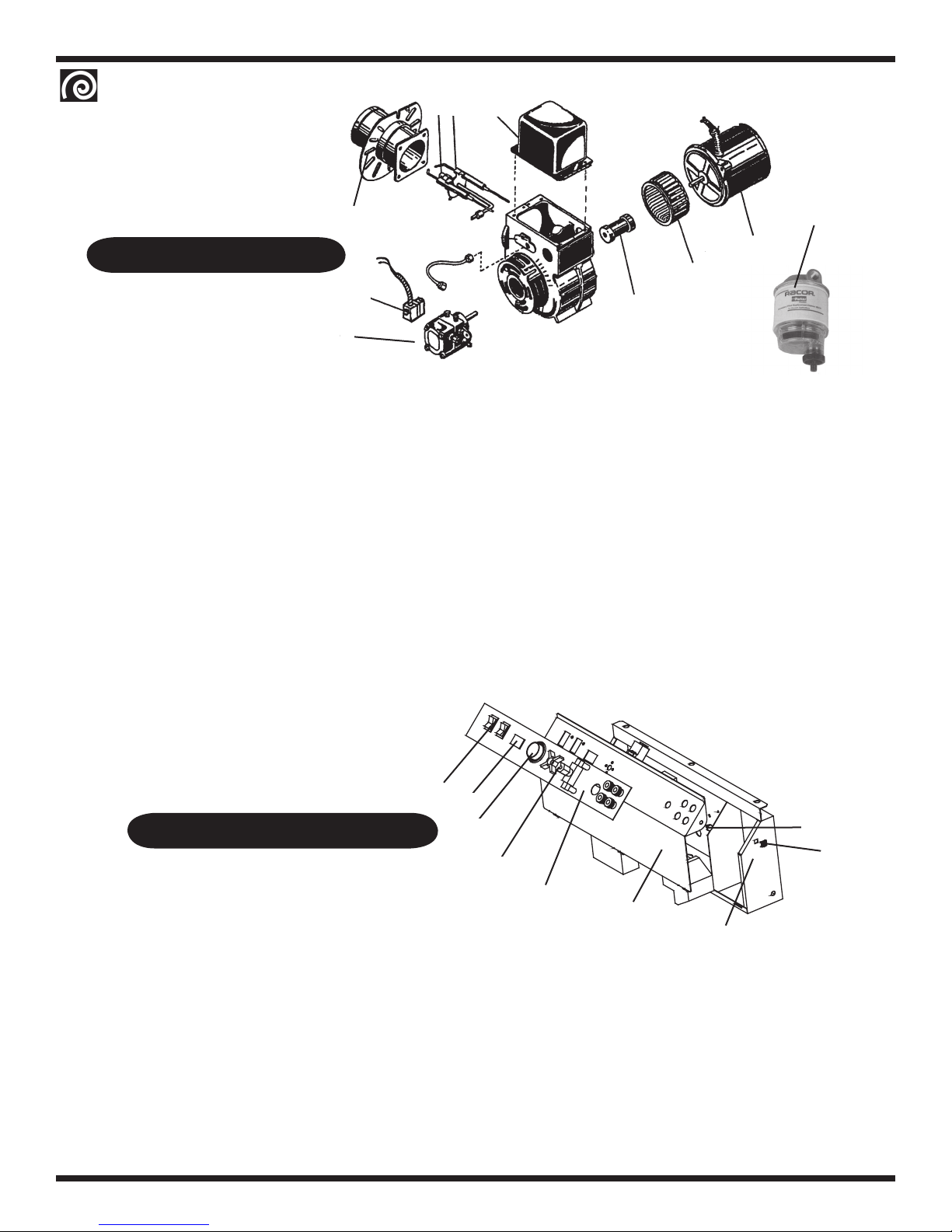
1 180-00043-01 Panel, Closeout Front/Back 1
2a 200-00009-01 Motor, 5.0hp 208/230/1 Baldor L1410T 1
2b 200-00005-01 Motor, 5.0hp 208/230/3 Baldor M3218T 1
2c 200-00012-01 Motor, 6.0hp 208/230/1 1
2d 200-00006-01 Motor, 7.5hp 208/230/3 Baldor M3311T 1
2e 200-00007-01 Motor, 10.0hp 230/460/3 Baldor M3313T 1
3 180-00023-01
Plate, Power 1
4a 170-00005-01 Wheel, Casters Fixed 8” 2
4b 170-00004-01 Wheel, Casters Swivel 8” 2
5 170-00002-01 Wheel, Caster Swivel 6” 2
6 170-00003-01 Wheel, Pneumatic Split Rim 2
7 180-00052-01 Bracket, Four Wheel Configuration 2/4
8 175-00001-02 Axle, Two and Four Wheel Configuration 2/4
9 516-00001-01
Bushing, Wheel Collar, 5/8” 4
10 050-00008-01 Chassis, BV and BH Series 1
11 180-00056-01 Plate, Closeout Top 1
12 190-00002-01 Fuel, Tank 9 Gallon Green 1
13 140-00001-01 Cap, Fuel Gauge Diesel Black 1
14 180-00022-01 Handle, Frame BH Series 1
15 180-00044-01 Bracket, Coil Horizontal Rest 1
16 155-00005-01 Coil, Large Diesel Fired 1
191-00006-01 Insulation Blanket 1”x24”w, 4# (not shown) 1
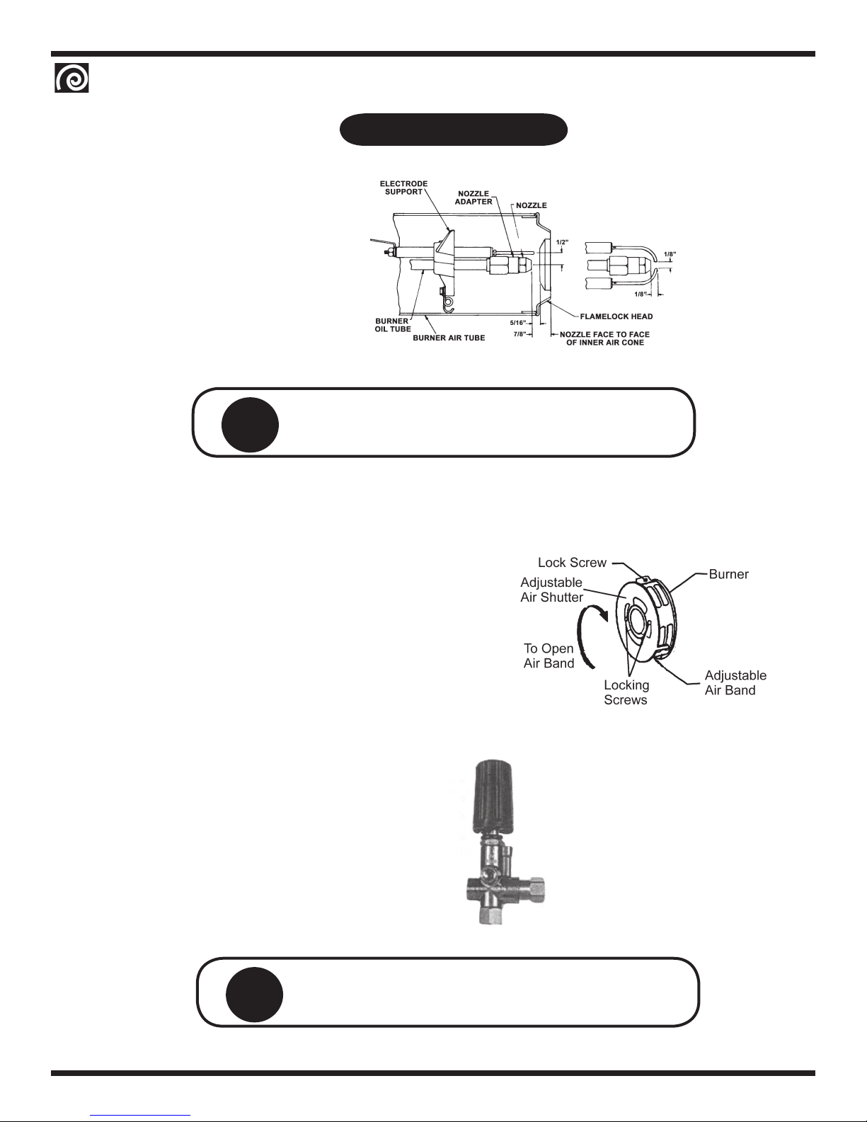
17a 250-00002-01 Burner Assembly (208/230v) 1
17b 250-00003-01 Burner Assembly (110v) 460 volt machines 1
18 180-00025-01 Cap, SS End Burner 1
19 191-00001-01 Insulation, Burner 17.65”x3.44” 1
20 180-00018-01 Shell, SS Outer Top 1
21 191-00002-01 Insulation, Exhaust 17.55”x1” 1
22 180-00024-01 Cap, End Closed 1
23 180-00017-01 Shell, SS Outer Bottom 1
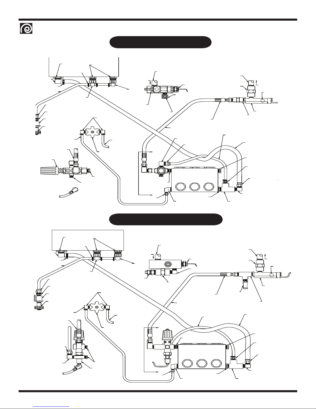
24 055-00030-01 Float Tank Assembly 1
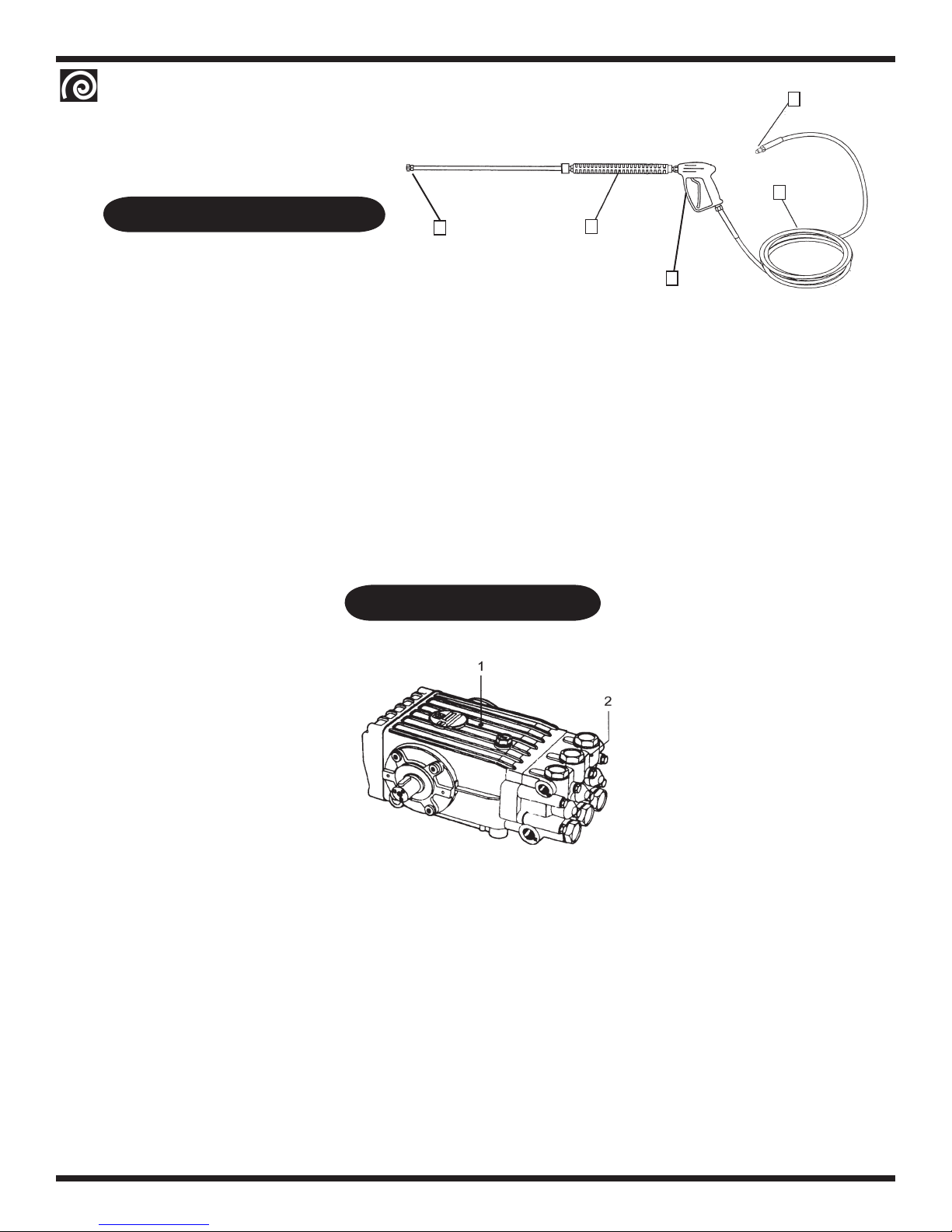
25a 220-00004-01 Pump, General T1011-R (BH 500,BH 600) 1
25b 220-00009-01 Pump, General TS2021-R (BH 750 / BH 1000) 1
26 180-00048-01 Bracket, Pump Belt Tension (not shown) 1
584-00003-11 Pulley, 2BK50H (BH 500,BH600) 1
584-00002-09 Pulley, 2BK80H (BH 500,BH600) 1
516-00002-03 Bushing, SP Split Taper, H 1-1/8” 1
516-00002-01 Bushing, SP Split Taper H-24mm 1
586-00004-04 Belt, BX36 (BH 500; BH 750) 2
584-00002-08 Pulley, 2BK45H (BH 750) 1
584-00002-09 Pulley, 2BK80H (BH 750) 1
516-00002-04 Bushing, SP Split Taper, H 1-3/8” (BH 500/600/750/1000) 1
584-00002-04 Pulley, 2BK57H (BH 1000) 1
584-00002-06 Pulley, 2BK70H (BH 1000) 1
586-00004-04 Belt, BX36 (BH 1000) 2
13
23
14
17
19
18 20
22
24
1
2
3
4
5
8
7
10
Exploded
view on
page 9.
25
26
15
BH Parts Diagram 21
12
11
6
9

OperatOr’sManual
RAMTEQ®14275 NORTHWEST FREEWAY HOUSTON, TX 77040 PHONE: 713.983.6000 FAX: 713.983.6405 300-00011-01 8/05
page 8
Ref.# Part # Description Qty.
1a 270-00028-01 Nozzle, Water #5.5 0º (BH 500,600) 1
1b 270-00028-02 Nozzle, Water #5.5 15º(BH 500,600) 1
1c 270-00028-03 Nozzle, Water #5.5 25º(BH 500,600) 1
1d 270-00028-04 Nozzle, Water #5.5 40º(BH 500,600) 1
1e 270-00025-01 Nozzle, Water #4.0 0º (BH 750) 1
1f 270-00025-02 Nozzle, Water #4.0 15º(BH 750) 1
1g 270-00025-03 Nozzle, Water #4.0 25º(BH 750) 1
1h 270-00025-04 Nozzle, Water #4.0 40º( BH 750) 1
1i 270-00028-01 Nozzle, Water #5.5 0º ( BH 1000) 1
1j 270-00028-02 Nozzle, Water #5.5 15º( BH 1000) 1
1k 270-00028-03 Nozzle, Water #5.5 25º(BH 1000) 1
1m 270-00028-04 Nozzle, Water #5.5 40º(BH 1000) 1
2 265-00001-01 36” Wand, Insulated 1
3 275-00001-01 ST1500 Trigger Gun 1
4 552-00004-03 3/8” Quick Connect, Female Plug 1
5 284-00001-01 Hose 3/8” X 50” R-1 Swivel Ends 1
BH Belt Drive Pump
Hose, Wand & Gun
General Pump T1011-R, T2011-R, TS2021-R Triplex Plunger Pump
1
3
4
5
2
Ref.# Part # Description Qty.
1 220-00004-01 T1011 Triplex Plunger Pump Complete (BH 500,600) 1
1a 220-00009-01 TS2021 Triplex Plunger Pump Complete (BH 1000) 1
2 221-00001-06 Manifold, Brass Head T1011 (BH 500,600) 1
2a 221-00001-02 Manifold, nickle plated Head TS2021 (BH 750, 1000) 1
Pump Repair Kits
Part # Description Qty.
221-00002-01 Check Valve Assembly Kit #1 (All BH Series) 6
221-00018-01 Oil Seal Kit #2 (All BH Series) 3
221-00019-01 Oil Ring and Valve Cap Kit # 4 (T1011) 6
221-00026-01 Oil Ring and Valve Cap Kit #5 (T2011) 6
221-00010-01 Head Packing Complete Kit #28 (All BH Series) 1

OperatOr’sManual
RAMTEQ®14275 NORTHWEST FREEWAY HOUSTON, TX 77040 PHONE: 713.983.6000 FAX: 713.983.6405 300-00011-01 8/05
page 9
Ref.# Part # Description Qty.
1 571-00002-01 Hour Meter 1
2 450-00001-01 Pump/Burner Switch On/Off 2
3 573-00001-01 Thermostat Assembly 1
4 505-00001-01 1/4 - 20 Bolt 2
5 508-00002-02 Tinnerman 2
6 180-00029-01 Control Box 1
7 180-00028-01 Control Box Panel 1
8 305-00016-01 Label,Control Box 1
9 579-00006-01 Valve, Metering 1
6
7
8
1
1a
2
345
BH Burner Assembly
BH Control Box Assemblies
9
Ref.# Part # Description Qty
1 251-00001-01 Fuel Pump w/ Solenoid 115v 1
2 256-00001-02 Main Burner Gasket 1
3 245-00012-16 Nozzle 1
4 258-00002-02 Electrode Pair 1 pr
5 252-00001-03 Transformer 115v 1
5a 252-00001-02 Transformer 208/230v 1
6 253-00001-02 Coupling 1
7 253-00002-02 Fan Wheel 6.25”x4.0” 1
8 254-00001-03 Motor 115v/60/1 1
8a 254-00001-02 Motor 208/230v/60/1 1
9 577-00003-01 Filter, Fuel Inline Racor 1
578-00001-01 Element, Fuel Filter, Racor 1
280-00003-01 Hose, Inlet/Outlet Fuel Line (not shown) 2
556-00001-01 Clamp, Hose (not shown) 2
Burner Assembly Complete
250-00003-01 EH-H-115 (BH 500, 750, 1000)
250-00002-01 EH-H-230 (BH 500, 600, 750, 1000)
4
2
8
7
1
3
5
6
9

OperatOr’sManual
RAMTEQ®14275 NORTHWEST FREEWAY HOUSTON, TX 77040 PHONE: 713.983.6000 FAX: 713.983.6405 300-00011-01 8/05
page 10
ELBOW, POLYPROPYLENE
3/8 BARB X 3/8 BARB
1/4 NPTM X 1/4 BARB
ELBOW, BRASS (2 PL.)
FLOAT VALVE (2 PL.)
METERING VALVE
3/8 NPTM SWIVEL X 3/8 HOSE
HOSE END, HIGH PRESSURE
UNLOADER
SUTTNER, ST-280
SECTION AA
1/4 NPT PLUG
3/8 NPT PLUG
ELBOW, BRASS
1/2 NPT X 1/2 BARB
LOW PRESSURE HOSE
3/8 I.D. X 7"
#8 JIC FEMALE X 3/8 BARB
GARDEN HOSE CONNECTOR
COUPLER, FRAME MOUNTED
LOW PRESSURE HOSE
1/4" I.D. X 32"
3/4 SWIVEL X 3/8 NPTM
HOSE END, SWIVEL
3/8 NPTF X 3/8 NPTF
CONNECTOR, BRASS
#8 FLARE X 3/8 NPTM
1/2 NPTF I.D.
3/8 BARB X 3/8 BARB X 3/8 BARB
Ø1/4 - 5/8 (6 PL.)
TEE, POLYPROPYLENE
CLAMP BAND
BULKHEAD FITTING
Ø0.4 - 0.9
CLAMP BAND
FLOAT TANK
1/2 I.D. X 22"
HOSE END, SWIVEL
3/8 NPT PLUG
3/8 BARB X 3/8 NPTM
CONNECTOR, BRASS
HOSE END, SWIVEL
#8 JIC FEMALE X 1/2 BARB
ELBOW, BRASS
#8 FLARE X 3/8 NPTM
1/2 NPTM X #4 FLARE
ELBOW, BRASS
A
#4 JIC FEMALE X 1/4 BARB
HOSE END, SWIVEL
A
NIPPLE, PLATED STEEL
3/8 NPT CLOSE HEX
1/2 NPTM X 3/8 NPTF
BUSHING, BRASS
TEE, BRASS
3/8 NPT STREET
PUMP
#8 JIC FEMALE X 3/8 BARB
MODELS:
LOW PRESSURE HOSE
FLOW SWITCH
ELBOW, PLATED STEEL
3/8 NPT STREET
NIPPLE, GALVANIZED STEEL
THERMOSTAT
3/8 I.D. X 31.5"
3/8 NPTM SWIVEL X 3/8 HOSE
HOSE END, HIGH PRESSURE
HIGH PRESSURE HOSE
ELBOW, BRASS
#8 FLARE X 1/4 NPTM
3/8 NPTM X 3/8 MALE
QUICK CONNECT COUPLER
JE ADAMS 7468 (3500 PSI)
1/4" I.D. TUBE X 50"
DETERGENT LINE
RELIEF VALVE
FROM COIL OUTLET
1/2 NPT X 2.5"
COUPLER, PLATED STEEL
3/8 NPTF X 3/8 NPTF
LOW PRESSURE HOSE
3/8 I.D. X 11"
1/2 NPT X 2.5"
NIPPLE, GALVANIZED STEEL
1/2 NPTF X 3/8 NPTF
COUPLER, PLATED STEEL TO COIL INLET
1/4 NPT PLUG
BH500-06
BH500-02
BH500-05
BH500-01
BH500-09
BH500-10
ELBOW, POLYPROPYLENE
3/8 BARB X 3/8 BARB
ELBOW, BRASS (2 PL.)
1/4 NPTM X 1/4 BARB
1/4" I.D. TUBE X 50"
DETERGENT LINE
RUPTURE DISK
METERING VALVE
3/8 NPTM SWIVEL X 3/8 HOSE
#8 JIC FEMALE X 3/8 BARB
HOSE END, SWIVEL
#8 FLARE X 1/4 NPTM
ELBOW, BRASS
HOSE END, HIGH PRESSURE
SECTION AA
SUTTNER, ST-261
1/4 NPT PLUG (2 PL.)
UNLOADER
LOW PRESSURE HOSE
CLAMP BAND
1/2 NPT X 1/2 BARB
ELBOW, BRASS
Ø0.4 - 0.9
LOW PRESSURE HOSE
#8 FLARE X 3/8 NPTM
CONNECTOR, BRASS
#8 JIC FEMALE X 3/8 BARB
HOSE END, SWIVEL
COUPLER, FRAME MOUNTED
3/8 NPTF X 3/8 NPTF
GARDEN HOSE CONNECTOR
3/4 SWIVEL X 3/8 NPTM
1/4" I.D. X 32"
3/8 I.D. X 7"
3/8 BARB X 3/8 BARB X 3/8 BARB
BULKHEAD FITTING
TEE, POLYPROPYLENE
FLOAT TANK
Ø1/4 - 5/8 (6 PL.)
CLAMP BAND
1/2 NPTF I.D. FLOAT VALVE (2 PL.)
1/2 I.D. X 22"
HOSE END, SWIVEL
CONNECTOR, BRASS
3/8 BARB X 3/8 NPTM
#8 JIC FEMALE X 1/2 BARB
#8 FLARE X 3/8 NPTM
PUMP
NIPPLE, PLATED STEEL
3/8 NPT CLOSE HEX
ELBOW, BRASS
BUSHING, BRASS
1/2 NPTM X 3/8 NPTF
1/2 NPTM X #4 FLARE
HOSE END, SWIVEL
#4 JIC FEMALE X 1/4 BARB
A
A
TEE, BRASS
3/8 NPT STREET
ELBOW, BRASS
LOW PRESSURE HOSE
3/8 I.D. X 14"
3/8 NPT PLUG
MODELS:
1/4 NPT PLUG
TO COIL INLET
FLOW SWITCH
LOW PRESSURE HOSE
QUICK CONNECT COUPLER
3/8 NPTM X 3/8 MALE
ELBOW, PLATED STEEL
3/8 NPTM X 3/8 NPTM
THERMOSTAT
HIGH PRESSURE HOSE
HOSE END, HIGH PRESSURE
3/8 NPTM SWIVEL X 3/8 HOSE
COUPLER, PLATED STEEL
1/2 NPTF X 3/8 NPTF
3/8 I.D. X 31.5"
NIPPLE, GALVANIZED STEEL
1/2 NPT X 2.5"
FROM COIL OUTLET
(ORANGE SPRING)
POP-OFF VALVE
GIANT #22532A
TEE, PLATED STEEL
3/8 NPT BOX
1/2 NPTF X 3/8 NPTF
NIPPLE, GALVANIZED STEEL
COUPLER, PLATED STEEL
1/2 NPT X 2.5" BH500-11
BH500-12
BH500-08
BH500-07
BH500-04
BH500-03
BVE 500, 600 Base Plumbing
BVE 500, 600 Upgrade Plumbing

OperatOr’sManual
RAMTEQ®14275 NORTHWEST FREEWAY HOUSTON, TX 77040 PHONE: 713.983.6000 FAX: 713.983.6405 300-00011-01 8/05
page 11
FROM COIL OUTLET
1/4" I.D. TUBE X 50"
DETERGENT LINE
RUPTURE DISK
#4 JIC FEMALE X 1/4 BARB
3/8 NPTM SWIVEL X 3/8 HOSE
#8 JIC FEMALE X 3/8 BARB
HOSE END, SWIVEL
#8 FLARE X 1/4 NPTM
ELBOW, BRASS
HOSE END, HIGH PRESSURE
UNLOADER
SUTTNER, ST-261
SECTION AA
1/4 NPT PLUG (2 PL.)
METERING VALVE
LOW PRESSURE HOSE
Ø0.4 - 0.9
CLAMP BAND
1/4" I.D. X 32"
#8 JIC FEMALE X 3/8 BARB
COUPLER, FRAME MOUNTED
3/4 SWIVEL X 3/8 NPTM
GARDEN HOSE CONNECTOR
LOW PRESSURE HOSE
HOSE END, SWIVEL
3/8 NPTF X 3/8 NPTF
CONNECTOR, BRASS
#8 FLARE X 3/8 NPTM
ELBOW, BRASS
1/2 NPT X 1/2 BARB
3/8 I.D. X 7"
3/8 BARB X 3/8 BARB X 3/8 BARB
1/4 NPTM X 1/4 BARB
ELBOW, BRASS (2 PL.)
TEE, POLYPROPYLENE
BULKHEAD FITTING
Ø1/4 - 5/8 (6 PL.)
CLAMP BAND
1/2 NPTF I.D.
FLOAT TANK
ELBOW, POLYPROPYLENE
3/8 BARB X 3/8 BARB
FLOAT VALVE (2 PL.)
1/2 I.D. X 22"
3/8 BARB X 3/8 NPTM
CONNECTOR, BRASS
#8 JIC FEMALE X 1/2 BARB
HOSE END, SWIVEL
LOW PRESSURE HOSE
1/2 NPTM X 3/8 NPTF
BUSHING, BRASS
1/2 NPTM X #4 FLARE
3/8 NPT CLOSE HEX
NIPPLE, PLATED STEEL
3/8 I.D. X 14"
HOSE END, SWIVEL
A
ELBOW, BRASS
A
PUMP
3/8 NPT STREET
TEE, BRASS
#8 FLARE X 3/8 NPTM
ELBOW, BRASS
3/8 NPT PLUG
BH1000
BH750-12
BH750-11
BH750-08
BH750-07
TO COIL INLET
1/4 NPT PLUG
FLOW SWITCH
THERMOSTAT
3/8 NPTM X 3/8 NPTM
ELBOW, PLATED STEEL
HOSE END, HIGH PRESSURE
3/8 NPTM SWIVEL X 3/8 HOSE
HIGH PRESSURE HOSE
1/2 NPTF X 3/8 NPTF
COUPLER, PLATED STEEL
3/8 I.D. X 31.5"
1/2 NPT X 2.5"
NIPPLE, GALVANIZED STEEL
3/8 NPTM X 3/8 MALE
QUICK CONNECT COUPLER
TEE, PLATED STEEL
GIANT #22533A
(BLUE SPRING)
POP-OFF VALVE
LOW PRESSURE HOSE
3/8 NPT BOX
NIPPLE, GALVANIZED STEEL
COUPLER, PLATED STEEL
1/2 NPT X 2.5"
1/2 NPTF X 3/8 NPTF
MODELS:
HOSE END, SWIVEL 1/2 I.D. X 22"
#4 JIC FEMALE X 1/4 BARB
HOSE END, HIGH PRESSURE
3/8 NPTM SWIVEL X 3/8 HOSE
SUTTNER, ST-280
UNLOADER
SECTION AA
1/4 NPT PLUG
3/8 NPT PLUG
METERING VALVE
#8 JIC FEMALE X 1/2 BARB
HOSE END, SWIVEL
CONNECTOR, BRASS
3/8 BARB X 3/8 NPTM
#8 JIC FEMALE X 3/8 BARB
BUSHING, BRASS
1/2 NPTM X 3/8 NPTF
1/2 NPTM X #4 FLARE
HOSE END, SWIVEL
A
ELBOW, BRASS
NIPPLE, PLATED STEEL
3/8 NPT CLOSE HEX
A
PUMP
TEE, BRASS
3/8 NPT STREET
ELBOW, BRASS
#8 FLARE X 3/8 NPTM
3/8 NPT PLUG
FROM COIL OUTLET
DETERGENT LINE
1/4" I.D. TUBE X 50"
Ø0.4 - 0.9
LOW PRESSURE HOSE
CLAMP BAND
HOSE END, SWIVEL
1/4" I.D. X 32"
LOW PRESSURE HOSE
#8 FLARE X 3/8 NPTM
CONNECTOR, BRASS
COUPLER, FRAME MOUNTED
3/8 NPTF X 3/8 NPTF
GARDEN HOSE CONNECTOR
3/4 SWIVEL X 3/8 NPTM
#8 JIC FEMALE X 3/8 BARB
3/8 I.D. X 7"
1/2 NPT X 1/2 BARB
ELBOW, BRASS
ELBOW, BRASS (2 PL.)
1/4 NPTM X 1/4 BARB
3/8 BARB X 3/8 BARB X 3/8 BARB
TEE, POLYPROPYLENE
BULKHEAD FITTING
CLAMP BAND
Ø1/4 - 5/8 (6 PL.)
1/2 NPTF I.D.
3/8 BARB X 3/8 BARB
ELBOW, POLYPROPYLENE
FLOAT VALVE (2 PL.)
FLOAT TANK
BH750-10
BH750-09
BH750-06
BH750-05
1/4 NPT PLUG
TO COIL INLET
FLOW SWITCH
LOW PRESSURE HOSE
THERMOSTAT
#8 FLARE X 1/4 NPTM
HOSE END, HIGH PRESSURE
3/8 NPTM SWIVEL X 3/8 HOSE
HIGH PRESSURE HOSE
ELBOW, PLATED STEEL
3/8 NPTM X 3/8 MALE
QUICK CONNECT COUPLER
RELIEF VALVE
JE ADAMS 7468 (3500 PSI)
ELBOW, BRASS
3/8 I.D. X 31.5"
1/2 NPT X 2.5"
NIPPLE, GALVANIZED STEEL
3/8 NPT STREET
3/8 I.D. X 11"
LOW PRESSURE HOSE
3/8 NPTF X 3/8 NPTF
COUPLER, PLATED STEEL
NIPPLE, GALVANIZED STEEL
1/2 NPTF X 3/8 NPTF
1/2 NPT X 2.5"
MODELS:
BVE 750, 1000 Base Plumbing
BVE 750,1000 Upgrade Plumbing

OperatOr’sManual
RAMTEQ®14275 NORTHWEST FREEWAY HOUSTON, TX 77040 PHONE: 713.983.6000 FAX: 713.983.6405 300-00011-01 8/05
page 12
BH Wiring Diagrams
BURNER MODULE
CONTROL BOX
A1
A2
95
96
BLK LINES
TO 1L1
Motor
Pump
WHT
SW1
F2
H1 H3 H2 H4
F3
5L3
3L2
1L1
T1 T2 T3
OL
M1
OL
OL
M1 M1
F1
GFCI and plug
SW2
WHT
BRN RED
ORANGE
BLK
WHT
for Ignitor
Transformer
Burner
Motor
BLK WHT
Fuel Solenoid
RED
ORANGE ORANGE
WHT
FUSE BLOCK
THERMOSTAT
PUMP SW
BURNER
SW
M1
OL
G
X1
L1
L3
1P
230V
115V
FLOW SWITCH
WHT
BLK
WHT WHT
PROJECT:
SCALE: DO NOT SCALE
DRAWN BY:
DATE:
DRAWING NUMBER:
REV:
SHEET NO:
NAME
REVISIONS
DATE:
NO.
ECN:
14275 NW FREEWAY PHONE: 713.983.6000
HOUSTON, TX 77040 FAX: 713.983.6405
wiring BH 230v 1Ph Base
bve
b.peplinski
10/13/04 A
A10/13/04 release bbp
1 of 1
1Ph UNITS
BH
BASE
ELECTRICAL SCHEMATIC
230 VOLT
Wiring Effective:
11/30/2005

OperatOr’sManual
RAMTEQ®14275 NORTHWEST FREEWAY HOUSTON, TX 77040 PHONE: 713.983.6000 FAX: 713.983.6405 300-00011-01 8/05
page 13
BH Wiring Diagrams
96
95
A2
WHT
LINES
TO 3L2
A1 INSTALL PROVIDED JUMPERS
AS SHOWN
BURNER MODULE
Motor
Pump
ORANGE
RED
SW
PUMP SW
4
5
HOURMETER
3
TIMER
2
1
WHT
SM FUSE BLOCK
BURNER
T1
OL
T3
OL
OL
OL
T2
T1
X1
F3
M1
M1 M1
M1
1L1
3L2
F1 F2
H1 H3 H2 H4
5L3
P
THERMOSTAT
WHT
WHT
1
FUSE BLOCK
ORANGE
UNLOADER SW
SW
FLOW
BLK
WHT
ORANGE
BLK
Mtr
Burner
Transformer
WHT
RED
Fuel Solenoid
for Ignitor
GFCI and plug
Control Box
WHT
G
L3 L1
230V
115V
WHT WHT
BLK
WHT
BLK
RED
RED
PROJECT:
SCALE: DO NOT SCALE
DRAWN BY:
DATE:
DRAWING NUMBER:
REV:
SHEET NO:
NAME
REVISIONS
DATE:
NO.
ECN:
14275 NW FREEWAY PHONE: 713.983.6000
HOUSTON, TX 77040 FAX: 713.983.6405
wiring BH 230v 1Ph Upgrade
bve
b.peplinski
10/13/04 A
A10/13/04 release bbp
1 of 1
1Ph UNITS
BH
UPGRADE
ELECTRICAL SCHEMATIC
230 VOLT
Wiring Effective:
11/30/2005

OperatOr’sManual
RAMTEQ®14275 NORTHWEST FREEWAY HOUSTON, TX 77040 PHONE: 713.983.6000 FAX: 713.983.6405 300-00011-01 8/05
page 14
BH Wiring Diagrams
BURNER MODULE
95
A1
A2
96
TO 3L2
RED
WHT
LINES
BLK
WHT
RED
ORANGE
Fuel Solenoid
for Ignitor
Transformer
Burner
Mtr
WHT
ORANGE
WHT
BLK
Motor
Pump
PUMP SW
WHT
H1 H3 H2 H4
OL
M1
OL
3L2
1L1
OL
M1 M1
T1
5L3
M1
X1
T3
OL
F1
T2
SW
BURNER
F3
1P
THERMOSTAT
F2
FLOW
SW
RED
Control Box
POWER
CABLE
WHT
WHT
WHT
WHT
ORANGE
BLK
WHT
G
L1
L3
WHT
BLK
BLK
BLK
WHT
BLK
BLK
PROJECT:
SCALE: DO NOT SCALE
DRAWN BY:
DATE:
DRAWING NUMBER:
REV:
SHEET NO:
NAME
REVISIONS
DATE:
NO.
ECN:
14275 NW FREEWAY PHONE: 713.983.6000
HOUSTON, TX 77040 FAX: 713.983.6405
wiring BH 230v 3Ph Base
bve
b.peplinski
10/13/04 A
A10/13/04 release bbp
1 of 1
3Ph UNITS
BH
BASE
ELECTRICAL SCHEMATIC
230 VOLT
Wiring Effective:
11/30/2005

OperatOr’sManual
RAMTEQ®14275 NORTHWEST FREEWAY HOUSTON, TX 77040 PHONE: 713.983.6000 FAX: 713.983.6405 300-00011-01 8/05
page 15
BH Wiring Diagrams
96
95
A2
LINES
TO 3L2
WHT
A1
BURNER MODULE
RED
Pump
Motor
PUMP SW
WHT
BURNER
SW
HOURMETER TIMER
54
3
12
THERMOSTAT
P
ORANGE
RED
1
SM FUSE BLOCK
OL
OL
OL
T3T2
T1
OL F3
T1
X1
M1
M1
M1
3L2
5L3
1L1
M1
F1 F2
H1 H3 H2 H4
WHT
WHT
BLK
GFCI and plug
Control Box
WHT
UNLOADER SW
SW
FLOW
ORANGE
RED
ORANGE
Fuel Solenoid
BLK WHT
Mtr
Burner
Transformer
for Ignitor
FLOW
SW
WHT
G
L3 L1
115V
230V
BLK
WHT WHT
WHT
BLK
RED
RED
PROJECT:
SCALE: DO NOT SCALE
DRAWN BY:
DATE:
DRAWING NUMBER:
REV:
SHEET NO:
NAME
REVISIONS
DATE:
NO.
ECN:
14275 NW FREEWAY PHONE: 713.983.6000
HOUSTON, TX 77040 FAX: 713.983.6405
wiring BH 230v 3Ph Upgrade
bve
b.peplinski
10/13/04 A
A10/13/04 release bbp
1 of 1
3Ph UNITS
BH
UPGRADE
ELECTRICAL SCHEMATIC
230 VOLT
Wiring Effective:
11/30/2005

OperatOr’sManual
RAMTEQ®14275 NORTHWEST FREEWAY HOUSTON, TX 77040 PHONE: 713.983.6000 FAX: 713.983.6405 300-00011-01 8/05
page 16
BH Wiring Diagrams
95
M
TO 3L2
96
A2
A1
RED
BURNER MODULE
1
LINES
WHT
12X
Pump
Motor
BLK
WHT
PUMP SW
F2
F3
H1 H3 H2 H4
OL
T2
3L2
OL
T1
M1
M1
M1
OL
1L1
F1
OL
T3
X1
M1
5L3
BURNER
SW
THERMOSTAT
P 1
FUSE BLOCK
FLOW
SW
RED
Fuel Solenoid
Transformer
ORANGE
BLK
Mtr
Burner
for Ignitor
RED
WHT
WHT
WHT
CABLE
POWER
Control Box
G
L3 L1
BLK
WHT
BLK
BLK
WHT
BLK
WHT
PROJECT:
SCALE: DO NOT SCALE
DRAWN BY:
DATE:
DRAWING NUMBER:
REV:
SHEET NO:
NAME
REVISIONS
DATE:
NO.
ECN:
14275 NW FREEWAY PHONE: 713.983.6000
HOUSTON, TX 77040 FAX: 713.983.6405
wiring BH 460v 3Ph Base
bve
b.peplinski
10/13/04 A
A10/13/04 release bbp
1 of 1
3Ph UNITS
BH
BASE
ELECTRICAL SCHEMATIC
460 VOLT
Wiring Effective:
11/30/2005

OperatOr’sManual
RAMTEQ®14275 NORTHWEST FREEWAY HOUSTON, TX 77040 PHONE: 713.983.6000 FAX: 713.983.6405 300-00011-01 8/05
page 17
BH Wiring Diagrams
E
A1
A2
WHT
TO 3L2
LINES
RED
BURNER MODULE
X
RED
Motor
Pump
HOURMETER
PUMP SW
2
13
4
5
TIMER
WHT
H1 H3 H2 H4
1L1
OL
M1
95
96
OL
3L2 5L3
M1 M1 M1
X1
T1 T2 T3
OL
OL
WHT
SW
BURNER 1P
THERMOSTAT
F3
WHT
F1
Control Box
FUSE BLOCK
F2
UNLOADER SW
FLOW
SW
RED
BLK
for Ignitor
Transformer
Burner
Mtr
WHT
BLK
Fuel Solenoid
ORANGE WHT
POWER
CABLE
WHT
G
L1
L3
WHT
WHT
BLK BLK
WHT
BLK
BLK
RED
RED
PROJECT:
SCALE: DO NOT SCALE
DRAWN BY:
DATE:
DRAWING NUMBER:
REV:
SHEET NO:
NAME
REVISIONS
DATE:
NO.
ECN:
14275 NW FREEWAY PHONE: 713.983.6000
HOUSTON, TX 77040 FAX: 713.983.6405
wiring BH 460v 3Ph Upgrade
bve
b.peplinski
10/13/04 C
A10/13/04 release bbp
1 of 1
3Ph UNITS
BH
UPGRADE
ELECTRICAL SCHEMATIC
460 VOLT
Wiring Effective:
11/30/2005
B11/30/05 UPDATE WIRING bbp
AUX
AUX
C3/31/06 UPDATE WIRING bbp

OperatOr’sManual
RAMTEQ®14275 NORTHWEST FREEWAY HOUSTON, TX 77040 PHONE: 713.983.6000 FAX: 713.983.6405 300-00011-01 8/05
page 18
Low Water Pressure Insufficient water source Check hose size/water source
Old or incorrect nozzle Replace nozzle
Plumbing or hose leak Tighten, repair or replace leak
Obstruction in spray nozzle Clean or replace nozzle
Chemical valve open Close valve or submerge hose
Unloader valve worn Replace unloader
Pump valves dirty or worn Clean or replace packing/valves
No Chemical Flow Detergent valve closed Open detergent valve
Low detergent level Fill detergent container
Chemical screen dirty Clean detergent screen
Burner Not Igniting No fuel Fill fuel tank with proper fuel
Burner switch turned off Turn burner switch on
Thermostat set too low Reset thermostat
Clogged fuel filter Replace fuel filter
Defective pressure switch Replace pressure switch
Clogged burner nozzle Replace burner nozzle
Fuel pump malfunction Replace fuel pump
Improper electrode setting Clean/reset to specifications
Excessive Burner Smoke Improper fuel being used Use Diesel #1/#2 or Kerosene
Water contamination in fuel Drain fuel and replace with new
Improper air band adjustment Readjust air band/altitude
Low fuel pressure Adjust to specifications
Air leaks in fuel lines Check for air leaks or bubbles
Soot on coils/burner assembly Clean coils/burner assembly
Misaligned electrodes Realign to specifications
Dirty burner nozzle Clean or replace burner nozzle
Pressure Relief Valve Leaks Nozzle is dirty Clean or replace nozzle
Defective relief valve Replace relief valve
Unloader adjusted incorrectly Adjust unloader valve
Restriction on discharge hose Remove nozzle and flush line
Scale restricting flow in coil Clean coil
Pump Motor Not Running Pump motor switch off Turn on pump motor switch
GFCI tripped Reset and test GFCI
No voltage to machine Check power source
Clogged water nozzle Clean water nozzle
Insufficient voltage/amperage Use proper drop cord
Pump Noisy Air in suction line Check inlet water fittings
Pump valves dirty Clean/replace pump valves
Check valve springs worn Replace check valves
Low pump oil Add SEA 30wt. non-detergent
Pump bearings are worn Replace/rebuild pump
Incoming water too hot Reduce temperature/ambient
Water In Oil High humidity environment Change oil frequently
Oil seal worn Check and replace oil seal
Plunger packing worn Check and replace packing
Water Dripping/Pump Plunger packing is worn Install new packing kit
Plunger retainer oil ring worn Replace oil ring
Cracked ceramics Replace ceramics
Oil Dripping Oil seal worn Check and replace oil seals
Cracked manifold Replace manifold
Fluctuating Pressure Unloader not adjusted Adjust to specifications
Valves worn Replace with valve kit
Dirt or blockage in valves Clean or replace valve
Pump sucking air Check water/detergent supply
Worn plunger packing Replace packing kit
Pump Head Overheating Extended period in bypass Pull trigger gun for water flow
problem cause action
Troubleshooting

RAMTEQ
RAMTEQ®14275 NORTHWEST FREEWAY HOUSTON, TX 77040 PHONE: 713.983.6000 FAX: 713.983.6405 300-00001-01 1/13
WARRANTY
Limited One Year
Ramteq Incorporated ("RAMTEQ") warrants that the Product you have purchased from RAMTEQ or from an
Authorized RAMTEQ Reseller is free from defects in materials or workmanship under normal use for a period of one
(1) year from the date of purchase. This warranty extends only to you, the original Purchaser. It is not transfer-
able to anyone who subsequently purchases the Products from you. This warranty specifically excludes expendable
items, including but not limited to hoses, seals, nozzles and gunjets. RAMTEQ manufacturers warrant certain com-
ponents of the Products for periods greater than one (1) year. MOTORS, GENERATORS, PUMPS, COILS, BURNERS
AND ENGINES ARE WARRANTED BY THEIR RESPECTIVE MANUFACTURERS, AND SERVICED THROUGH THESE
MANUFACTURERS' LOCAL AUTHORIZED SERVICE CENTERS. Specific warranty details can be found on the indi-
vidual manufacturers website. RAMTEQ CANNOT PROVIDE WARRANTY ON THESE ITEMS.
During the warranty period, RAMTEQ will repair or replace defective parts, at the option of RAMTEQ.
This limited warranty does not extend to any Product not purchased from RAMTEQ or from an Authorized RAMTEQ
Reseller. This limited warranty also does not extend to any Product that has been damaged or rendered defective (a)
as a result of accident, misuse or abuse; (b) by operation outside the specifications in the intended applications; (c) by
the use of parts not sold or manufactured by RAMTEQ; (d) by the modification of the Product.
Warranty Disclaimer
EXCEPT AS EXPRESSLY SET FORTH IN THIS WARRANTY, RAMTEQ MAKES NO OTHER WARRANTIES, EXPRESS
OR IMPLIED, INCLUDING ANY IMPLIED WARRANTIES OF MERCHANTABILITY AND FITNESS FOR A PARTICULAR
PURPOSE. RAMTEQ EXPRESSLY DISCLAIMS ALL AND ANY WARRANTIES NOT STATED IN THIS LIMITED
WARRANTY. ANY IMPLIED WARRANTIES THAT MAY HAVE BEEN IMPOSED BY LAW ARE LIMITED TO THE TERMS
OF THIS EXPRESS LIMITED WARRANTY.
Limitation of Remedy
RAMTEQ IS NOT LIABLE FOR ANY DAMAGES CAUSED BY THE PRODUCT OR FAILURE OF THE PRODUCT TO
PERFORM, INCLUDING INCIDENTAL AND CONSEQUENTIAL DAMAGES. THIS LIMITATION APPLIES WHETHER
DAMAGES ARE SOUGHT, OR A CLAIM MADE, AS A CONTRACT CLAIM, AS A TORT CLAIM, OR ANY OTHER
CLAIM.
THIS LIMITATION OF LIABILITY, HOWEVER, WILL NOT APPLY FOR PERSONAL INJURY.
U.S.A. State Laws
Some states do not allow limitation on how long an implied warranty lasts. In such states, the limitations or
exclusions of this Limited Warranty may not apply to you.
Some states do not allow the exclusion or limitation in incidental or consequential damages for consumer products. In
such states, the exclusion may not apply to you. This limited warranty gives you specific legal rights. You may also
have other rights that may vary from state to state. You are advised to consult applicable state laws for a full
determination of your rights.
How to Obtain Warranty Service
TO OBTAIN WARRANTY SERVICE YOU MUST CONTACT RAMTEQ or an AUTHORIZED RAMTEQ RESELLER.

Ramteq
Ramteq Pressure Washers 14275 NORTHWEST FREEWAY HOUSTON, TX 77040 PHONE: 713.983.6000 FAX: 713.983.6405 1/13
Click on pictures to open manufacturers website.
Manufacturers Warranty Period
5 years
5 years
3 years
3 years
3 years
18 months
18/36 months 1 year
3 years
Table of contents
Other Ramteq Pressure Washer manuals