Ramteq XV LP Series User manual

READ THIS MANUAL
This manual contains important information for the use and safe operation of
your RAMTEQ®machine. FAILURE TO READ THIS MANUAL AND
FOLLOW ITS INSTRUCTIONS PRIOR TO OPERATING OR ATTEMPTING
ANY SERVICE OR MAINTENANCE PROCEDURE COULD RESULT IN
SERIOUS INJURY OR DEATH TO YOU OR OTHER PERSONS; ALSO
DAMAGE TO THE MACHINE OR TO OTHER PROPERTY.
RAMTEQ®14275 NORTHWEST FREEWAY HOUSTON, TX 77040 PHONE: 713.983.6000 FAX: 713.983.6405 300-00010-03 8/05
Operator’s Manual
XV NG/LP Series
Natural Gas/Propane

OperatOr’sManual
RAMTEQ®14275 NORTHWEST FREEWAY HOUSTON, TX 77040 PHONE: 713.983.6000 FAX: 713.983.6405 300-00010-03 8/05
page 2
Section 1 operator’SManual
Unpacking....................................................................2
Safety inStrUctionS and WarningS.............................3
operating inStrUctionS...............................................4
Maintenance inStrUctionS...........................................5
Section 2 partS and Service Manual
partS diagraM..............................................................7
pUMpS...........................................................................7
HoSe, Wand, & gUn......................................................8
control Box aSSeMBly.................................................8
plUMBing diagraMS.......................................................9
NG/LP plUMBing diagraMS.............................................10
Wiring diagraMS...........................................................11
troUBleSHooting...........................................................12
W
arranty
.................................................................13
Table of Contents
NOTICE
Information in this operator’s manual is subject to change without notice.
RAMTEQ SHALL NOT BE LIABLE FOR TECHNICAL OR EDITORIAL ERRORS OR OMISSIONS CONTAINED HEREIN. This operator’s manual
contains information protected by copyright. No part of this operator’s manual may be photocopied or reproduced in any form without
prior written consent from RAMTEQ
®
.
© RAMTEQ
®
, 2005
All rights reserved. Printed in USA.
INCLUDED PARTS
• Pallet
• Packing Material
Outer Box
• XVNG or XVLP
Series Machine
• Operator’s Manual
• Wand / Trigger Gun
• Nozzle
0º, 15º, 25º, 40º
• Hose 3/8” X 50’
• QC Hose Fittings
INSPECTION
Carefully unpack your new RAMTEQ equipment by removing the banding
and cardboard box from pallet. Remove the pressure washer from the
pallet and check for any physical damages that may have occurred during
shipment. Check for all parts specified and shown below.
Unpacking Instructions

OperatOr’sManual
RAMTEQ®14275 NORTHWEST FREEWAY HOUSTON, TX 77040 PHONE: 713.983.6000 FAX: 713.983.6405 300-00010-03 8/05
page 3
DO NOT operate this machine in areas where open flames are not permitted. DO NOT store or
use combustible materials on or near this machine. Use this equipment only in well ventilated
areas. Failure to follow this warning may cause carbon monoxide build up, fire or explosion, and
possible injury or death.
DO NOT operate this machinery unless the gas installation has been done by a competent
professional and the installation meets all federal, state, and local codes.
DO NOT operate this machine while under the influence of alcohol, drugs or while fatigued.
DO NOT direct discharge stream at yourself or others. Risk of injection or injury may occur.
Never put your hand or fingers over the spray tip. Do not try to stop or deflect leaks with your
hand or body. Always face nozzle and wand to the ground when testing.
DO NOT operate this machine WITHOUT wearing protective Eye Wear. Gloves, Hard Hat, Mask,
Ear Plugs & Steel Toe Work Boots are also recommended, DO NOT wear loose clothing. Keep
your body and clothing clear of the engine and discharge stream when the machine is running.
DO NOT tie back or block trigger gun in OPEN position. Never leave the pressure washer
unattended once you have started it. If you leave, shut down machine completely.
DO NOT overreach or stand on an unstable support while operating this machine. Maintain
good footing and balance.
DO NOT permit this machine to run while unattended or for extended periods of time with
trigger gun closed. Damage to pump may occur.
DO NOT operate this machine in an unsafe manner or around unsupervised children. Keep all
other personnel clear while operating this machine. This product should only be operated by
trained personnel.
DO NOT alter original factory settings prior to operating this machine. Risk of injury to yourself or
other persons may occur.
DO NOT remove hoses, guns, nozzles or any components while this machine is still hot or while
it is running.
DO NOT attempt to service this machine before reading the service manual.
DO NOT use water with a temperature over 140 degrees Fahrenheit
DO NOT use any electrical outlet that is not properly grounded or does not comply with all
federal, state, and local laws and/or electrical codes
DO NOT operate this machine without knowing how to stop and bleed water pressures. Know all
controls before using this machine.
DO NOT spray caustic, acids or abrasive fluids through this machine.
DO NOT permit water to freeze inside this machine. Pump and plumbing damage may occur.
Use only recommended RAMTEQ parts when servicing this machine.
RAMTEQ will not be held liable for any unauthorized modifications made to this
machine. Any such action will void the warranty.
Safety Guidelines
READ THIS FIRST!
FAILURE TO READ AND OBSERVE ALL
WARNING STATEMENTS COULD RESULT IN SEVERE BODILY
INJURY OR DEATH, POSSIBLE INJURY TO OTHER PERSONS,
DAMAGE TO MACHINE OR OTHER PROPERTY.
�
WARNING

OperatOr’sManual
RAMTEQ®14275 NORTHWEST FREEWAY HOUSTON, TX 77040 PHONE: 713.983.6000 FAX: 713.983.6405 300-00010-03 8/05
page 4
LOCATION & INSTALLATION GUIDELINES
Locate the machine on a solid and level surface so that engine and pump crankcase oil lubricate components properly.
Avoid areas where water can build up in the working area. Possible injury can occur caused by the surface becoming
slippery from water build up.
Locate the machine in a well-ventilated area and away from flammable materials or fumes. Be sure ventilation warnings
are observed. Keep pressure washer at least 18” away from flamable materials.
Locate the machine so the operator has easy access to the pressure washer and its controls. Locate the machine so that
it is protected from external damage.
Confer with local gas company, and with proper municipal officials regarding any specific code or regulations governing
this installation. Installation must conform with all local codes prior to operation of machine.
A draft diverter hood must be installed and vented to the outside.
Check gas union located under burner ring prior to operation. Soap test gas pipe fittings for leaks once pressurized.
To prevent damage and excessive hose wear, locate the pressure washer so that the hose does not cross traffic areas
The gas line should be a separate supply direct from the meter to the burner. New pipe is recommended to be
used and located so that a minimum amount of work will be required in future servicing. The piping should be
so installed as to be durable, substantial and gas tight. It should be clear and free from cutting burrs and defects
in structure of threading. Cast iron fittings or aluminum tubing should not be used for the main gas circuit. Joint
compounds (pipe dope) should be used sparingly on male threads only and be approved for all gases.
The following pipe sizes should be used between the meter and the machine:
Natural Gas
Distance from Meter Pipe Size
0 - 50’ 1-1/2” 1 PS
50’ - 100’ 2” 1 PS
100’ - 200’ 2-1/2” 1 PS
Liquid Propane
Distance from Meter Pipe Size
0 - 50’ 1” 1 PS
50’ - 100’ 1-1/2” 1 PS
100’ - 200’ 1-3/4” 1 PS
Venting: A vented draft diverter hood should be used with all indoor installations. Poor draft will cause the
machine to soot and not operate efficiently. Positioning of the machine should be in such a manner so that the
stack is as straight as possible and have suffecient height to eliminate downdraft.
Installation Instructions
Natural Gas & LP Installation Checklist Checked
Has gas supply been inspected by an authorized
contractor and meets all local codes? _____
Is machine protected from downdraft and excessive wind? _____
Is machine shielded from moisture of water spray? _____
Is voltage correct and circuit breaker adequate according
to specifications and serial plate notations? _____
Is the machine electrically grounded? _____
Have all flammable liquids or gases been removed
from location? _____
Is there adequate gas supply for BTU rating of the burner? _____
Is incoming gas supply pressure between 6” and 14” water column? _____
Has the proper gas regulator been installed with proper
pressure and volume? _____
Is machine properly vented allowing adequate air flow? _____
Are the propane tanks large enough to prevent freezing? _____
Have gas lines been checked for gas leaks? _____

OperatOr’sManual
RAMTEQ®14275 NORTHWEST FREEWAY HOUSTON, TX 77040 PHONE: 713.983.6000 FAX: 713.983.6405 300-00010-03 8/05
page 5
STARTING THE MACHINE
Following the steps below will insure successful operation:
Read this manual completely before attempting to start the machine.
Check that the Motor/Burner switches are in the "OFF" position
Check the pump oil level and fill with SAE 30w non-detergent oil if needed.
Connect water hose to pump (or float tank if equipped). Turn on water source.
Connect the power cord to a properly grounded power source.
Turn the manual gas valve to “ON” position. Adjust incoming gas to 12” wc minimum for LP unit, 5” wc minimum for NG
(maximum14”wc or 1/2psi). The correct operating manifold pressure for natural gas is 3.5” wc and 11” wc for propane.
Attach high pressure hose to base of spray gun.
Install water nozzle at the end of wand, making sure it is clear of any obstructions.
Turn pump switch to “ON”
Pull trigger on gun until a steady stream of water comes out the nozzle. This purges any air in the system.
Check for leaks in the system and cycle trigger gun to insure bypass is adjusted correctly. Repair any leaks and correct
unloader adjustment if needed. Turn off machine before attempting any repairs.
Turn burner switch to "ON". Check for buner ignition.
Adjust thermostat to desired temperature appropriate to the task. Maximum temperature setting may not be needed.
Insert detergent siphoning tube into a DOT approved container and open the metering valve for detergent application.
WASHING TECHNIQUES
Washing from bottom up increases dwell time of soap and lessens vertical streaks.
Turn soap metering valve “OFF” to purge system of soap
Rinsing with cold water from top down will retard detergent reaction which will enhance the rinsing performance.
Wash at 30 to 60 degree angles to prevent splashback.
STOPPING THE MACHINE
Turn burner switch to “OFF”. Allow water to discharge for a few minutes while cooling down.
Turn pump switch to "OFF".
Disconnect water source.
Pull gun trigger to release water pressure from system.
Disconnect wand & gun assembly.
Wind up pressure hose on hose reel.
MAINTENANCE PRECAUTIONS
Do not permit acidic, caustic or abrasive fluids to be pumped through system.
Periodically clean detergent inlet screen. This will ensure proper flow of water to the pump.
High mineral content in water may adversely affect your machine and may require the use of a water softener
to ensure proper operation.
NEVER run the pump dry under any circumtances. Doing so will cause exteme damage to the pump.
Maintenance Instructions
Operating Instructions

OperatOr’sManual
RAMTEQ®14275 NORTHWEST FREEWAY HOUSTON, TX 77040 PHONE: 713.983.6000 FAX: 713.983.6405 300-00010-03 8/05
page 6
MOVING, STORAGE
Place machine in covered area when not in use to protect from elements.Protect machine from
freezing in cold temperatures by storing in a heated location.
WINTERIZING
Non-float Tank Machines: To protect the machine from freezing temperatures while
storing or transporting, connect short length of garden hose (approximately 3 ft.) to
water inlet connection on machine. Remove the pressure nozzle from the wand and
insert the short garden hose end into a container of antifreeze. Place the wand into the
antifreeze container and start engine running machine until antifreeze appears from the
end of the wand. Turn engine “OFF” and replace pressure nozzle. Coil up hose and
move machine to storage area.
Float Tank Machines: Pour antifreeze into float tank and remove water nozzle from end
of wand and carefully insert into opening of float tank. Start machine and run until
antifreeze water mixture has circulated throughout the machine returning back to the
float tank.
PUMP MAINTENANCE
Fill crankcase to dot on oil gauge window per specifications with the specific oil created by the pump
manufacturer (i.e. General Pump Oil). Ensure the right oil for specific pump as it may vary.
Change oil after 40 Hour Break-in Period.
Change oil every Three Months or at 500 Hour Intervals thereafter.
EXCHANGER COIL MAINTENANCE
Hard water conditions may eventually cause clogging in the heat exchanger coil if left unattended.
Scale deposits will compromise the heating efficiency and produce an unsafe condition over time.
It may be necessary to descale coil.
Scale buildup from certain detergents may eventually clog up the heat exchanger coil causing an
unsafe condition. Use only recommended detergents for better cleaning efficiency.
Black carbon deposits that collect on the outside wall of the heat exchanger coil may be a result of
using a poor grade of fuel or improper burner operation. Heating fuel should be void of water and
sediments to eliminate the possibility of sooting and compromising the efficiency of the coil.
FAILURE TO MAINTAIN HEAT EXCHANGER COIL
MAY RESULT IN A STEAM EXPLOSION WHICH
MAY CAUSE SERIOUS INJURY OR DEATH.
�
WARNING
All RAMTEQ machines have the unloader
correctly set at the the factory. Setting an
unloader is a difficult job without the proper
equipment and training. Should the need arise
to change the unloader settings, please contact
your local distributor.
UNLOADER ADJUSTMENT
CHANGING THE UNLOADER SETTINGS WITHOUT THE PROPER
EQUIPMENT AND TRAINING MAY RESULT IN NON-WARRANTY
DAMAGE TO THE PUMP.
�
WARNING
Sutner
Unloader
Pulsar
Unloader

OperatOr’sManual
RAMTEQ®14275 NORTHWEST FREEWAY HOUSTON, TX 77040 PHONE: 713.983.6000 FAX: 713.983.6405 300-00010-03 8/05
page 7
Chassis Components
Part # Description Qty.
180-00300-01 Chassis, XV Series 1
180-00308-01 Handle, XV series (round tubing) 1
180-00030-01 Forklift Tine 4
175-00001-04 (LP version -not shown) Axle, SS, 5/8"x28.5" 2
567-00016-01 (LP version -not shown) Spacer, nylon 4
516-00001-01 (LP version -not shown) Bushing, Wheel Collar 4
170-00007-01 (LP version -not shown) Wheel ,Pneumatic, 12" 4
180-00292-01 Power Plate, XVNG Series 1
180-00298-01 XVNG Belt Guard 1
180-00318-01 XVNG Closeout Panel 1
155-00002-01 XV Coil 1
180-00015-02 XV Coil Shell, Stationary 1
180-00016-02 XV Coil Shell, Removable 1
180-00071-01 XV Coil Cap 1
191-00003-01 XV Coil Cap Insulation 1
180-00382-01 (LP version -not shown) LP Tank Carrier 1
200-00009-01 Motor, 5.0HP, 230/60/1, Baldor L1410T 1
584-00002-40 Pulley, Maska# 2MBL49 1
516-00002-23 Bushing, SP, split taper, Maska# L-1 1/8" 1
220-00093-01 Pump, Comet Model# FW4030S 1
584-00002-43 Pulley, Maska# 2MBL57 1
200-00009-01 Bushing, SP, split taper, Maska# L-1 1/8" 1
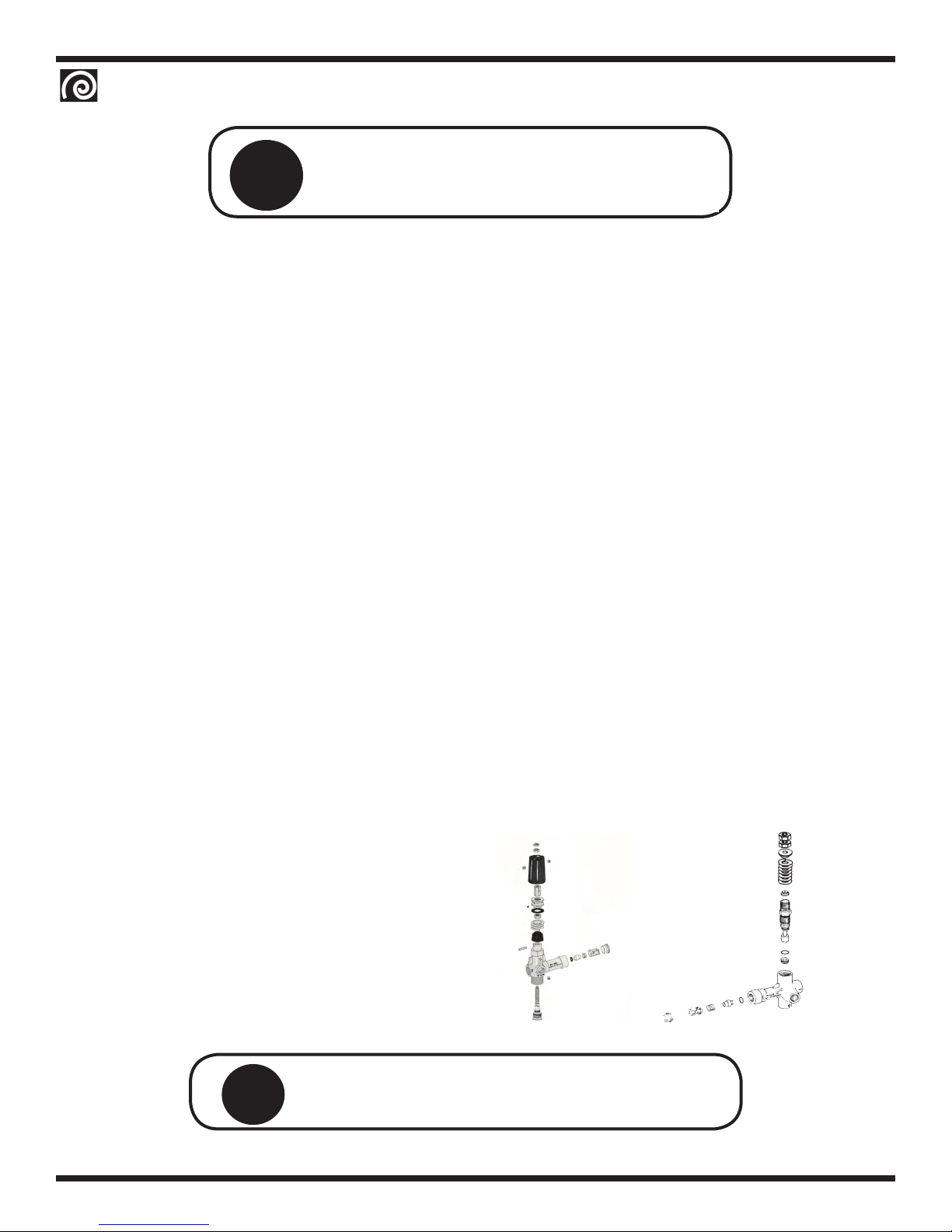
XVNG Belt Drive Pumps
General Pump TC1509S17, TC1809S17, TC91811S17 Triplex Pump
Ref.# Part # Description Qty
1a 220-00105-01 TC1509S17 Triplex Plunger Pump Complete (XV150, XV200) 1
1b 220-00106-01 TC1809S17 Triflex Plunger Pump Complete (XV200, XV300) 1
1c 220-00107-01 TC1811S17 Triplex Plunger Pump Complete (XV500) 1
2a 221-0000XX-X Manifold, Brass Head (TC1509S17 & TC1811S17) 1
2b 221-0000XX-X Manifold, Brass Head (TC1809S17) 1
Pump Repair Kits
221-00021-01 Check Valve Assembly Kit #123 (All TC Pumps) 1 kit
221-00003-01 Oil Seal Kit #83 (All TC Pumps) 1 kit
221-0000X-XX Seals, HP, 15mm Kit #196 (TC1509S17 & TC1811S17) 1 kit
221-0000X-XX Seals, HP, 18mm Kit #197 (TC1809S17) 1 kit
221-0000X-XX Rings, 15mm Kit #198 (TC1509S17 & TC1811S17) 1 kit
221-0000X-XX Rings, 18mm Kit #199 (TC1809S17) 1 kit
221-0000X-XX Seals, LP, 15mm Kit #200 (TC1509S17 & TC1811S17) 1 kit
221-0000X-XX Seals, LP, 18mm Kit #225 (TC1809S17) 1 kit
221-0000X-XX Packing, 15mm Kit #226 (TC1509S17 & TC1811S17) 1 kit
221-0000X-XX Packing, 18mm Kit #227 (TC1809S17) 1 kit
1
2

OperatOr’sManual
RAMTEQ®14275 NORTHWEST FREEWAY HOUSTON, TX 77040 PHONE: 713.983.6000 FAX: 713.983.6405 300-00010-03 8/05
page 8
Dual Lance Wand
Down Stream injection
6
7
8
1
3
4
5
2
Hose, Wand & Gun
Ref.#
Part # Description Qty
1 270-00002-01 Nozzle 4.0 0° 1/4" (XV150) 1
270-00001-01 Nozzle 3.5 0° 1/4" (XV200) 1
270-00006-01 Nozzle 6.0 0° 1/4" (XV200) 1
270-00003-01 Nozzle 4.5 0° 1/4" (XV300) 1
270-00004-01 Nozzle 5.0 0° 1/4" (XV500) 1
270-00002-02 Nozzle 4.0 15° 1/4" (XV150) 1
270-00001-02 Nozzle 3.5 15° 1/4" (XV200) 1
270-00006-02 Nozzle 6.0 15° 1/4" (XV200) 1
270-00003-02 Nozzle 4.5 15° 1/4" (XV300) 1
270-00004-02 Nozzle 5.0 15° 1/4" (XV500) 1
270-00002-03 Nozzle 4.0 25° 1/4" (XV150) 1
270-00001-03 Nozzle 3.5 25° 1/4" (XV200) 1
270-00006-03 Nozzle 6.0 25° 1/4" (XV200) 1
270-00003-03 Nozzle 4.5 25° 1/4" (XV300) 1
270-00004-03 Nozzle 5.0 25° 1/4" (XV500) 1
270-00002-04 Nozzle 4.0 40° 1/4" (XV150) 1
270-00001-04 Nozzle 3.5 40° 1/4" (XV200) 1
270-00006-04 Nozzle 6.0 40° 1/4" (XV200) 1
270-00003-04 Nozzle 4.5 40° 1/4" (XV300) 1
270-00004-04 Nozzle 5.0 40° 1/4" (XV500) 1
2 265-00001-01 36" Wand, Insulated 1
3 275-00001-01 ST1500 Trigger Gun 1
4 552-00004-03 3/8" Quick Connect Plug 1
5 284-00001-01 Hose 3/8" X 50' 3000 PSI Swivel Ends 1
6 554-00006-02 1/4” nptm Quick Connect Socket 1
7 270-00038-01 Nozzle (Low Pressure Soap) #40, 15° 1
8 265-00002-01 Dual Lance Wand 1
Ref.# Part # Description Qty
1 450-00001-01 Rocker Switch 2
2 571-00002-01 Hourmeter (optional) 1
3 305-00040-01 Label, Controls 1
4 573-00001-01 Thermostat Assembly 1
5 180-00289-01 XV Control Box (Not Shown) 1
2
4
3
1
Control Box Area

OperatOr’sManual
RAMTEQ®14275 NORTHWEST FREEWAY HOUSTON, TX 77040 PHONE: 713.983.6000 FAX: 713.983.6405 300-00010-03 8/05
page 9

OperatOr’sManual
RAMTEQ®14275 NORTHWEST FREEWAY HOUSTON, TX 77040 PHONE: 713.983.6000 FAX: 713.983.6405 300-00010-03 8/05
page 10

OperatOr’sManual
RAMTEQ®14275 NORTHWEST FREEWAY HOUSTON, TX 77040 PHONE: 713.983.6000 FAX: 713.983.6405 300-00010-03 8/05
page 11
BLACK
O
RED
W
A2
A1
B
R
W
W B G
R
RED/BLK Stripe
208/230V
460V
BURNER SWPUMP SW
BLU
BLU
BLU
ST 261 UNLOADER SW
PILOT
ALL SINGLE AND THREE
GAS
PHASE UNITS
XV NG/LP
ELECTRICAL SCHEMATIC
VALVE
GAS
(PROVIDED BY CUSTOMER)
110, 208/230 and 460 VOLT
Y
BLU
BLU
HOURMETER
BLU
24 V
Y
1
THERMOSTAT
P
BLU
M1
Y
BLU
BLU
54
23
1
TIMER
BLU
BLK
PRESSURE SW
MOTOR
ELECTRIC
CONTACTOR
T2
T1
T3
3L2
M1
OL
1L1
M1
OL
OL
M1
5L3
BLU
AUX
BLU
MU/PV
MV
PV
24V
PV
MV GND
PV 24V
Y
(GND)
BLU
TH-W
HONEYWELL S8610U
MV
SPARK
LINE POWER INPUT
BLK R R BRN
R
BLK
BLK
BLK
YY
Y
Y
New Wiring Effective 4/26/05
Removed for 1 PH units
Added for 1 PH units
control box
optional
G
XVNG Wiring Diagrams

OperatOr’sManual
RAMTEQ®14275 NORTHWEST FREEWAY HOUSTON, TX 77040 PHONE: 713.983.6000 FAX: 713.983.6405 300-00010-03 8/05
page 12
Low Water Pressure Insufficient water source Check hose size/water source
Old or incorrect nozzle Replace nozzle
Plumbing or hose leak Tighten, repair or replace leak
Obstruction in spray nozzle Clean or replace nozzle
Chemical valve open Close valve or submerge hose
Unloader valve worn Replace unloader
Pump valves dirty or worn Clean or replace packing/valves
No Chemical Flow Detergent valve closed Open detergent valve
Low detergent level Fill detergent container
Chemical screen dirty Clean detergent screen
Pilot will not light No fuel Ensure proper gas flow
Burner will not fire Burner switch turned off Turn burner switch on
Thermostat set too low Reset thermostat
Defective pressure switch Replace pressure switch
Trigger not pulled Burner should fire only when trigger pulled
Gas valve turned off Turn gas valve on
No voltage to valve Check voltage between valves
Pilot orifice plugged Remove orifice & clean
Defective ignition module Check voltage to & through module.
Defective transformer Replace transformer
Defective thermostat Replace thermostat
Faulty rocker switch Replace switch
Igniter not working Test for spark and continuity between
ignition wire and ground
WARNING: High voltage ignitor can cause electrical shock
.
Pilot lights, but burner will not fire
Check for 24v between main valve and pilot valve
If no voltage at the valve, replace module
If voltage, replace valve
Burner fires, but goes out
Check for continuity between ignition cable and ground wire
Assure good ground
Faulty ignition module Replace module
Excess draft Protect from windy conditions
Discharge water temperature Faulty thermostat Replace thermostay
too high Water restriction Clean or replace spray nozzle
Descale coil
Incoming gas pressure too high Check and lower gas pressure
Discharge water temperature not Worn spray nozzle Replace spray nozzle with proper size
reaching maximum temp setting. Gas pressure too low Increase gas pressure
Draft under burner manifold Prevent down draft with installation
ofdraft diverter
Burner continues to fire even Faulty pressure switch Replace pressure switch.
when water not being sprayed Main gas valve stuck open Replace main gas valve.
Pressure Relief Valve Leaks Nozzle is dirty Clean or replace nozzle
Defective relief valve Replace relief valve
Unloader adjusted incorrectly Adjust unloader valve
Restriction on discharge hose Remove nozzle and flush line
Scale restricting flow in coil Clean coil
Pump Motor Not Running Pump motor switch off Turn on pump motor switch
GFCI tripped Reset and test GFCI
No voltage to machine Check power source
Clogged water nozzle Clean water nozzle
Insufficient voltage/amperage Use proper drop cord
Pump Noisy Air in suction line Check inlet water fittings
Pump valves dirty Clean/replace pump valves
Check valve springs worn Replace check valves
Low pump oil Add SEA 30wt. non-detergent
Pump bearings are worn Replace/rebuild pump
Incoming water too hot Reduce temperature/ambient
Water In Oil High humidity environment Change oil frequently
Oil seal worn Check and replace oil seal
Plunger packing worn Check and replace packing
Water Dripping/Pump Plunger packing is worn Install new packing kit
Plunger retainer oil ring worn Replace oil ring
Cracked ceramics Replace ceramics
Oil Dripping Oil seal worn Check and replace oil seals
Cracked manifold Replace manifold
Fluctuating Pressure Unloader not adjusted Adjust to specifications
Valves worn Replace with valve kit
Dirt or blockage in valves Clean or replace valve
Pump sucking air Check water/detergent supply
Worn plunger packing Replace packing kit
Pump Head Overheating Extended period in bypass Pull trigger gun for water flow
problem cause action
Troubleshooting

RAMTEQ
RAMTEQ®14275 NORTHWEST FREEWAY HOUSTON, TX 77040 PHONE: 713.983.6000 FAX: 713.983.6405 300-00001-01 1/13
WARRANTY
Limited One Year
Ramteq Incorporated ("RAMTEQ") warrants that the Product you have purchased from RAMTEQ or from an
Authorized RAMTEQ Reseller is free from defects in materials or workmanship under normal use for a period of one
(1) year from the date of purchase. This warranty extends only to you, the original Purchaser. It is not transfer-
able to anyone who subsequently purchases the Products from you. This warranty specifically excludes expendable
items, including but not limited to hoses, seals, nozzles and gunjets. RAMTEQ manufacturers warrant certain com-
ponents of the Products for periods greater than one (1) year. MOTORS, GENERATORS, PUMPS, COILS, BURNERS
AND ENGINES ARE WARRANTED BY THEIR RESPECTIVE MANUFACTURERS, AND SERVICED THROUGH THESE
MANUFACTURERS' LOCAL AUTHORIZED SERVICE CENTERS. Specific warranty details can be found on the indi-
vidual manufacturers website. RAMTEQ CANNOT PROVIDE WARRANTY ON THESE ITEMS.
During the warranty period, RAMTEQ will repair or replace defective parts, at the option of RAMTEQ.
This limited warranty does not extend to any Product not purchased from RAMTEQ or from an Authorized RAMTEQ
Reseller. This limited warranty also does not extend to any Product that has been damaged or rendered defective (a)
as a result of accident, misuse or abuse; (b) by operation outside the specifications in the intended applications; (c) by
the use of parts not sold or manufactured by RAMTEQ; (d) by the modification of the Product.
Warranty Disclaimer
EXCEPT AS EXPRESSLY SET FORTH IN THIS WARRANTY, RAMTEQ MAKES NO OTHER WARRANTIES, EXPRESS
OR IMPLIED, INCLUDING ANY IMPLIED WARRANTIES OF MERCHANTABILITY AND FITNESS FOR A PARTICULAR
PURPOSE. RAMTEQ EXPRESSLY DISCLAIMS ALL AND ANY WARRANTIES NOT STATED IN THIS LIMITED
WARRANTY. ANY IMPLIED WARRANTIES THAT MAY HAVE BEEN IMPOSED BY LAW ARE LIMITED TO THE TERMS
OF THIS EXPRESS LIMITED WARRANTY.
Limitation of Remedy
RAMTEQ IS NOT LIABLE FOR ANY DAMAGES CAUSED BY THE PRODUCT OR FAILURE OF THE PRODUCT TO
PERFORM, INCLUDING INCIDENTAL AND CONSEQUENTIAL DAMAGES. THIS LIMITATION APPLIES WHETHER
DAMAGES ARE SOUGHT, OR A CLAIM MADE, AS A CONTRACT CLAIM, AS A TORT CLAIM, OR ANY OTHER
CLAIM.
THIS LIMITATION OF LIABILITY, HOWEVER, WILL NOT APPLY FOR PERSONAL INJURY.
U.S.A. State Laws
Some states do not allow limitation on how long an implied warranty lasts. In such states, the limitations or
exclusions of this Limited Warranty may not apply to you.
Some states do not allow the exclusion or limitation in incidental or consequential damages for consumer products. In
such states, the exclusion may not apply to you. This limited warranty gives you specific legal rights. You may also
have other rights that may vary from state to state. You are advised to consult applicable state laws for a full
determination of your rights.
How to Obtain Warranty Service
TO OBTAIN WARRANTY SERVICE YOU MUST CONTACT RAMTEQ or an AUTHORIZED RAMTEQ RESELLER.

Ramteq
Ramteq Pressure Washers 14275 NORTHWEST FREEWAY HOUSTON, TX 77040 PHONE: 713.983.6000 FAX: 713.983.6405 1/13
Click on pictures to open manufacturers website.
Manufacturers Warranty Period
5 years
5 years
3 years
3 years
3 years
18 months
18/36 months 1 year
3 years
This manual suits for next models
1
Table of contents
Other Ramteq Pressure Washer manuals
Popular Pressure Washer manuals by other brands

Nilfisk-ALTO
Nilfisk-ALTO NEPTUNE 7 FA operating instructions

Kärcher
Kärcher ProHD G 400 manual

Generac Power Systems
Generac Power Systems 4040 PRO GAS PW 49ST Operator's manual

IPC
IPC PW-H25 Universe instruction manual

Husky
Husky HU80931 Operator's manual

Generac Portable Products
Generac Portable Products 1676-1 owner's manual