Manual-4
©Rane Corporation 10802 47th Ave. W., Mukilteo WA 98275-5098 TEL 425-355-6000 FAX 425-347-7757 WEB www.rane.com
106328
OPERATION
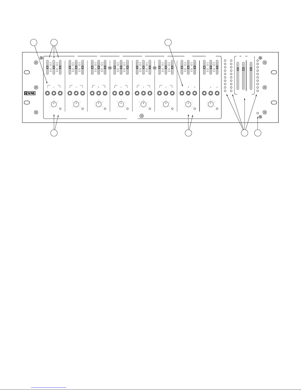
MONO MICROPHONE/LINE LEVEL INPUTS 1-6
e rear-panel MIC/LINE INPUT TRIM adjusts the input
gain before the front panel LEVEL controls. When an Input’s
LINE/MIC button is in the “out” position (Mic Level), the gain
range is 12 to 60 dB. When an Input’s LINE/MIC button is in
the “in” position (Line Level), the gain range is -4 to 12 dB.
First, input some “loud” source material (like a pop metal
or disco CD, give a kid a mic, etc). en, using a screwdriver,
adjust the TRIM for each Input so that the front panel OL LED
illuminates only occasionally during extreme peaks. e 3-band
Equalizer settings will influence this, so keep on eye on the OL
when making EQ adjustments.
Push the PHANTOM POWER button (when needed) for
each pair of Inputs. If the LINE/MIC button is engaged (Line
Level), Phantom Power is automatically defeated for that Input.
e PHANTOM POWER button activates 12 volts which is
sufficient power for all but the most esoteric condenser mics. If
in doubt, check the manufacturer’s microphone specs.
Assign each Input to the desired Output by pushing any
combination of the A, B or AUX ASSIGN buttons.
e LEVEL of each Input can now be adjusted as needed
without danger of blowing your speakers, or scaring the neigh-
bors, whichever you deem worse.
STEREO LINE LEVEL INPUTS 7/8 and 9/10
When a stereo source (CD, DVD, Satellite radio, etc.) is con-
nected to Inputs 7/8 (or 9/10), the routing is as follows:
When the ASSIGN button is engaged and the MONO but-
ton is not engaged, INPUT 7 (or 9) is routed to the A Output,
while INPUT 8 (or 10) is routed to the B Output.
When both the ASSIGN and MONO buttons are engaged, a
mono mix of INPUTs 7/8 (or 9/10) will be routed to both the A
and B Outputs.
e AUX ASSIGN button is always a mono mix of the stereo
channel.
OUTPUT LEVELS
After all of the Mic/Line and Stereo Input Levels have been
adjusted and routed, adjust the OUTPUT faders so the Meters
peak average around 0 to +2.
SECURITY COVER
e MLM 103 comes with an installed security cover for the
EQ and ASSIGN switches only, leaving the LEVEL controls and
metering exposed for regular operation. is feature is valuable
when you want to protect those painstaking settings from casual
operators.
e cover is removed and replaced by two screws. If the se-
curity cover will not be used, remove the chrome standoffs from
the front panel and replace with the black screws in these same
locations.
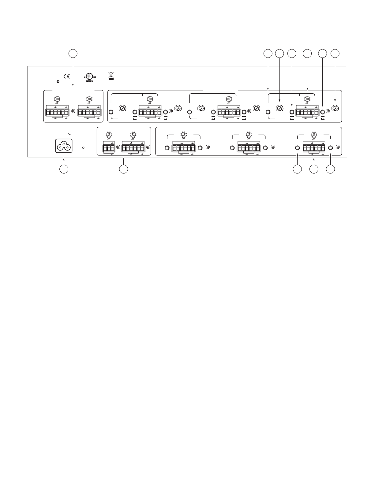
CONNECTION
INPUTS
e MLM 103 has ten balanced Euroblock Inputs. Use only
shielded cable, #12 to #24 AWG. For best noise rejection use
two-conductor-plus-shielded wire, even for unbalanced opera-
tion. Connect the non-inverting (positive) audio lines to the “+”
terminals, and the inverting (negative) lines to the “–” terminals.
Connect the shields to the “ground” terminals.
For those installations where the MLM 103’s internal shield-
to-chassis connection causes interference, connect the shields
directly to chassis PEM nuts directly above each pair of Eurob-
lock connectors. Be sure to bite through the paint with the star
washer and keep the shields wrapped around the audio conduc-
tors as much as possible. For the “theoretical” best ElectroMag-
netic Interference (EMI) immunity, connect the shields at both
ends of the cables. (For more information on connections, see
the RaneNote, “Sound System Interconnection” later in this
manual or on Rane’s website.)
MONO INPUTS 1-6 can accept either mic or line level
sources. When connecting line level signals, push the rear panel
button in for LINE. For mic signals, be sure the button is in the
MIC (out) position.
STEREO INPUTS 7/8 and 9/10 accept line level stereo and
mono sources.
OUTPUTS
e MLM 103’s OUTPUTS (and DIRECT OUTPUTS) are
balanced. e same wiring conventions as the Euroblock Inputs
apply.