Rane TTM 56 User manual

TTM 56
PERFORMANCE MIXER

IMPORTANT SAFETY INSTRUCTIONS
For the continued safety of yourself and others we recommend that you read the following
safety and installation instructions. Keep this document in a safe location for future reference.
Please heed all warnings and follow all instructions.
Do not use this equipment in a location where it might become wet. Clean only with a damp
cloth.
is equipment may be installed in an industry standard equipment rack. We recommend that
all mounting holes be used, providing the best physical support. e equipment may be used as
a table top device, although stacking of the equipment is dangerous and not recommended.
Do not directly block any of the ventilation openings. If rackmounting, please provide adequate
ventilation. Equipment may be located directly above or below this unit, but note that some
equipment (like large power amplifiers) may cause an unacceptable amount of hum or may
generate too much heat and degrade the performance of this equipment.
Protect the power cord and plug from damage caused by being walked on or pinched. Protect
the line cord, where it exits the unit, from excessive strain. Only use attachments and acces-
sories specified by Rane.
Unplug this equipment during lightning storms or when unused for long periods of time.
Do not defeat the safety purpose of the grounding type plug. is plug has two blades and a
third grounding prong. e third prong is provided for your safety. If the provided plug does
not fit into your outlet, consult an electrician for replacement of the obsolete outlet.
Refer all servicing to qualified service personnel. Servicing is required when the apparatus has
been damaged in any way, such as power supply cord or plug damage, spilled liquid, fallen
objects into an opened chassis, exposure to rain or moisture, a dropped unit, or abnormal
operation.
108246

Manual-1
TTM 56
PERFORMANCE MIXER
OPERATORS MANUAL
Quick Start
Congratulations! You are the proud owner of an exceptional
performance instrument. Experienced turntablists will find the
TTM 56 comfortable and familiar. e TTM 56 has many unique
features which are mastered quicker if you read the manual. Right!
We know you can’t resist jumping right in, but please read at least
this portion of the manual. It will help you get a good start.
About the faders: e program faders and crossfader are magnetic,
non-contact faders. is means No travel noise – No bleed – Ever!
e electrical performance of the faders is unaffected by use. Old
habits are hard to break, but you really don’t have to mess with
these faders. e magnetic faders in this mixer are very different
from what you are used to. Be sure and read the Qand Asection
on page Manual-8.
Special Features:
• Program fader MODE switches allow selecting two sets of
curves:
MODE 1 gives the familiar stereo fader response.
MODE 2 gives a left/right pan effect.
• Both curves allow continuous adjustment of CONTOUR, giv-
ing smooth blend or fast cut.
• e CHANNEL REVERSE switch allows the left-hand or
right-hand fader to control PGM 1 or PGM 2.
WEAR PARTS: is product contains the following wear parts subject to the ninety (90) day warranty period described on page
Warranty-1: ST 2 Phono/Line Switch Assembly (2).
• e CROSSFADER MODE switch allows selecting two sets of curves:
MODE 1 gives the familiar PGM 1 to PGM 2 cross-fade response.
MODE 2 gives a center cut response (PGM 1 and PGM 2 are off in the center).
• Independent CONTOUR controls for each side of the crossfader allow cut on one side and blending on the other (or any combination).
• Auxiliary Inputs and Outputs, with independent level controls, give session mixing ability.
AUX Inputs may be used for a drum machine, tape, etc.
AUX Input is after the crossfader and after the effects loop.
AUX Outputs may be used for recording, booth monitoring, or a second zone.
AUX Output is the same as the Master Mix.
• FlexFX™allow assignment of PGM 1, PGM 2 or both to the effects loop. e effects loop is post-fader. You get great results when us-
ing the program faders or crossfader with reverb or other delay effects. WET/DRY pan lets you control how much effect is in the mix.
• ree-band Accelerated-Slope™ EQ allows full cut of each band. e EQ engage switch lets you A/B compare or quickly transform the
EQ effect.
• Two 10-segment meters provide dual-mono-Cue or stereo-Master operation.
• Yes, we included a power switch on the rear.
e flexibility of the TTM 56 faders can result in some initial confusion. We highly recommend trying one thing at a time to avoid
this. Make sure the CHANNEL REVERSE switch is off. Start by changing the Mode and Contour of each fader, one at a time. See the dia-
grams on pages Manual-6-7 to understand the fader responses under different settings. Once you understand the controls, start creating!
MIC
LEVEL
HIGH
LOW
HIGH GAIN GAIN HIGH
MID
EQ EQ
MID AUX OUT
LOW
FlexFX FlexFX
LOW PHONES LEVEL
PGM 2PGM 1
MASTEROL
100
+12-12
+12-12
+6OFF
+6OFF
+6OFF
+6OFF
+6OFF
+6OFF
100
64
2 8
64
2 8
100
64
2 8
100
64
2 8
100
64
2 8
100
64
2 8
AUX IN
+10
+7
+4
+2
0
-4
-2
-7
-10
-20
100
64
2 8
PERFORMANCE MIXER
FAST
SLOW
TTM 56
L
REVERSE
CONTOUR
REVERSE
MODE 1
MODE 2
CONTOUR
MODE 1
MODE 2
CHANNEL REVERSE
TRANSFORM TRANSFORM
STEREO HOUSE
MONO PGM1 / PGM2
A B
PAN RDRY WET LPAN MASTER / CUE
R
PGM 1 CUE PGM 2
REVERSE MODE 1 MODE 2
FAST
SLOW

Manual-2
Rear Panel Hook-up
Inputs
PGM 1 and PGM 2 each have stereo PHONO and stereo LINE inputs.
PHONO 1 and PHONO 2 inputs are RIAA compensated inputs, for turntables only!
PHONO GND terminals provide independent ground connect points for turntables. It is very important that each turntable have a
very good ground connection to one of these terminals. e thumbscrews will come off if they are over-rotated, so be careful not
to spin them off and lose them.
LINE 1 and LINE 2 inputs are unbalanced line-level inputs with a sensitivity of -10 dBV (max gain).
AUX INPUT may be used with a drum machine, groovebox, sampler, or another mixer’s output for session mix. is Input is mixed
after the Crossfader and Effects loop.
MIC INPUT is a balanced input specifically designed for a dynamic microphone.
Power
POWER connector. is is not a telephone jack! Connect only the Rane RS 1 power supply included with your TTM 56.
e POWER switch is located just above the power connector. You know what to do with this one, but leave it off until everything is
connected.
Effects Loops
MIC EFFECTS insert jack is unbalanced. It is wired for TRS, Tip=Send, Ring=Return. is is an independent Effects Loop for the
Mic. ere is no engage switch, so the Mic signal is always processed when you have an effects box connected. If you are connect-
ing to an effects processor with a Send/Return jack, a single TRS cable will work. If your effects processor has separate Send and
Receive jacks, you need a “Y” cable. You can buy a Send/Return cable from your local music store, or you can make one of your
own, as shown below.
FlexFX EFFECTS jacks are unbalanced mono ¼" TS (Tip/Sleeve). is stereo loop is used for output to (send) and input from (re-
turn) an effects processor. e SEND jacks provide the output to your effects processor. e RETURN jacks provide input for the
signal returning from your effects processor. To use with effects insert devices with a single TRS, tip=send, ring=return jack, you
need a “Y” cable, as shown below.
1-CONDUCTOR SHIELDED CABLE
T = SEND
R = RETURN
S = SHIELD
+ + SEND
RETURN
+ +
SHIELD SHIELD
SHIELD
Send/Return Cable Wiring
TTM 56
FlexFX
MASTER OUT
PHONO
GROUND
EFFECTS
PGM 2AUX PGM 1
MIC
UNBALANCED
BALANCED
MADE IN U.S.A.
RANE CORP.
U.S. PATENT
6,813,361
R
L
R
L
R
L
L
R
L
OUT IN
RETURN
TIP = SEND
RING = RETURN
R
BAL INPUT
LINE 2
SEND
PHONO 2 PHONO 1LINE 1
ACN 001 345 482
CLASS 2 EQUIPMENT
750mA
POWER

Manual-3
Outputs
AUX OUT may be used for recording, booth monitoring, a second zone, or for connecting to another mixer for session mix. AUX
OUT is the same as the Master Mix with independent Level control.
MASTER OUT includes two sets of stereo outputs: e ¼" TRS jacks provide high current balanced (Tip-Ring-Sleeve) output.
Use the balanced output whenever driving equipment with a balanced input, or when running distances greater than 10 feet (3
meters). Due to the high drive capability and low impedance, never use a mono ¼" Tip/Sleeve (no ring) plug in this jack. Use the
RCA unbalanced outputs for shorter runs connecting to unbalanced devices. See the RaneNote “Sound System Interconnection”
if you need to convert between balanced and unbalanced or run long distances.
Mic Section
MIC LEVEL sets the gain of the
Mic Input. e range of opera-
tion is OFF to +50 dB. ere
is no engage switch, so set the
MIC LEVEL to zero (0) when
not in use.
e OL indicator lights 6 dB before
clipping. Adjust MIC LEVEL
so the OL indicator flashes only
when you shout into the mic.
MIC HIGH and LOW tone con-
trols provide as much as 12 dB
of boost or 12 dB of cut. ese
controls have no effect when the
controls are set to their center
detent (12 o'clock).
Program and Aux Input Section
PGM 1 inputs are sent to the left side of the crossfader. (with the REVERSE switch out)
PGM 2 inputs are sent to the right side of the crossfader. (with the REVERSE switch out)
AUX INPUT adds another line-level input to the mix. is input comes in after the crossfader and FlexFX Loop.
GAIN controls adjust the signal level before it gets to the Faders. Set the GAIN controls to indicate an average signal level of +4
on the meter with the program faders set to maximum. Don't use the GAIN controls to set the output level...use the MASTER
LEVEL control to set the output level. is is a very simple thing, yet makes a huge difference in the performance of your mixer.
EQ switches engage the 3-band tone controls. EQ switches may be used in conjunction with the Hi, Mid and Low controls as “kill”
switches. Set the rotary controls and flip the switch.
HIGH tone controls affect frequencies above 4 kHz. e range of control is +6 dB to OFF (full kill). e center detent position leaves
this filter inactive. is filter is just above the vocal range, and can make small tonal changes, or eliminate high frequency signals.
MID tone controls affect frequencies from 300 Hz to 4 kHz (vocal midrange). e range of control is +6 dB to OFF (full kill). e
center detent position leaves this filter inactive. Use for small tonal changes or to cut midrange signals.
LOW tone controls affect frequencies below 300 Hz. e range is +6 dB to OFF (full kill). e center detent position leaves the filter
inactive. ese filters influence signals below the vocal range. Use to adjust or eliminate bass beats.
PAN controls adjust the Left and Right balance of PGM 1 and PGM 2. Don't use these excessively for left/right pan effect, they are
not as durable as the Faders. For left/right pan effect, use the program faders in Mode 2.
MIC
LEVEL
HIGH
LOW
HIGH GAIN GAIN HIGH
MID
EQ EQ
MID AUX OUT
LOW
FlexFX FlexFX
LOW PHONES LEVEL
PGM 2PGM 1
MASTEROL
100
+12-12
+12-12
+6OFF
+6OFF
+6OFF
+6OFF
+6OFF
+6OFF
100
64
2 8
64
2 8
100
64
2 8
100
64
2 8
100
64
2 8
100
64
2 8
AUX IN
+10
+7
+4
+2
0
-4
-2
-7
-10
-20
100
64
2 8
PERFORMANCE MIXER
FAST
SLOW
TTM 56
L
REVERSE
CONTOUR
REVERSE
MODE 1
MODE 2
CONTOUR
MODE 1
MODE 2
CHANNEL REVERSE
TRANSFORM TRANSFORM
STEREO HOUSE
MONO PGM1 / PGM2
A B
PAN RDRY WET LPAN MASTER / CUE
R
PGM 1 CUE PGM 2
REVERSE MODE 1 MODE 2
FAST
SLOW

Manual-4
MIC
LEVEL
HIGH
LOW
HIGH GAIN GAIN HIGH
MID
EQ EQ
MID AUX OUT
LOW
FlexFX FlexFX
LOW PHONES LEVEL
PGM 2PGM 1
MASTEROL
100
+12-12
+12-12
+6OFF
+6OFF
+6OFF
+6OFF
+6OFF
+6OFF
100
64
2 8
64
2 8
100
64
2 8
100
64
2 8
100
64
2 8
100
64
2 8
AUX IN
+10
+7
+4
+2
0
-4
-2
-7
-10
-20
100
64
2 8
PERFORMANCE MIXER
FAST
SLOW
TTM 56
L
REVERSE
CONTOUR
REVERSE
MODE 1
MODE 2
CONTOUR
MODE 1
MODE 2
CHANNEL REVERSE
TRANSFORM TRANSFORM
STEREO HOUSE
MONO PGM1 / PGM2
A B
PAN
RDRY WET L
PAN MASTER / CUE
R
PGM 1
CUE
PGM 2
REVERSE MODE 1 MODE 2
FAST
SLOW
CONTOUR A CROSSFADER CONTOUR B HEADPHONES
MODEREVERSE
PWR
CHANNEL REVERSE switch allows
the left-hand or right-hand Fader
to alternately control PGM 1 or
PGM 2. (Don't confuse with the
program fader REVERSE switch,
see below.)
TRANSFORM switches provide two
functions:
• PHONO / LINE source selection
for PGM 1 and 2.
• Quick cut between the used and
unused input. e switches are
easily field replaceable and may be
rotated in 45° increments. See page
Manual-10 for instructions.
Faders
e program faders and crossfader are magnetic, non-contact
faders. is means No travel noise or bleed ! e electrical
performance of the faders is unaffected by use. e program
faders and crossfader each have their own CONTOUR,
REVERSE (hamster) and MODE controls. Magnetic
faders are very different from what you are used to. Read
Maintaining Magnetic Faders on pages Manual 8-9.
Program fader MODE switches: allow selecting two sets of
curves. MODE 1 gives the familiar stereo fader response.
MODE 2 gives left/right pan effect.
Program fader CONTOUR controls: allow smooth, continu-
ous adjustment of contour for both MODE 1 and MODE
2. e range of control is from SLOW blend to FAST cut.
Program fader REVERSE switches change the direction of
the program faders. When the reverse switch is engaged, up
is down and down is up (hamster).
CROSSFADER MODE switch allows selecting two sets of
crossfader curves. MODE 1 gives the familiar PGM 1 /
PGM 2 crossfade response. MODE 2 gives a center cut
response (PGM 1 and PGM 2 off in the center).
CROSSFADER CONTOUR A & B provide independent
control for each side of the crossfader. is allows a fast cut
on one side and slow blending on the other (or any combi-
nation you choose).
Meters
Meters provide switchable true stereo Master Mix or dual-
mono PGM1 / PGM2 indication of Pre-Program fader
signal levels. Ten-segment resolution is provided with a one
second, peak hold. Use the meter to set the GAIN controls.
With the program fader set to maximum, the input GAIN
should be set to indicate an average level of about +4 dB.

Manual-5
FlexFX Loop
FlexFX switches send PGM 1, PGM 2 or both to the stereo effects loop. e effects loop is post-fader and post-crossfader. You get
great results when using the program faders or crossfader with reverb or other delay effects. e effects loop provides separate
stereo send and return jacks. e green indicators light when FlexFX is engaged.
WET/DRY pan control lets you set the amount of effect in the mix. DRY equals no effect, WET gives maximum effect.
Output Section
MASTER control sets the level for both the unbalanced and balanced Master Outputs.
AUX OUTPUT control sets the level of the Auxiliary Outputs.
Headphone Cueing
e headphone amp in the TTM 56 has a high power output (unlike most you have used before). ere
are notable differences…
• e headphone output of the TTM 56 delivers very high volume to your headphones.
• To avoid pain, never put headphones on your head before plugging them in.
• Always start with the PHONES LEVEL turned down, and then turn it up to the desired level.
• Because of the high current and low output impedance, never short one side to ground, or short left
and right together as is possible with mono cup headphones.
• Low power headphone stages typically use large resistors on their outputs, which allow shorting, but
prevent high power. e TTM 56 gives you high power, but does not allow shorting.
MASTER / CUE switch is used to select the headphone monitor source:
• Use MASTER (out) to rehearse your performance. is signal is the same as the MASTER OUT,
but is not affected by the MASTER LEVEL control.
• Use CUE (in) to monitor the Program Input signal before fading in. is signal is not affected by
the Program Faders or Crossfader. Because the Effects Loop is after the Fader, you will not hear effects
in the Cue.
CUE slider allows you to PAN between PGM 1 and PGM 2 in the headphones when the MASTER / CUE switch is depressed. When
the switch is released, this control has no effect.
PHONES LEVEL control sets the output level of the headphone amplifier.
CONTOUR A CROSSFADER CONTOUR B HEADPHONES
MODEREVERSE
PWR
MIC
LEVEL
HIGH
LOW
HIGH GAIN GAIN HIGH
MID
EQ EQ
MID AUX OUT
LOW
FlexFX FlexFX
LOW PHONES LEVEL
PGM 2PGM 1
MASTEROL
100
+12-12
+12-12
+6OFF
+6OFF
+6OFF
+6OFF
+6OFF
+6OFF
100
64
2 8
64
2 8
100
64
2 8
100
64
2 8
100
64
2 8
100
64
2 8
AUX IN
+10
+7
+4
+2
0
-4
-2
-7
-10
-20
100
64
2 8
PERFORMANCE MIXER
FAST
SLOW
TTM 56
L
REVERSE
CONTOUR
REVERSE
MODE 1
MODE 2
CONTOUR
MODE 1
MODE 2
CHANNEL REVERSE
TRANSFORM TRANSFORM
STEREO HOUSE
MONO PGM1 / PGM2
A B
PAN RDRY WET LPAN MASTER / CUE
R
PGM 1 CUE PGM 2
REVERSE MODE 1 MODE 2
FAST
SLOW

Manual-6
FULL ON
OFF
FULL ON
OFF
FULL ON
OFF
FULL ON
OFF
LEFT
RIGHT
LEFT
RIGHT
Channel Fader Response
Channel Fader Response showing eect of Reverse, Mode 1, Mode 2, and Contour controls.

Manual-7
Crossfader Response showing eect of Reverse, Mode 1, Mode 2, and Contour controls.
Crossfader Response

Manual-8
Maintaining Magnetic Faders
ere are no electrical contacts to clean!
e faders in the TTM 56 are designed with materials highly
resistant to corrosion and most chemicals. While the faders will
handle millions of operations, they may become dirty over time.
Bad things may be spilled or sprayed into the faders. In either case,
the faders are not damaged and the sound quality is unaffected.
Cleaning is only required to maintain the feel of the faders.
e faders are self-lubricating and with normal use, should
not require additional lubrication. If you wish, you can use a light
silicone lubricant rated for use with electrical parts. is will help
maintain the feel. We recommend Caig DeoxIT FaderLube
F100
spray lubricant.
Order DeoxIT® F100 from CAIG Laboratories, Inc.
12200 atcher Ct.
Poway, CA 92064
Phone 858-486-8388
Fax 858-486-8398
Web www.caig.com
Never use a heavy lubricant or grease. Doing so will not
damage the faders, but can undo the feel. If grease was used, it may
be removed by following the cleaning instructions. Light lubrica-
tion is possible with the Lexan plate on. A couple of drops or a
short spray are all that is required. Make sure the products you use
are suitable for use with electrical parts that contain plastic.
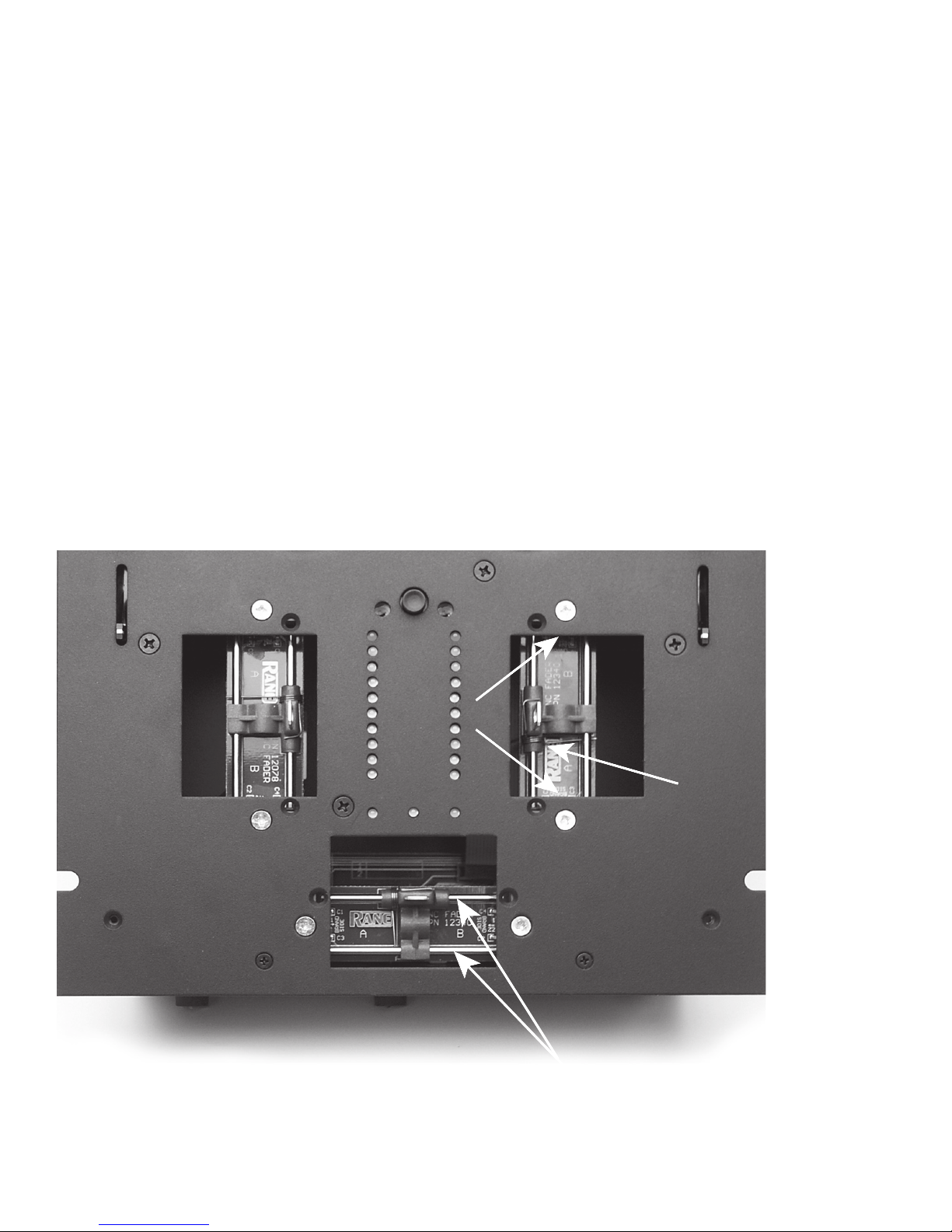
Sensors
Rails
Transform
Switch
Torsion
Spring
Magnetic Slider Rail Cleaning
a. Move the carrier all the way to one side.
b. Use a soft lint-free cloth to wipe off rails.
c. Add a drop of silicone lubricant (or quick spray from aerosol) to the center of each rail.
d. Move the carrier back and forth to distribute lubricant.
e. Do not bend torsion spring or touch sensors.
Magnetic Fader Q and A
Q: Will I damage the faders if I spray them with bad stuff or spill
bad things in them?
A: No. e faders in the TTM 56 are designed with materials high-
ly resistant to corrosion and most chemicals. ere are no electri-
cal contacts to clean or damage. While bad things may change the
feel of the faders, bad things will not affect the sound. To clean
faders that have had a bad thing put in them, follow the simple
instructions on page Manual-8.
Q: Can I install magnetic faders in any other mixer?
A: Sorry. e connectors may be similar, but the circuits are very
different. Connecting the faders to anything other than the in-
tended cable in the TTM 56 could permanently damage them.
Q: Can I install other faders in my TTM 56?
A: No. e cable connections are specially designed for Rane mag-
netic faders.
Q: Can I install a different magnetic fader in my mixer or swap
the position of my faders?
A: No. In order to achieve the highest possible accuracy, each
magnetic fader is factory calibrated for the location in which it
was shipped. For information about replacement or calibration,
contact Rane Customer Service. If you remove the faders for
cleaning, make sure you mark them. is helps you to put them
back in the same location.

Manual-9
Torsion spring
Sensors
Remove ribbon
Remove
#4 screw
Remove
#4 screw
Mark location before
disconnecting ribbon:
PGM 1
PGM 2
XFADER
For more effective cleaning and lubrication, follow the directions outlined below:
1. Required Tool: #1 Philips screwdriver
2. Disconnect the power.
3. Remove knobs from controls covered by the Lexan faceplate.
4. Remove the four, 4-40 screws attaching the Lexan faceplate.
5. Remove the Lexan faceplate. See the picture and instructions below. e rails of the fader are now accessible for normal cleaning and
lubrication.
6. Remove fader from mixer if more thorough cleaning is required.
7. NOTE: Do not disturb the position of the small sensors at each end of the Fader. If you do, make sure the parts are standing straight before
reinstalling.
8. NOTE: In order to achieve the highest possible accuracy, each magnetic fader is factory calibrated for the location in which it was
shipped. If you remove the faders for cleaning, make sure you mark them. is helps you to put them back in the correct location.
9. Remove the fader by removing the two #4 screws securing it. en disconnect the ribbon cable.
10. Sugary liquids spilled into a fader may be removed by thoroughly rinsing the part in hot water. Make sure the part is clean and dry
before lubricating or reinstalling.
11. Removal of grease or other stubborn debris may require alcohol or contact cleaner. Make sure the part is clean and dry before lubricat-
ing or reinstalling.
12. To reassemble, reverse the disassembly procedure.
13. Problems? Contact Rane Corporation customer service at 425-355-6000.

Manual-10
©Rane Corporation 10802 47th Ave. W., Mukilteo WA 98275-5098 USA TEL 425-355-6000 FAX 425-347-7757 WEB www.rane.com
106266
Rotating or Replacing Transform (Phono/Line) Switches (model ST 2)
1. Required tool: #1 Philips screwdriver
2. Disconnect the power.
3. Remove knobs from controls covered by the Lexan faceplate.
4. Remove the four 4-40 screws attaching the Lexan faceplate.
5. Remove the two 4-40 switch mounting plate screws.
6. If rotating controls only, go to step 10.
7. Remove the two 2.5 mm screws holding the switch to the plate.
8. Remove the ribbon cable from the switch.
9. Attach the ribbon cable to the new ST 2 switch.
10. Reattach the switch to the mounting plate.
11. Rotate the switch to the desired location.
12. Reinstall 4-40 screws holding the switch mounting plate.
13. Reinstall the decor faceplate and re-attach control knobs.
Sensors
Rails
Transform
Switch
Torsion
Spring
Important Note
CHASSIS GROUNDING
If your system exhibits excessive hum or buzzing, there is an incompatibility in the grounding configuration between units some-
where. Here are some things to try:
1. Check that the turntable grounding wires are connected to the PHONO GND posts.
2. Try combinations of lifting grounds on units that are supplied with ground lift switches or links.
3. If your equipment is in a rack, verify that all chassis are tied to a good earth ground, either through the line cord grounding pin or the
rack screws to another grounded chassis, or tied to the ground screw located next to the POWER switch.
4. is unit’s outboard power supply does not ground the chassis through the line cord. Make sure that this unit is grounded either to
another chassis which is earth grounded, or directly to the grounding screw on an AC outlet cover by means of a wire connected to a
screw on the chassis with a star washer to guarantee proper contact.
Please refer to the RaneNote, “Sound System Interconnection” (supplied with this manual and available on our website) for further
information on system grounding.
Other manuals for TTM 56
2
Table of contents
Other Rane Mixer manuals
Popular Mixer manuals by other brands

Varimixer
Varimixer V20K Operating instructions and spare parts

Intellijel
Intellijel Quadratt 1U manual

Wharfedale Pro
Wharfedale Pro Connect Series Operating manual and user guide

Mira
Mira Element Thermostatic Mixer Installation and user guide

B+BTec
B+BTec Diamond3 AutoMixer Premium operating manual

MBW
MBW MM60 Operator's safety and service manual