Raritan STCFS User manual

Installation and Maintenance Instructions
Part# STCFS
SMART TOILET CONTROL
WITH FlushSense®
FlushSense® Control:
Consists of a controller, panel switch and 7’ of
cable, designed to automatically start a ushing
cycle if a hand is within 2” from switch.
Flush timing of initial ll , discharge and nal
ll are factory programmed. Optional multi-
function panel is required to re-program
1
THE FOLLOWING ARE CAUTIONARY STATEMENTS THAT MUST BE READ AND
FOLLOWED DURING BOTH INSTALLATION AND OPERATION.
WARNING: Raritan Engineering Company, Inc. Recommends that a qualied person or electrician install
this product. Equipment damage, injury to personnel or death could result from improper instal-
lation. Raritan Engineering Company, Inc. accepts no responsibility or liability for damage to
equipment, injury or death to personnel that may result from improper installation or operation
of this product.
WARNING: HAZARD OF SHOCK OR FIRE
Always use recommended fuse, circuit breaker and wire size.
Motors used with this product are “Ignition Protected”. They are not however, explosion-
proof as dened in 46CFR 110.15-65(e), Subchapter J-Electrical Engineering.
DO NOT run continuously for more than 30 seconds.
Raritan’s FlushSense® control is designed to automatically activate a ush cycle without touching
the control. Simply waving your hand within 2” of the sensor will begin a sequential ush cycle that
oers guests a simple and sanitary solution to ushing the toilet.
L492 0412vkm

INSTALLATION\OPERATION
2
Mounting control Panel:
FlushSense panel:
Location:
FlushSense will activate if any object is
within 2” of the switch. To avoid any nuisance
activation, switch should be located such that
normal occupying of the bathroom or seating
on the toilet does not activate switch. Avoid
locations where switch will be exposed to direct
light source such as sunlight or tungsten lamp.
1. Cut out a hole per Fig. 2, mark mounting
holes using base plate as guide.
2. Route wire/cable to the toilet and control.
3. Secure control using mounting screws
Smart Toilet Control Box;
1. Locate box near toilet in a dry and accessible
area
2. Using two screws fasten the control to wall
with connectors at the bottom.
3. Using one of the wiring diagram route all
wires.
Fig.1
OPERATION
Moving your hand in front of the switch within
2 inches will activate a ush cycle. The ush
cycle consists of a cycling between bringing in
water and running the macerator for three cycles.
This allows for an ecient ush with less water
usage.
DO NOT use any chemical to clean lenses on the
sensor, use only soap and water.
Fig.2
Switch Mounting
L492 0412vkm

3
Pressurized Freshwater Model - Recommended Wire and Fuse/Circuit Breaker Size
Sea Water Model - Recommended Wire and Fuse/Circuit Breaker Size
Units
Voltage
Circuit
Breaker/
fuse size
(amps)
Remote
Pump and
lower base
Amp. draw
Remote
Pump
only
Amp. draw
15
feet
20
feet 30
feet 40
feet 50
feet
12 VDC 25 23 10 10
AWG
8
AWG
6
AWG
6
AWG
4
AWG
24 VDC 15 12.5 514
AWG
14
AWG
12
AWG
10
AWG
10
AWG
Units
Voltage
Circuit
Breaker/fuse
size (amps)
Amp.
draw
10
feet 15
feet 20 feet 30
feet 40 feet 50
feet
12 VDC
Lower Base 25 13 12
AWG
10
AWG
10
AWG
8
AWG
6
AWG
6
AWG
24 VDC
Lower Base 15 7.5 14
AWG
12
AWG
10
AWG
10
AWG
8
AWG
6
AWG
12 and 24 VDC
Water Solenoid
Valve
3 2 16
AWG
16
AWG
16
AWG
16
AWG
16
AWG
16
AWG
SEAERA TOILET
WIRING
Pressurized Freshwater Model - Recommended Wire and Fuse/Circuit Breaker Size
Sea Water Model - Recommended Wire and Fuse/Circuit Breaker Size
Units
Voltage
Circuit
Breaker/
fuse size
(amps)
toilet
Discharge
Amps draw
Remote
Pump
Only
Amp. draw
15
feet 20
feet 30
feet 40
feet 50
feet
12 VDC
30 18 10
10
AWG
8
AWG
6
AWG
6
AWG
4
AWG
24 VDC
20 10 5
14
AWG
14
AWG
12
AWG
10
AWG
10
AWG
Units
Voltage
Circuit
Breaker/fuse
size (amps)
Amp.
draw 10
feet 15
feet 20
feet 30
feet 40
feet 50
feet
12 VDC
30
18
10 12
AWG
10
AWG
10
AWG
8
AWG
6
AWG
6
AWG
24 VDC
15
10
514
AWG
12
AWG
10
AWG
10
AWG
8
AWG
6
AWG
ATLANTES FREEDOM VORTEX VAC AND MARINE ELEGANCE
Feet 10 15 20 25 30 40 50
Meter 3.1 4.6 6.1 7.6 9.2 12.2 15.2
CONVERSIONS
Wire - AWG to mm
2
Feet to Meters
AWG 16 14 12 10 8 6 4 2
mm
2
1.5 2.5 4.0 6.0 10.0 16.0 25.0 35.0
1. Distances are from source to unit and back to source.
2.
Distance from power source to remote intake pump MUST be included when
determining total distance.Same wire size MUST be used for lower base and
remote intake pump.
3. Recommended conductor wire minimum AWG (mm
2
) for 3% voltage drop.
4. Recommended conductor sizes are based on 105
o
C rated insulation.
Refer to ABYC Standards for other insulation ratings.
5. For 120/240 VAC units use 12VDC specications from transformer to unit.
NOTES: for Wiring
L492 0412vkm

WIRING
Fig. 3 WIRING FOR SMART TOILET CONTROL , FRESHWATER MODEL
4
WATER
SAVER
NORMAL
FLUSH
SEE
RECOMMENDED
WIRE SIZE
FUSE/
CIRCUIT BREAKER
BATTERY
SEE
RECOMMENDED
WIRE SIZE
BLUE
(16AWG)
BLACK
(16AWG)
RED
(12AWG)
BLACK
(12AWG)
DISCHARGE
PUMP
WATER
VALVE
STC
FROM MSD
WHT / SEN1 BRN
DISCH + RED
DISCH - BLACK
INLET+ BLUE
INLET - BLACK
SEN1 BLACK
TO MSD
SEN2
SEN2
FlushSense
RARITAN
WALL SWITCH
PANEL
BATT +
BATT -
HOLDING TANK FULL
WATER
ONLY
RARITAN
EMPTY
ONLY
TOILET FLUSH CONTROL
Optional
panel
FlushSense
To start Electroscan from toilet control, run
a wire from “to MSD “ to terminal marked
“EXT TRIG” inside Electroscan control
module (black box).
To start toilet equipped with Smart toilet
control from Electroscan, connect “Head1”
to “FROM MSD “.
For Lectra/San MC, EC call Raritan Cus-
tomer Service
MSD OPERATION (see g. 6)
Control is reverse polarity protected.
In case of reverse polarity motors
and solenoid will activate as soon
as power is connected. After reverse
polarity is corrected (within 10 min-
utes), unit will work as normal.
Reverse Polarity Protection
WIRING
WARNING: Hazard of Shock and Fire
• Always use proper wire, wire connectors and
fuse/circuit breaker. See Specication Chart.
• Secure wire properly.
• Do not connect appliances to toilet circuit.
• Make sure power is o before proceeding.
• Use proper wire terminals for all wire
connections.
1. Determine proper wire size by measuring
distance from:
• Power Source to control box and back to
power source.
• Remote pump units: determine proper wire
size for remote pump from wiring diagram.
2. Select proper wire and fuse/circuit breaker size
from Specications on Table 1.
3. Install fuse/circuit breaker in positive line at
source.
4. Wire control to the toilet and battery using one
of the following wiring diagrams.
L492 0412vkm

DISCHARGE
PUMP
BLACK
(12AWG)
RED
(12AWG)
SEE
RECOMMENDED
WIRE SIZE
FUSE/
CIRCUIT BREAKER
BATTERY
SEE
RECOMMENDED
WIRE SIZE
BLACK
(14AWG)
RED/ORANGE
(14AWG)
WATER
VALVE BLUE
(16AWG)
BLACK
(16AWG)
ORANGE
(14AWG)
RED
(14AWG)
INTAKE WATER
SELECTOR SWITCH
(14AWG)
PUMP
RELAY
BLUE
(14AWG)
BLUE
(14AWG)
(14AWG)
TO 'IN PUMP / VALVE +'
STC
WHT / SEN1 BRN
FROM MSD
TO MSD
INLET - BLACK
INLET+ BLUE
DISCH + RED
DISCH - BLACK
SEN1 BLACK
SEN2
SEN2
FlushSense
RARITAN
EMPTY
ONLY
RARITAN
NORMAL
FLUSH
SEA
FRESH
WALL SWITCH
PANEL
BATT +
BATT -
TOILET FLUSH CONTROL
HOLDING TANK FULL
WATER
ONLY
WATER
SAVER
5
WIRING
Fig. 5 WIRING FOR SMART TOILET CONTROL SEA/FRESH MODEL
Fig. 4 WIRING FOR SMART TOILET CONTROL REMOTE PUMP MODEL
STC
WHT / SEN1 BRN
DISCH - BLACK
INLET - BLACK
DISCH + RED
FROM MSD
TO MSD
INLET+ BLUE
SEN2
SEN2
SEN1 BLACK
FlushSense
RARITAN
WALL SWITCH
PANEL
BATT +
BATT -
HOLDING TANK FULL
WATER
ONLY
RARITAN
EMPTY
ONLY
TOILET FLUSH CONTROL
WATER
SAVER
NORMAL
FLUSH
SEE
RECOMMENDED
WIRE SIZE
FUSE/
CIRCUIT BREAKER
BATTERY
SEE
RECOMMENDED
WIRE SIZE
RED/ORANGE
(14AWG)
BLACK
(14AWG)
RED
(12AWG)
BLACK
(12AWG)
DISCHARGE
PUMP
SEE
RECOMMENDED
WIRE SIZE
Optional
panel
FlushSense
FlushSense
Optional panel
L492 0412vkm

WIRING
Fig. 5
WIRING FOR SMART
TOILET CONTROL
WITH MSD
Toilets activates MSD
PURA/SAN
ELECTROSCAN
Fig. 6
WIRING FOR SMART
TOILET CONTROL
WITH MSD
MSD activates Toilet
PURA/SAN
ELECTROSCAN
6L492 0412vkm

Multifunction panel operation:
1. Press Empty Only: to evacuate the bowl.
Discharge pump runs as long as this button
is held with an eight second limit. If holding
tank full LED is on this button still works.
2. Press Water Only: to add water in the bowl.
Inlet water solenoid/pump runs as long as
button is pressed with an eight second limit.
After limit is reached Water Only button is
disabled to prevent overow of the bowl. To
enable again, Empty Only button must be
pressed.
3. Press Normal: once and timed ushing cycle
starts. If holding tank full LED is on this
button is disabled. There are three cycles of
inlet and discharge. First cycle removes most
of the waste. Second cycle removes remain-
ing waste, Third cycle clears all discharge
housing and lines with clean water. Last ll is
to retain water in the bowl for next use.
4. Press Water saver: a water saver cycle
starts. If holding tank full LED is on this but-
ton does not work. This cycle has only one
cycle of inlet and discharge to clear liquid
waste. Last ll is to retain water in the bowl
for next use.
NOTE: Holding tank full light will only illumi-
nate if the tank sensor has been added to the
control.
NOTE: Flush control is set at factory to work in
most installations and no additional programming.
Use following instructions to re-program if desired
to change ush times
Programming timing for “NORMAL” ush
cycle:
Normal cycle has initial ll time (T1), Discharge
pump time (T2), and water retention ll time (T3).
All three times (T1,T2 and T3) are programmable.
Factory setting :
T1= 3sec, T2= 3sec, T3= 2 sec,
To change any of the above settings re-program-
ming is needed
Setting T1 initial ll time:
• Hold WATER ONLY & EMPTY buttons down
together for 3 seconds, The holding tank LED
will give three quick ashes indicating you
have entered program mode - release both but-
tons.
• Push the “Normal Flush” button as many times
as seconds required for the Water Valve/Inlet
Pump time. Note: Minimum is 2 maximum is
8. The Tank LED will ash once indicating a
valid key push.
• Once this is done, push the EMPTY button to
store this value (the Holding Tank LED will
ash three times indicating the time has been
set and you have left program mode).
Setting T2 Discharge Pump Time:
• Hold WATER ONLY & EMPTY buttons down
together for 3 seconds, The holding tank LED
will give three quick ashes indicating you
have entered program mode - release both but-
tons.
• Push the “Empty” button as many times as
seconds required for the Discharge Pump time.
Note: Minimum is 2 maximum is 8. The Tank
LED will ash once indicating a valid key
push.
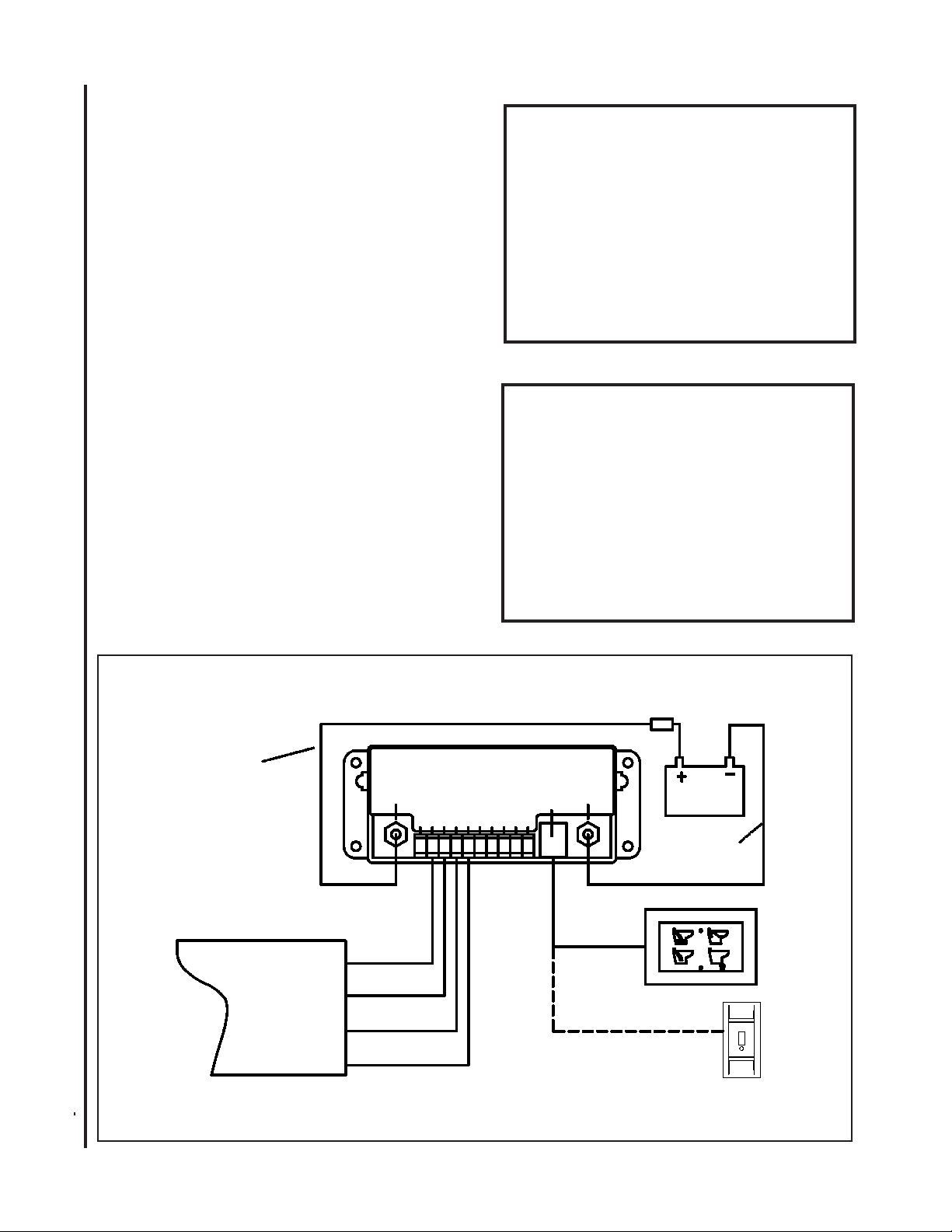
Programming of FlushSense using Optional
Multifunction Control Panel
Multifunction panel Operation and Programming
Optional multifunction panel includes an RJ45 splitter and cable. If installing multifunction panel
permanently then use this splitter to connect both panels; multifunction and FlushSense. If using
Multifunction panel just to program, then connect this panel to RJ45 socket during programming and
reconnect FlushSense panel after programming is done.
HOLDING TANK FULL
WATER
ONLY
RARITAN
EMPTY
ONLY
TOILET FLUSH CONTROL
WATER
SAVER
NORMAL
FLUSH
7
OPTIONAL PANEL
L492 0412vkm

• Once this is done, push the “Normal” button
to store this value (the Holding Tank LED will
ash three times indicating the time has been
set and you have left program mode).
Setting T3 Water retention ll Time:
• Hold WATER ONLY & EMPTY buttons down
together for 3 seconds, The holding tank LED
will give three quick ashes indicating you
have entered program mode - release both but-
tons.
• Push the “Water only” button as many times
as seconds required for the Water Valve/Inlet
Pump time. Note: Minimum is 2 maximum is
8. The Tank LED will ash once indicating a
valid key push.
• Once this is done, push the “Normal” button
to store this value (the Holding Tank LED will
ash three times indicating the time has been
set and you have left program mode).
Programming the WATER ONLY Disable
Features:
1. Hold the WATER ONLY & EMPTY buttons
down together for three seconds. e holding
tank full LED will give THREE ashes indicat-
ing you have entered program mode .
2. Push the WATER SAVER button. e WATER
ONLY and EMPTY buttons now can be disa-
bled or enabled.
3. Pushing the WATER ONLY button will disable
both WATER ONLY and EMPTY buttons. e
holding tank full LED will give THREE ashes
indicating you have le program mode.
4. Repeat steps 1 to 3 to re-enable these buttons.
Programming the WATER ONLY button to only
work aer Empty button is pushed
1. Repeat step 1 & 2 above
2. Pushing the EMPTY ONLY button will enable
this feature. e holding tank full LED will
8
L492 0412vkm Specications Subject to Change Without Notice Printed in U.S.A.
FOR LIMITED WARRANTY TERMS AND CONDITION PLEASE REFER TO TOILET MANUAL
give THREE ashes indicating you have le
program mode.
3. repeat 1 &2 above to disable this feature.
Extending pause before water retention:
1. Some installations require longer pause be-
tween discharge pump and nal retention
water ll to avoid siphoning:
2. Hold the WATER ONLY & EMPTY buttons
down together for three seconds. e holding
tank full LED will give THREE ashes indicat-
ing you have entered program mode .
3. Push the WATER SAVER button. is will
place control in disable/enable mode
4. Pushing the WATER SAVER button again. e
holding tank full LED will give THREE ashes
indicating you have le program mode.
5. Repeat steps 1 to 3 to shorten the pause.
5/64
(2mm) 2 1/4
(57mm)
Mounting Multifunction Panel:
1. Cut out a hole per Fig. 2, mark mounting
holes using wall plate as guide.
2. Route wire to the toilet and control.
3. Secure control using mounting screws
FIG 2. Mounting Multifunction panel
OPTIONAL PANEL
530 Orange Street, Millville, NJ 08332 USA
Telephone: 856-825-4900 FAX: 856-825-4409
www.raritaneng.com
Fort Lauderdale, FL
Telephone: 954-525-0378
Table of contents
Popular Bathroom Fixture manuals by other brands

VIGO
VIGO Cass VG6044 installation manual

Pacific Bay
Pacific Bay JetStream PB-S05 installation manual

ProFlo
ProFlo PF5200CP installation instructions

Wellis
Wellis Caprera Instruction guide

Pfister
Pfister Deckard R89-1DA Quick installation guide

Swiss Madison
Swiss Madison SM-VSF251 installation instructions

for Living
for Living 063-5799-0 Assembly instructions

Hans Grohe
Hans Grohe Focus 190 31608 Series Instructions for use/assembly instructions

Bossini
Bossini OKI Floor L00818 installation instructions

noken
noken Radiador 500x1000 Installation and Maintenance

agape
agape MEMORY AMEM311 Assembly instructions

Jacuzzi
Jacuzzi SPRAY GUARD installation instructions