Troubleshooting and Replacement
(Part # I34M-1 for 120V or Part # I34M220 for 240V Units)
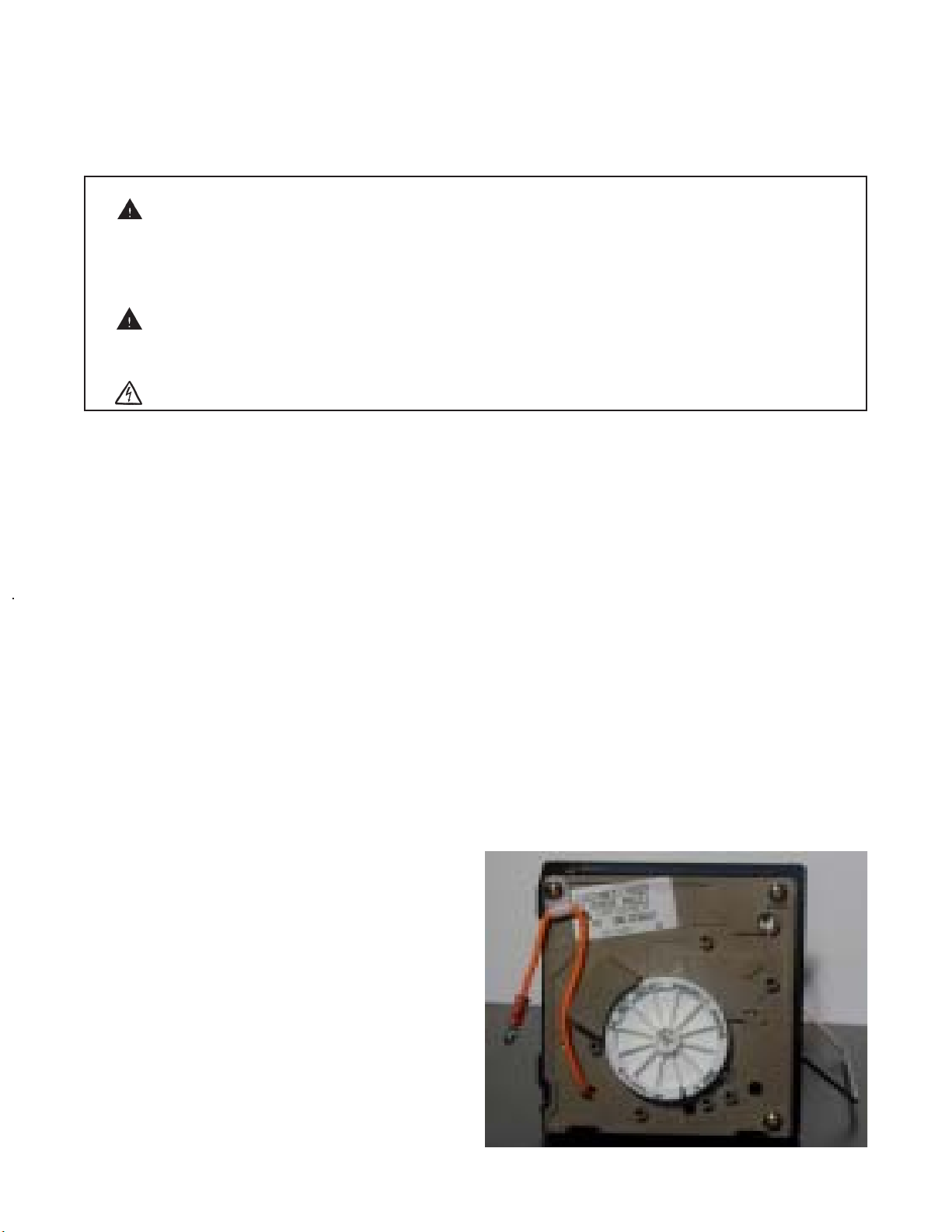
ICEMAKER MODULE BOARD
.
WARNING: RaritanEngineeringCompany,Inc.recommendsthataqualifiedtechnicianinstall,troubleshoot
andrepairthisproduct. Equipmentdamage,injurytopersonnelordeathcouldresultfromim-
properinstallationorunsafeaction. RaritanEngineeringCompany,Inc.acceptsnoresponsi-
bilityorliabilityfromdamagetoequipment,orinjuryordeathtopersonnel thatmayresultfrom
improperinstallationofthisproductorfromunsafeactionstakenbyatechnician.
WARNING: RefrigerationEquipmentcontainsrefrigerantfluidsunderveryHIGHPRESSURE.
Dangerofsuddenpressurereleaseresultingininjury,death,orseverefrostbitemayresultfrom
notfollowinginstructions.
WARNING: HazardofElectricalShock
TROUBLESHOOTING
Toolsrequired: Voltmeter,4"(10.2cm)ofinsulated
#12AWG(4.0mm2)singleconductorjumperwire.
WARNING - HAZARD OF ELECTRICAL
SHOCK: Tests requiresAC power at module.
ProceedusingEXTREMECARE.
NOTE: Theshutoffarmmust be intheDOWN
position.
MODULE NOT FUNCTIONING PROPERLY
Removewhiteplasticfront cover oficemaker
module. Graspcoverfirmlyandpull.
1. Systemisinoperative;notcold.
Thefanandcompressordonotrunwhentheunit
is on. Ejector“fingers”arenotvisable. Normal
positionforejectorfingersisapproximately2:30
o’clockposition. Iffingersareinanotherposition
andarenotmoving,themoduledrivemechanism
isstuckintheEJECTIONCYCLE,themodule
boardmayneedreplacing. Checkforpowerby
placingprobesofvoltmeterintotestpointsL
and N with icemaker on, you should read a
nominal120VAC (or240Vdependingonthe
unitsvoltage). Ifnovoltageisreadonmeter,the
problem may be with wire harness or other
electricalconnection(s).
2. Fanandcompressorrunandicebinisfreezing
coldbutthereisnoiceproduction.
Iftheseconditionsexist,performthefollowing
test:
Makeajumperoutofashortpieceof#12AWG
(4.0mm2)singleconductorinsulatedwire. Bare
both ends by exposing a minimum of 1/2"
(1.3cm)ofuninsulatedwire.
Inserttheuninsulatedendsofthejumper1/2"
(1.3cm)intoterminal portsT&H (seeFig.A).
Thecompressorandfanshouldshutoffandwhite
gearshouldstarttorotateclockwise. Ifgeardoes
notrotate,modulerequiresreplacing. Ifgear
rotatesforonecompletecycle,moduleisokand
moldthermostat(#I34T)shouldbereplaced.
Removejumperafter30seconds.
TH
Fig. A
TH
N
L


