manuals.online logo
Brands
  1. Home
  2. •
  3. Brands
  4. •
  5. Raritan
  6. •
  7. Power Distribution Unit
  8. •
  9. Raritan Dominion Px User manual

Raritan Dominion Px User manual

Dominion PX Quick Setup Guide 1
QSG-DPX-0F-E y255-80-6081-00
Dominion PX
Quick Installation and Setup Guide
Thank you for purchasing the Dominion PX intelligent power distribution unit (PDU).
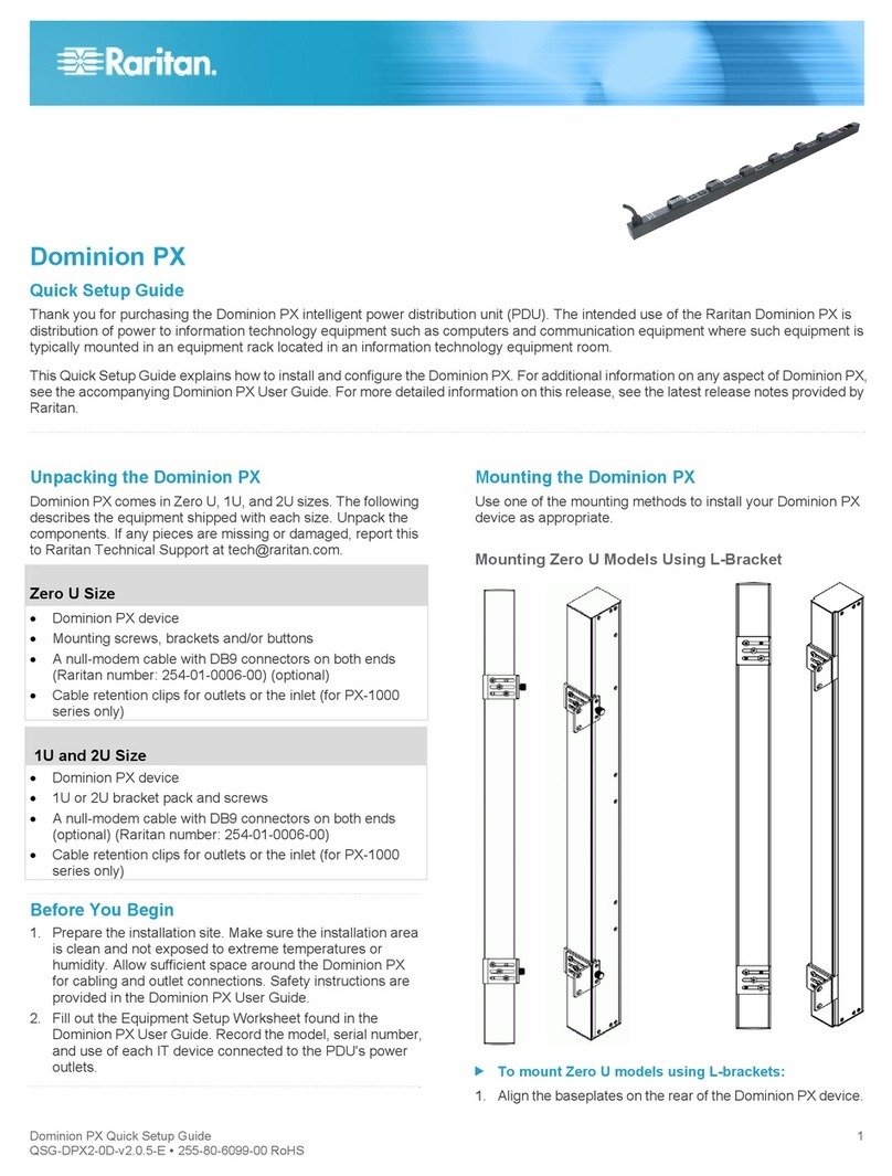
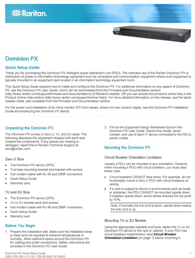
Unpack the Dominion PX
The Dominion PX comes in Zero U, 1U and 2U sizes. The
table below describes the equipment shipped with each size.
Unpack the components, and if any piece is missing or
damaged, report this to Raritan Technical Support at
[email protected].
Zero U Size
DPX unit including power cord 4.5m (15 feet).
Tool-less mounting bracket and bracket with screws.
Null modem cable with RJ-45 and DB9F connectors.
1U and 2U Size
DPX unit including power cord 4.5m (15 feet)
1U or 2U bracket pack and screws
Null modem cable with RJ-45 and DB9F connectors.
QS Rule
Before You Begin
1. Prepare the installation site. Make sure the installation
area is clean and not exposed to extreme temperatures or
humidity. Allow sufficient space around the Dominion PX
for cabling and outlet connections (safety instructions are
provided in the Dominion PX User Guide).
2. Fill out the Equipment Setup Worksheet, found in the
Appendix section of the User Guide. Record the model,
serial number, and use of each device connected to the
Dominion PX's power outlets.
QS Rule
Mount the Dominion PX
Depending on the model, your Dominion PX will require one
of the following mounting options:
For 1U and 2U Models
Using the appropriate brackets and tools, fasten the Dominion
PX to the rack or cabinet.
For Zero U Models Using Claw-Foot Mounts
1. Attach a claw-foot bracket to the back of the Dominion PX.
2. Fasten the Dominion PX to the rack or cabinet by:
a. Using rack screws to secure the unit through the claw-
foot bracket.
b. If using the tool-less mounting bracket align the silver
buttons with the mounting holes in the cabinet, fixing
one in place and adjusting the other. Then let the
Dominion PX drop into place.
For Zero U Models Using L-Bracket
1. Align the base-plates on the back of the
Dominion PX unit and tighten the thumb
screws to secure them in place.
2. Unscrew the large buttons in the center
of the base plates.
3. Align the L-Brackets with the base
plates so that the five screw-holes line
up. The rack-mount side of the plates
should face either the left or right side
of the Dominion PX.
4. Fasten the L-brackets in place with the
large button. Use additional screws as
desired.
5. Using rack screws, fasten the Dominion
PX to the rack through the L-Brackets.
QS Rule
Connect the Dominion PX to a Power Source
1. Each Dominion PX model should be plugged into an
appropriately rated outlet for its type.
2. The Zero U models do not have front panel indicator lights
since they will be mounted in the back of an equipment
rack. When a Dominion PX is powered on, the outlet
LEDs cycle through various colors. Once the internal
Dominion PX Quick Setup Guide 2
QSG-DPX-0F-E y255-80-6081-00
software has finished loading, the outlet LEDs display a
solid color and the meter illuminates.
QS Rule
Connect the Dominion PX to a Computer
1. Connect the RJ-45 end of the null modem cable to the port
labeled Serial on the front of the Dominion PX.
2. Connect the DB9 end of the null modem cable to the serial
port (COM) of the computer.
QS Rule
Connect the Dominion PX to Your Network
1. Connect a standard Cat 5e UTP cable to the LAN port on
the front of the Dominion PX.
2. Connect the other end of the cable to your LAN.
QS Rule
Configure the Dominion PX
1. Go to the computer that you connected to the Dominion
PX and open a terminal emulation program such as
HyperTerminal or PuTTY. Make sure the port settings are
configured as follows:
Bits per second = 9600
Data bits = 8
Stop bits = 1
Parity = None
Flow control = None
2. Point the communications program at the serial port
connecting the unit and open a window.
3. Press Enter. The opening configuration prompt appears.
4. Type config and press Enter. You are now prompted to
enter several networking parameters.
IP address The default IP address is: 192.168.0.192. To
assign the Dominion PX an IP address,
Choose either:
Auto configuration: Select dhcp or
bootp and let the DHCP or BOOTP server
provide the IP address.
Static IP address: Select None and when
prompted, enter a an IP address, network
mask and gateway.
IP access
control
Leave this disabled for now. This disables
the Dominion PX's firewall. You can enable
the firewall and create access control rules
after the initial installation and configuration.
LAN
interface
speed
Leave the default Auto, or select 10 or 100
Mbps.
LAN
interface
duplex
mode
Leave the default Auto, or select half or
full.
5. Once you have entered the network parameters, the
values you entered are shown, and you are asked if they
are correct. If any are incorrect, type n, press Enter, and
go back and change them. When they are correct, type y
and press Enter.
Note: The default IP address is 192.168.0.192. The default IP
configuration method is DHCP, and the default IP address will
be replaced by the address assigned by DHCP or BOOTP, or
the static IP address you entered, as soon as the
configuration process is complete. To use the factory default
IP address, please type in “none” as the IP autoconfiguration
command.
Congratulations! Installation and configuration are complete.
QS Rule
What to do Next
1. Connect devices to the outlets on the Dominion PX.
2. From a computer connected to your LAN, open a browser
and point it at the IP address of the Dominion PX.
3. Enter admin and raritan (lowercase) when prompted for a
username and password.
4. You will be prompted to change the admin password.
Once this is done, the Dominion PX Home page appears.
5. Dominion PX is sent from the factory with all the outlets
ON. Turn OFF the outlets without devices connected from
the Home Page if you wish.
6. Under Device Settings, configure PX with the proper date
and time or synchronize it with an NTP server. Dominion
PX's time must be in sync with the LDAP server to use
LDAP authentication.
7. Use the menu across the top of the page to create user
profiles and groups, set up security, and configure outlet
thresholds.
Note: Detailed instructions are available in the Dominion PX
User Guide.
QS Rule
Safety and Installation Information
Notice
This instruction should be used in conjunction with the
Dominion PX User Guide.
This product must be installed by suitably qualified personnel
in accordance with the requirements of relevant legislation
and regulations for the region (e.g. the National Electric Code
in the USA, the Canadian Electric Code in Canada, the IEE
wiring regulations in UK, etc.) as well as accepted practices in
industry. Any information about the uses for which these
products were designed and tested is available on request.
Installation should be in accordance with any appropriate
Health & Safety regulations.
Dominion PX Quick Setup Guide 3
QSG-DPX-0F-E y255-80-6081-00
Testing
All PDU's are fully tested and verified to conform to the
required standards. Where further system wiring is carried
out, or where the modules are integrated into larger systems,
the entire installation must be tested prior to use as prescribed
by national wiring regulations.

For compliance with certain standards, the installer must test
the complete electrical installation prior to use, and, in general
use, the products should be subject to regular checking. The
frequency of the electrical and visual checks will depend on
the nature of the use to which the PDU is put and as such the
test frequency must be determined by the installer. Guidelines
for normal tests are given below.
Earth Continuity
A current of 25 amps should be passed from an alternating
current (AC) source with a no-load voltage not exceeding 12V,
between the earth conductor of the power supply cord and the
earth connection of the outlet sockets. This test should be
repeated for metal parts surrounding the installation, which
should be earthed.
Where the power cord specified exceeds 3M the 100mΩlimit
common on many PAT testers may be exceeded. This does
not mean the product has failed. The length of the cord should
be checked and the appropriate allowance made.
Conductor Continuity and Polarity
The system should be checked to ensure correct polarity and
continuity of all wiring.
Insulation Resistance
The insulation resistance between LINE/NEUTRAL and
EARTH should be measured using a 500VDC. test supply.
The measured resistance should not be less than 1.0MΩ.
Flash Test
A flash voltage of 1500VAC between LINE/NEUTRAL and
EARTH should exhibit a leakage of under 1mA. Note: where
the power cord exceeds 3M, the unit may exhibit higher
leakage. The appropriate allowance should be made.
Both insulation and flash testing may ONLY be carried out LN-
E. Testing between L-N may give erroneous results due to the
Neon indicator (if fitted).
Notes on units with integral filters
Units with integral filter systems may be LN-E insulation
tested at 500VDC but if flash tested at 1500VAC, they will
exhibit high leakage readings under insulation tests due to the
nature of the filtering components.
The quiescent earth leakage of the filter unit under normal
conditions may be checked and should not exceed 0.9mA at
250V~ 50Hz.
L to N flash and insulation tests would be inconclusive due to
the presence of the filter system and may damage the surge
suppression circuitry.
Uses
This system has been designed to conform to the latest safety
requirements. In addition to compliance with standards for
general use, this PDU has been factory configured for use in
19” rack mounting environments. This does NOT preclude
their use in other situations.
Safety Precations
Ensure all equipment is unplugged before carrying out any
testing.
Testing of this nature should only be carried out by suitably
qualified individuals.
CAUTION: USE ONLY IN DRY LOCATIONS / ATTENTION:
UTILISER UNIQUEMENT DANS DES EMPLACEMENTS
SECS
THE INFORMATION GIVEN IN THIS LEAFLET IS SUBJECT
TO CHANGE WITHOUT NOTICE. ANY GUIDANCE NOTES
ARE GIVEN WITH REGARDS TO COMPLYING WITH
SPECIFIC STANDARDS ARE PROVIDED AS AN AID TO
THE INSTALLER AND ARE INTERPRETATIONS OF THOSE
STANDARDS ONLY.
THESE INSTRUCTIONS ARE PRIMARILY INTENDED TO
PROVIDE DETAILS ON THE SAFE USE AND
INSTALLATION OF THE ABOVE MAINS DISTRIBUTION
SYSTEM.
NOTICE: FOR PLUGGABLE EQUIPMENT, THE SOCKET
OUTLET SHALL BE INSTALLED NEAR THE EQUIPMENT
AND SHALL BE EASILY ACCESSIBLE. THE PRODUCT
MUST BE INSTALLED BY A QUALIFIED ELECTRICIAN IN
ACCORDANCE WITH NATIONAL AND LOCAL
ELECTRICAL CODES.

Other manuals for Dominion Px

5

Other Raritan Power Distribution Unit manuals

Raritan Dominion Px User manual

Raritan

Raritan Dominion Px User manual

Raritan PXE User manual

Raritan

Raritan PXE User manual

Raritan PX2 User manual

Raritan

Raritan PX2 User manual

Raritan Dominion Px User manual

Raritan

Raritan Dominion Px User manual

Raritan PX2 User manual

Raritan

Raritan PX2 User manual

Raritan Dominion Px User manual

Raritan

Raritan Dominion Px User manual

Raritan Dominion Px User manual

Raritan

Raritan Dominion Px User manual

Raritan PXE User manual

Raritan

Raritan PXE User manual

Raritan PX3-4000 series User manual

Raritan

Raritan PX3-4000 series User manual

Raritan PX3-1000 series User manual

Raritan

Raritan PX3-1000 series User manual

Raritan PXE User manual

Raritan

Raritan PXE User manual

Raritan Dominion Px User manual

Raritan

Raritan Dominion Px User manual

Raritan PX2-1000 SERIES User manual

Raritan

Raritan PX2-1000 SERIES User manual

Raritan PX3TS User manual

Raritan

Raritan PX3TS User manual

Raritan PX User manual

Raritan

Raritan PX User manual

Raritan PX-1000 Series User manual

Raritan

Raritan PX-1000 Series User manual

Popular Power Distribution Unit manuals by other brands

EPS 56VDC IPS Series user manual

EPS

EPS 56VDC IPS Series user manual

ETA Systems PD11SP owner's manual

ETA Systems

ETA Systems PD11SP owner's manual

PS Audio Power Director 4.7 Operation manual

PS Audio

PS Audio Power Director 4.7 Operation manual

Philex Powerdome instructions

Philex

Philex Powerdome instructions

Rittal Ri4Power System 185 mm Assembly and operating instructions

Rittal

Rittal Ri4Power System 185 mm Assembly and operating instructions

Schulte Elektrotechnik EVOline Port Assembly instructions

Schulte Elektrotechnik

Schulte Elektrotechnik EVOline Port Assembly instructions

NewMar FDP 1010 Technical practice

NewMar

NewMar FDP 1010 Technical practice

Tripp Lite SUPDM Series owner's manual

Tripp Lite

Tripp Lite SUPDM Series owner's manual

Securitytronix ST-PBX9-24AC-PTC installation manual

Securitytronix

Securitytronix ST-PBX9-24AC-PTC installation manual

Show Tec PSA-32A6S manual

Show Tec

Show Tec PSA-32A6S manual

Channel Plus 2010 user guide

Channel Plus

Channel Plus 2010 user guide

lab12 Gordian owner's manual

lab12

lab12 Gordian owner's manual

Tripp Lite PDUMH15AT owner's manual

Tripp Lite

Tripp Lite PDUMH15AT owner's manual

Tripp Lite PDU15NETLX owner's manual

Tripp Lite

Tripp Lite PDU15NETLX owner's manual

Cord Tech PSOA care guide

Cord Tech

Cord Tech PSOA care guide

Tripp Lite PDUH20HVL6 Information

Tripp Lite

Tripp Lite PDUH20HVL6 Information

Tripp Lite SmartOnline B020-016 6 owner's manual

Tripp Lite

Tripp Lite SmartOnline B020-016 6 owner's manual

Tripp Lite PDUMNH15 owner's manual

Tripp Lite

Tripp Lite PDUMNH15 owner's manual

manuals.online logo
manuals.online logoBrands
  • About & Mission
  • Contact us
  • Privacy Policy
  • Terms and Conditions

Copyright 2025 Manuals.Online. All Rights Reserved.