Part PS/2 SUN USB Serial Video Local Ports Firmware Power Control
Upgradeable
P2CIM-PS2 X HD15 X
UKVMC X HD15 X
UKVMP2 X HD15
UKVMP-x330 X HD15
UKVMC-x330 X HD15 X
UKVMSPD X HD15
P2CIM-SUN X HD15 X
P2CIM-SUSB X X HD15 X
USKVMPA X 13W3
USKVMC X 13W3/HD15 X
P2CIM-USB X HD15 X
AUPUSBC X HD15 X
AUATC X X
Paragon®II
Quick Installation and Setup Guide..
Administrative Setup
Physical Connections
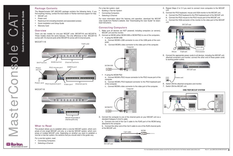
Connect power cord to the Main Switching Unit.
Power ON the Main Switching Unit.
Connect one end of a Category 5e UTP cable to User Port #1 on the back of the Main Switching Unit. Connect the other end of the cable
to the “Cat5 Port” on the back of the User Station (P2-UST)
Connect a power cord to the User Station. Power ON the User Station.
Connect a PS/2 keyboard, mouse, and VGA monitor to the User Station. Power ON the monitor.
Connect one end of a Category 5e UTP cable to Channel Port #1 on the back of the Main Switching Unit (or Stacking Unit, if attached).
Connect the other end of the cable to the RJ45 port on a Computer Interface Module (P2-CIM).
Connect the P2-CIM to server’s keyboard, video, and mouse ports.
Power ON server.
2
1
3
4
5
6
7
8
1. A Login Menu is displayed on the VGA monitor attached to the User Station. In the user name field type
“aaddmmiinn” (all lowercase). Press the [EEnntteerr] key. In the password field type “rraarriittaann” (all lowercase). Press the
[EEnntteerr] key.
2. The monitor displays an On-Screen User Interface (OSUI) Selection Menu with the connected server
displayed in green.
3. Use the [↑↑]or [↓↓]keys to highlight the green channel and press the [EEnntteerr] key.
4. Normal computer access and operation indicates a successful connection.
IIMMPPOORRTTAANNTT: A video gain adjustment is available to “focus” the video image (especially when using LCD flat
panel monitors). Activate the OSUI by pressing the [SSccrroollllLLoocckk] key twice rapidly. Use the numeric key pad [++]
and [--] keys to adjust the video image until it appears “in focus.”
Please consult the Paragon II User Manual for more information on Paragon II installation, setup, and operation.
Rev. B January 2004 255-30-6010
37
8
IIMMPPOORRTTAANNTT: All computers and Paragon II components must be powered OFF prior to installation.
MAIN SWITCHING UNIT (P2-UMT1664M, P2-UMT832M, P2-UMT442,
P2-UMT242) AND STACKING UNIT (P2-UMT1664S, P2-UMT832S)
COMPUTER INTERFACE MODULE (CIM)
MULTI-PLATFORM CIM TABLE
4
5
6
1 2
USER STATION (P2-UST)
OOppttiioonnaallSSttaacckkiinnggSSuuppppoorrtt::
--Connect power cord to a Stacking Unit.
- Connect one end of a stacking cable to the "Expansion Port Out" on the back of the Stacking Unit. Connect the other end of the cable to the "Expansion Port" on the
Main Switching Unit. NNoottee::If installing the P2-UMT1664M, use two stacking cables. Connect one stacking cable to the P2-UMT1664S “Out A” port and connect the
other end to “Expansion Port In” on the P2-UMT1664M. Connect the other stacking cable to the P2-UMT1664S “Out B” port and connect the other end to the remain-
ing “Expansion Port In” on the P2-UMT1664M.
- Power ON all switching units.
- On the front panel LCD of the Main Switching Unit:
= Press the FFUUNNCCbutton and use the [↑↑]and [↓↓]keys to select "Stacking Support." Press the EENNTTbutton.
= Select the total number of Stacking Units desired (0-3). Press the EENNTTbutton.
- On the front panel LCD of the Stacking Unit:
= Press the FFUUNNCCbutton and use the [↑↑]and [↓↓]keys to select "Set Stack ID." Press the EENNTTbutton.
= Assign the Stacking Unit ID using the [↑↑]and [↓↓]keys. EEaacchhSSttaacckkiinnggUUnniittMMUUSSTTHHAAVVEEAAUUNNIIQQUUEEIIDD((11--33))!!
= Press the EENNTTbutton. NNoottee::Sequential order is not necessary.
