rauland Telecenter IV User manual

System
Planning
RI-158lA
Telecenter
IV
Internal System
Planning
RAULAND-BORG CORPORATION l 3450 West
Oakton
Street, Skokie, Illinois 60076-2951 l (708) 679-0900
TABLE OF CONTENTS Page
Introduction
..........................................................................................
1
Introduction to System Planning
........................................................
2
Plan Remote Locations
........................................................................7
Assign Physical Numbers
....................................................................
8
Determine Hardware Requirements
..................................................
9
Determine D.C. Power Requirements
................................................
10
System Planning Worksheet
(blank form)
............................................ 12
Physical Number Layout Planning Worksheet
(blank form)
..............13
Introduction:
This manual is a guide for planning a Telecenter IV installation. Step-by-step procedures and
worksheets are provided to enable a clear, concise, and comprehensive listing of require-
ments for use in ordering, system installation, and programming.
Because the Telecenter IV may or may not be connected to the public telephone network, the
manual is divided into two parts: RI-1581, Internal System Planning; and, KI-1582, Intercon-
nect Planning.
Only the information necessary to plan a system which does not interconnect to the public
utility is included in this manual. No attempt is ma& to describe the system, the functions of
its various components, or how to install, program, test, or troubleshoot the Telecenter IV.
Refer to the appropriate System Manual for this information as required.
1989 Rauland-Borg Corporation
(Orig.
10/88;
Rev.
l/89)
Page 1 of 16

System Planning
Introduction to System Planning
Summary:
FUNCTIONS:
REMOTE
LOCATIONS:
QUANTITY:
TCIV LINES:
This section describes the System
Planning
Worksheet, which
provides space for creating a
clear, concise, and comprehensive listing of system requirements. Using it will help ensure a
correct and
sucessful
cost estimate and provide a useful tool for use when ordering, installing,
and programming the system. Read the following while reviewing the example to get a full
understanding of the worksheet and how to complete it.
The System Planning Worksheet is divided into six major planning areas: Function, Remote
Locations, Quantity (Qty.),
TCIV
Lines, Physical Numbers (Phys.
#),
and Cabling. An ad-
ditional block at the bottom provides space for planning additional Display requirements.
The following paragraphs explain each area and how it should be completed.
Functions are chosen according to the operational features desired by the customer. They es-
tablish the requirements for Remote
Location
and TCIV Line hardware. Space is provided so
that four different Staff functions (A, B, C, D) can be defined on one sheet. This should be
enough in most cases. Definitions and special notes should be written on the worksheet
where ever appropriate.
These are the stations where people use Phones, Speakers, and Switches to perform a func-
tion associated with a single line. In the example, a
1 in
any
Phone
or Speaker block indi-
cates one unit is required at each remote location.
Switches
are designated by type
E
(Emergency), N (Normal), and
P (Privacy).
A horizontal line indicates the item is not needed
in the example system.
Shadowed areas
indicates the option doesn’t apply in any system.
(i.e., Speakers and Switches cannot be on the same line as a Call Control Console or
Key
Phone and
TC4160
VCM’s
and TC4171
COA’s
require TCIV lines
but they are not used by
people at remote locations).
Phones: The
example system uses several types of phones to support a variety of functions. It
includes a Display Phone, three
Key
Phones, an Administrative Phone, and twenty
Multi-Link Staff Phones. (Note: Multi-link phones can be identied by looking at
their
LLM
and Physical
Number requirements. Only multi-link staff phones
require one LLM line and one physical number each.) Another Staff Function
(Staff-
D) could be specified for single- link staff phones and only one physical number
would be required for all of them. However, each of them would use a Phone
SCC25 line.
Speaker: The example system requires 43 speakers. One at each remote location performing
a Staff function (A, B, or C).
Switch:
The example system requires 15 Normal and 15 Emergency switches: one of each
type of switch at each remote location performing the
Staff
-
B
function.
(QTY.): This is the total number of each type of Function required. In the example system
there is:
1
Display Phone, 8
Staff
-
A
stations (each requiring a speaker), 15
Staff
-
B
stations
(each requiring a speaker with a normal and an emergency call-in switch), and 20
Staff
-
C
stations (each requiring a phone and speaker). There are also 6 Central
Office
Trunks and
3
Key
Phones.
This is where you determine the
Phone
and
Speaker
hardware required to meet the needs
determined by the number and types of Functions and Remote Locations.
Phone
equipment is required to support telephone and hands-free intercom paths. The
amount of hardware required is determined by the number of TC4 150 Line-Link Module
Page
2
of
16
1989
Rauland-Borg Corporation
(Orig.
10/88; Rev.
l/89)


System Planning
(LLM) lines and
TC4120
(SCC25)
Speaker Control lines needed. In the example, there are no
requirements for
SCC25s,
indicating that there are no single-link staff phones in the system.
However, the example does require, 47 LLM lines (5 for the System, 1 for the Display Phone,
6
for the
Trunks/COAs,
5 for the
3
Key
Phones, 10 for the Administrative Phones, and 20 for
the Staff
-
C locations).Note that in this example, all three key phones get the same five line.
If each of the three key phones had one unique line, they would require 7 LLM lines (4
common and
3
unique lines).
Speaker equipment is required to support one-way communication paths for paging,
time-
zone signals, and other functions. The amount of hardware required is determined by the
total number of
TC4110
(SC25)
Speaker Control lines needed. In the example system,
43
Speaker SC25 lines are required: 8 lines for the 8 Staff
-
A locations, 15 lines for the 15 Staff
-
B locations, and 20 lines for the 20 Staff
-
C locations.
(Note:
When
determining
SC25 and
SCC25 requirements, do not exceed 2 amps A.C.
(5OW)
through any single SC line.)
PHYSICAL (Phys.
#): This is
where you list the set of physical numbers (P:) which will support each
NUMBER:
Function. Except for Key Phones and the
TC4400
Call Control Console, the physical number
range must be equal to the figure in the Quantity column. Physical numbers for Key Phones
must be equal to the number of unique lines required. The System
(P:O
-
4) and Display
Phone
(P:5)
physical numbers are standardized and should not be changed. Physical number
assignments for the example system are:
Trunks/COA’s
(P:6
-
1
l),
Key Phones
(P:
12
-
16),
Ad-
ministrative Phones
(P:17
-
26),
Staff-A
(P:
16
-
23),
Staff
-
B
(P:47
-
61),
and Staff
-
C
(P:27
-
46).
The system software uses physical numbers to keep track of the equipment
connected
to
each line and to access attribute programming on how each line should be handled (see
KI-
1584 for theprogramming associated with physical numbers).
Assigning
physical numbers is
one of the most complex and important parts of system design. The following paragraphs de-
scribe the mechanics of assigning physical numbers.
Physical numbers relate to pins on the SC25 and SCC25 (SC) and
TC4150
LLM
boards. They
are assigned in groups of consecutive numbers which provide the required overlap
between
LLM
and SC boards. This overlap is required when speakers and phones are placed at a staff
location and required to work as a unit. However, when a multi-link phone is used without a
speaker, the
speaker circuit may be used elsewhere for paging and zone-signalling. In
the
example, physical numbers 17
-
23 overlap in this manner
(P:
16
-
23 are used for Staff A
corridor speakers and
P:
17
-
26 are used for Administrative Phones).
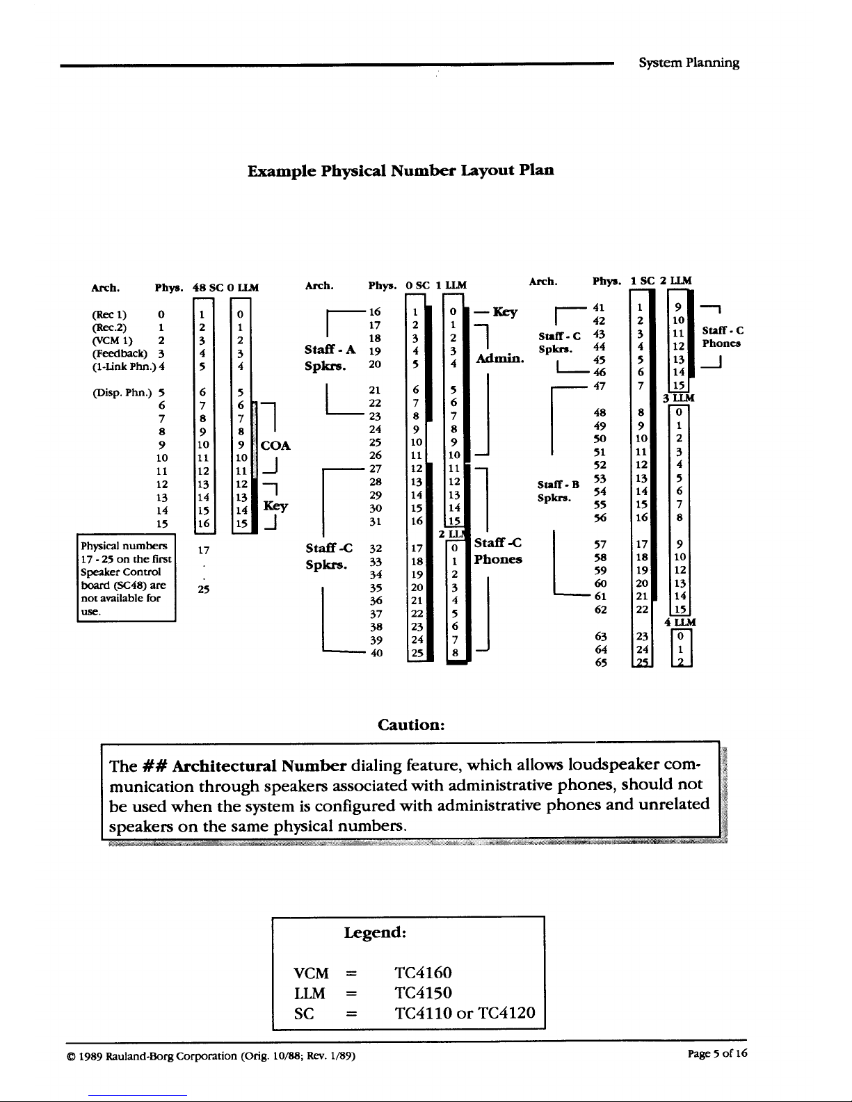
A
Physical Number
Layout
Planning Worksheet is
provided at the back of this manual. It
shows every physical number in the system and the relationship between physical numbers
and pin numbers on LLM and SC boards. The
Example Physical Number Layout Plan
on
the
facing page shows these relationship for the example system. (Shaded bars have been
drawn to show relationships at a glance. This could also be accomplished using colored
pencils, to mention but one option.)
CABLING:
In this column, the type of cabling required between remote locations and the Telecenter
cabinet is noted. Where possible, standard cable requirements are predesignated. Cabling for
Key Phones is instrument dependent, as is cabling for Administrative and Staff functions.
Cable types are noted according to the legend at the bottom right of the worksheet. (
A
for a
shielded pair,
B
for 3 conductors with a shield, C for a twisted pair, and
D
for
3
shielded
pairs). Cabling requirements
can be determined using the
Riser Diagram
(KMO895).
DISPLAYS:
The box
at the bottom of the worksheet provides space for recording TM432 Graphics An-
nunciator Module
(GAM)
and TC4200 Vacuum Fluorescent Display (
VFD)
requirements.
These requirements are separately itemized because they do not require communication lines
from either Line-Link Modules or Speaker Control Boards.
Page 4 of 16
1989 Rauland-Borg Corporation
(Orig.
10/88;
Rev. l/89)


System Planning
Plan Remote Locations
Summary:
Use the
System
Planning
Worksheet
and complete the information required under
headings: Function,
Remote Locations,
and
Quantity.
This
will
provide all the information
necessary to determine the size and cost of the required system.
Step 1.
Make a copy of the
System Planning Worksheet
and note on it any other information which
will be useful during later stages of planning, installation, and programming (e.g., the name
of the site, the contact person, phone number, etc.).
step 2. Obtain or create a scaled
diagram
showing the physical layout of the
customer’s facility,
including: all rooms, hallways, doorways, entrances, exits, and parking areas, conference
rooms, bathrooms, etc. This will be useful in achieving total coverage, for use as a
guide to
the installer,
and for
estimating
cabling
costs.
NOTE:
Step
3.
While performing Steps
3
through
5,
have a copy of the System Planning Worksheet and the
scaled diagram at hand to ensure all options can be reviewed with the customer.
Review the System Description and facility drawing with the customer to determine the
following system requirements and complete the Function and Remote Locations areas of the
System Planning Worksheet.
LCD Display
phone:
These
are recommended for use as Attendant Phones and for
system programming. A display phone may be coupled with a speaker and any combina-
tion of call-in switches.
VFD (Vacuum Fluorescent Displays): One VFD is required at each location staffed by
Attendant stations which do not
have
display phones.
Note:
LCD Drivers 1 and 2 can each drive up to
3
displays (LCD and VFD).
The
drive ca-
pability can be increased with buffers (contact Sales Engineering).
VCM: The
TC4001
comes equipped with one VCM, supplying one intercom chan-
nel for use by all speakers. Additional
VCMs
must be installed if more than one intercom
channel is desired. Note that only one VCM (one intercom channel) is allowed per
Speaker Control board.
Administrative Phones:
One is needed for each user who will dial calls and page.
Staff:
Specify as many different types (A, B, C, etc.) of staff stations needed for the
application and determine the number (Quantity) required of each. The following
examples are
from
the previously discussed system:
Staff
-
A is
a Stand-alone speaker for a corridor, etc.
Staff
-
B is
a
Stand-alone speaker with both Normal and Emergency switches for
rooms with infrequent communication requirements.
Staff
-
C is
a Multi-Link Staff Phone with speaker for rooms with frequent
communication requirements.
1989
Corporation
(Orig.
Rev.
l/89) Page
7
of
16

System Planning
Graphic Displays:
Use the following steps to determine graphic display requirements for one location.
Double the figures obtained if a second location is required. Refer to the System Descrip-
tion and
Progra
mming Manuals (RI-1580 and RI-1584) for information on utilizing the
graphic display drivers.
A.
B.
C.
D.
E.
F.
Determine the total number of annunciated lines required and provide one GAM
(TM432)
for each set of thirty-two lines. Call-ins on any of these lines should light
a lamp or LED.
Determine the total number of monitored lines required and provide one
GAM
(TM432)
for each set of thirty-two lines. A lamp or LED should light when any of
these lines are in-use.
Provide
a
pulse generator if a flashing indication is desired for either the annunci-
ated or monitored lines. If both types of lines are required to flash, but at
differ-
ent rates, a pulse generator may be required for each.
Design and obtain materials for a custom display panel, allowing mounting space
for the TM432 modules.
For each type of line (annunciated and monitored) provide a
34-conductor
flat
cable long enough to supply lamp driver signals to each GAM, plus enough slack
for maintenance purposes. Also, provide one connector for each GAM and an
additional connector for test purposes, if desired.
Determine the power requirements and ensure local power is available. Provide
back-up power if necessary.
Step 4.
If interconnect
is
required:
Go to the Interconnect Planning Guide (KI-1582) to determine requirements for
the
TC4400
Call Control Console,
Trunks/COAs,
and
Key
Phones.
Step 5.
Review the Riser Diagram and note all cabling requirements on the System Planning
Worksheet.
Page 8 of
16
1989 Corporation
10/88;
Rev. l/89)

System Planning
Assign Physical Numbers
Physical numbers are used by system software to keep track of equipment
connected
to each
of the 5 12 possible lines; therefore, each
TC4150
Line Link Module
(LLM)
and each
TC4110
(SC25)
and TC4120 (SCC25) Speaker Control line in the system has a physical number. The
first step in assigning physical numbers is determining how many lines are required from
Line-Link Modules
(LLM)
and Speaker Contol (SC)
boards.
Then, physical numbers can be
assigned using the Physical Number Iayout Worksheet.
step 1.
Step 2.
Step
3.
Refer to the
Quantity column
of your
System Planning Worksheet
and enter the number of
LLMMlines required for each of the following:
TC4160
VCM
(additional
VCM’s
only: VCM 1 has a dedicated LLM line.)
TC4400
Console
(1 LLM line is required for the Console)
Trunks/TC4171
COA’s
(1 LLM line per
trunk/COA)
Key Phones (1 LLM line per unique Key Phone Line: Do not multiply by
the number of
Key
Phones if they all use the same lines.)
Administrative (1 LLM line per Administrative Phone)
Multi-Link Staff
(1 LLM line per phone: Refer to your Staff function defini-
tions for the quantity of Multi-Link phones required.)
A Phone SC line is required for each Single-Link Staff Phone. Refer to your definition of Staff
Functions
for the quantity of Single-Link phones required and enter that number on the
appropriate function line under
Phone
SCC25.
A Speaker
SC
line is required for each Speaker.Refer to the
Quantity column
of your
System Planning Worksheet
and enter the number of Speaker SC25 lines required for each
function.
Step 4.
Make a copy of the
Physical Number Layout Worksheet
and define a set of physical num-
bers for each function, keeping the following in mind:
Assign physical numbers in a way that makes maximum use of resources. This will
help
minimize
system costs.
Group like equipment together and add physical numbers to allow room for system
growth. This is especially important for
Trunks/COAs,
Administrative Phones, and
Multi-Link Staff Phones because they use LLM lines, which are generally more limited
in number than SC lines.
Use a colored pencil or some other method to code groupings of physical numbers by
function. This graphic depiction will allow a quickassessment of
free
LLM and SC
lines.
After completing the physical number assignment, determine if additional lines can
be added to any of the groups from the unused lines at the end of the physical
number range.
1989
Rauland-Borg Corporation
(Orig.
10/88; Rev.
l/89)
Page 9 of l6

System Planning
Determine Hardware Requirements
Summary:
The final step in system planning is dete
rmining
what hardware is required to install and
operate the system as designed. The TCIV System Ordering Guide should be completed in
accordance with the following steps.
Step 1.
Step 2.
Step 3.
Step 4.
step 5.
If speakers are to be used by a paging or audioprogra
mming source (e.g.,
Director Series)
other than the Telecenter IV, determine the number and type of switch panels required
(SW25 or SWT425) and order one
TC4110
(SC25) for each.
Determine the total number of
SCC25
Speaker Control boards required by subtracting the
number of
SC25s
determined in Step 1
from
the total number of Speaker Control boards
required to meet the established physical number layout plan.
Determine the number of
TC4140
LLM
expansion chassis required
by subtracting one (1)
from the total number of
LLM’s
required and dividing the remainder by Eve (5). Increase the
quotient to the next whole number if a fraction is obtained.
Determine the number of TC4165
VCM
expansion chassis required by subtracting one (1)
from
the total number of
VCMs
required and dividing the remainder by four (4). Increase the
quotient to the next whole number if a fraction is obtained.
Determine Power Amplifier requirements for
All
Page by summing the output power re-
quirements of all speakers in the system. Order a Power Amplifier which will meet current
and anticipated needs.
Step 6.
Determine Power Amplifier requirements for Zone Page by summing the output power re-
quirements of all speakers in each zone. Order a Power Amplifier which will meet current and
anticipated needs of the zone with the highest power requirement.
step 7. If more than one
TC4160
VCM is required, determine power supply requirements using the
following formula and the steps on the next page.
Step 8.
Provide lightning protectors for any lines which go outside the building (Drawing KM0714).
D.C. Power Requirement Formula
MI0
+ CPU +
MTGlOO
=
1.80
LLM
Off-Hook Phones
Number
X
.08
=
Number
X
.04
=
VCM2s:
Idle
2w
12w
Number
Number
Number
X
.30
=
X
.66
=
X 2.40 =
Total Amps
=
Page lO of 16

System Planning
Determine D.C. Power Requirements
Summary:
The Telecenter IV standard 12 Vdc power supply is adequate unless unusual demands
are
placed
on the system. Use the example shown below and complete the following
steps
to de-
termine
if
additional
power handling capacity is required.
The example represents
a system with
5
TC4150
LLM’s
and 3
TC4160
VCMs.
One 10 watt
speaker is used and all others are under 2 watts each. It is assumed that at most 20 phones
will be off-hook at once and that it is possible for three administrative phones to place simul-
taneous intercom calls (no idle
VCM’s)
.
The result of the computation (6.72 amps) indicates the
TC4OOls
built-in 5 amp power
supply is insufficient. To install all three
VCMs,
a separate 4.0 amp regulated power supply is
required.
step 1.
Note the total number of TC4150
LLMs
in the system in the formula for
LLMs.
step 2. Estimate themaximum number of multi-link phones that may be off-hook at any given time.
(32 off-hook phones will use all sixteen lines.) Note this number in the formula for Off-Hook
Phones.
Step 3.
Review the power rating of each speaker assigned to each VCM.
Note the number of
VCMs
with
all
speakers rated at no more than than 2 watts in the
formula for
2W
VCMs.
Note the number of
VCMs
with any speaker rated above 2 watts in the formula for
12w
VCMS.
step 4. Estimate themaximum number of administrative phones that may make simultaneous
intercom calls. Subtract this number
from
the total number of
VCMs
installed and note the
remainder in the formula for IDLE VCMS.
Step 5.
Perform the indicated calculations to determine the system total power requirement and plan
for additional power if it exceeds 5 amps.
D.C. Power Requirement Formula
(Example)
MI0
+ CPU +
MTGlOO
=
1.80
Off-Hook Phones
Number
5
X
.08
=
.40
Number 20 X
.04
=
.80
VCM2s:
Idle
2w
12w
Number
Number
Number
X
.30
=
2
X
.66
=
1.32
1
X
2.40
=
2.4
Total Amps
=
6.72
1989
Rauland-Borg
Corporation
(Orig.
10/88;
Rev.
1b.39)
Page 11 of
16


Other manuals for Telecenter IV
1
Table of contents
Other rauland Conference System manuals
Popular Conference System manuals by other brands

Munters
Munters Rotem Communicator Manual for use and maintenance

Cisco
Cisco TelePresence SX20 Installation sheet

Polycom
Polycom SpectraLink 6000 System installation guide

Mircom
Mircom TX3 Series Installation and operation manual

Danish Interpretation Systems
Danish Interpretation Systems DCS 6000 user manual

Avaya
Avaya Scopia XT4200 Quick setup guide