Ravendo 164014 User manual

164014 | 164114
electric
heavy duty
trolley

2
PURPOSE
The purpose of this user manual is to
ensure correct use and maintenance of the
heavy duty trolley. The heavy duty trolley is
motorized and designed to transport heavy
goods. The heavy duty trolley is mano-
euvred by one person using a tiller head.
READING INSTRUCTIONS
Knowledge
It is the responsibility of the employer (ow-
ner of the machine) to ensure that everyone
who is operating, servicing, maintaining or
repairing the machine has read the user
manual; at least the parts of it that are
relevant to their work.
In addition, everyone who has to operate,
service, maintain or repair the machine has
a duty to search information in the user
manual themselves.
Availability
The user manual must be kept in a place
known to the staff where it is easily avai-
lable to operators and maintenance staff.
VERSION
This user manual is an English translation
of the manufacturer’s original user manual.
This user manual is version 1.1
MANUFACTURER
Ravendo A/S is the manufacturer and pro-
ducer of the heavy duty trolley.
Ravendo A/S
Klokkestøbervej 3-5, DK 8800 Viborg
+45 86 44 73 11
www.ravendo.com
SERVICE PARTNER FOR MOTOR AN ELEC-
TRONICS
IMMO A/S is the supplier of and service
partner for the motor and electric system of
the heavy duty trolley.
IMMO A/S
Friis Hansens Vej 9, DK 7100 Vejle
+45 75 85 80 22
hello@immodenmark.dk
www.immodenmark.dk
INTENDED USE, WARNINGS
ABOUT DANGEROUS SITUATIONS
Always use the required personal protective
equipment when handling the heavy duty
trolley and the goods being transported.
Protective footwear must be used when
using the electric warehouse trolley.
The heavy duty trolley must only be used
with original and correctly mounted acces-
sories and spare parts. Never use the pro-
duct with other parts than those supplied
together with the product or specically
adapted to the purpose by Ravendo A/S
Never try to modify or adapt the product for
any use other than that described in the
user manual. In the event of modication or
change of use, any warranty and liability of
the manufacturer will become void.
Before each use of the heavy duty trolley,
check that the trolley is in a safe condition
and that the electric system is undamaged.
During use, the operator must be aware
of changes in driving characteristics and
make sure that any damage is repaired
before using the heavy duty trolley again.
ABOUT THIS USER MANUAL
SAFETY

3
PRODUCT VIEW.......................................................................................................................
USER INSTRUCTIONS .............................................................................................................
DRIVING INSTRUCTIONS .......................................................................................................
CHARGING INSTRUCTIONS ...................................................................................................
TRANSPORT OF THE TROLLEY ..............................................................................................
MAINTENANCE .......................................................................................................................
MAIN FUSE REPLACEMENT ...................................................................................................
SERVICE ..................................................................................................................................
WARRANTY..............................................................................................................................
TROUBLESHOOTING ......................................................................................................................
TECHNICAL SPECIFICATIONS.................................................................................................
CONFORMITY DECLARATION.................................................................................................
WIRING DIAGRAM...................................................................................................................
SPARE PART LIST ...........................................................................................................................
4
6
8
10
12
12
12
13
13
14
16
17
18
19
CONTENTS

4
PRODUCT VIEW
Mechanical brake
Mounting holes for
corner posts and sides
Trolley with corner posts Trolley with corner posts and sides
Load platform
Top plate
Tiller head
Machine plate

5
Motor
Charging socket
Batteries
Main fuse
Control box
Motor
Disengagement
Traction wheel
Front wheel

6
BETJENINGSVEJLEDNING
TILLERHEAD
A: Status light
B: Horn
C: Accelerator and driving direction
D: Belly-button
E: Key switch
A: STATUS LIGHT
The status light indicates whether the
heavy duty trolley is on or off as well as
any error messages on the electric system.
When the status light is on, the trolley is on.
If the status light is off, this indicates that
the heavy duty trolley is off or out of power.
If the status light is ashing, this refers to a
given error code. In case of error code, you
need to count the number of ashes – see
further description in the section “Troubles-
hooting”.
B: HORN
The heavy duty trolley is equipped with a
horn. When pressing the button, the horn
makes a signal sound.
C: ACCELERATOR AND DRIVING DIRECTION
The accelerator is stepless and determines
the current driving speed and direction. The
more the accelerator is tilted, the faster the
heavy duty trolley drives. When tilting the
accelerator up, the trolley moves forward.
When tilting the accelerator down, the
trolley moves backwards. When you relea-
se the accelerator, it returns to its home
position after which the heavy duty trolley
stops. The two accelerators are intercon-
nected and can be used simultaneously or
individually with one hand.
D: BELLY-BUTTON
Belly button/change of direction is a safety
function that makes the heavy duty trolley
move forward upon activation. This is a
safety measure so that the trolley moves
B
A
C C
D
E
forward/away from the user upon activation
to prevent any danger of crushing the user
when driving backwards.
E: KEY SWITCH
Used for switching the heavy duty trolley
on and off. To switch on, insert the key and
turn it a quarter turn clockwise. To switch
off, turn the key a quarter turn counter-
clockwise, after which the key can be rem-
oved. It is recommended always to remove
the key and take it with you when leaving
the heavy duty trolley to secure against
unauthorized use.
MOTOR AND FRAME
F: Charging socket
G: Disengagement

7
H: Mechanical brake
F: CHARGING SOCKET
The charging socket is used to charge the
batteries of the heavy duty trolley. Please,
follow the charging instructions page 12.
G: DISENGAGEMENT
If you need to push the heavy duty trolley
manually, the motor can be disengaged
using the handle on the motor located at
the rear of the trolley (G).
For disengagement, turn the handle dow-
nward. Always switch off the heavy duty
trolley and use the mechanical brake befo-
re you engage or disengage.
To deactivate the disengagement, pull the
disengagement handle up until you feel a
click. It is only possible to drive the hea-
vy duty trolley via the tiller head and the
motor, when the disengagement is deacti-
vated. If you try to switch on the heavy duty
trolley with the disengagement activated,
the status light (A) ashes. To reset this
error, turn off the heavy duty trolley and
deactivate the disengagement. Turn the
trolley on again and it is ready for use.
REMEMBER: Always deactivate the disen-
gagement after use if it has been activated.
WARNING! When you disengage, the brake
will be disengaged and you should take
care that the heavy duty trolley does not roll
away from you. Always use the mechanical
brake of the heavy duty trolley, when disen-
gaged.
H: MECHANICAL BRAKE
On the front wheel of the heavy duty trolley,
there is a mechanical braking function. Tilt
the handle bar to the vertical position to
activate the mechanical brake.
FG
The mechanical brake activated
The mechanical brake deactivated
H
H
Tilt the wheel down approximately to ho-
rizontally to deactivate the mechanical
brake. The heavy duty trolley may only be
manoeuvred when the handle bar is tilted
down and the mechanical brake is thus
deactivated.
WARNING! Do not leave the trolley without
the mechanical brake activated.

8
THE FIRST DRIVE WITH THE HEAVY DUTY
TROLLEY
The rst time you drive the heavy duty trol-
ley, you should drive without any load and
in a place with plenty of room, preferably on
a at and rm surface without obstacles.
When you are familiar with manoeuvring
the heavy duty trolley on at surfaces, you
should practice driving with one hand as
well as driving over and around obstacles
such as over kerbs and on ramps. As you
become more comfortable with mano-
euvring the heavy duty trolley, you can drive
with fastened goods. Further description of
the driving can be read in the below section.
Only when you are fully familiar with the
operation and manoeuvring of the heavy
duty trolley in the above-mentioned diffe-
rent scenarios, the trolley can be used for
daily work.
DRIVING THE HEAVY DUTY TROLLEY
Before driving the heavy duty trolley:
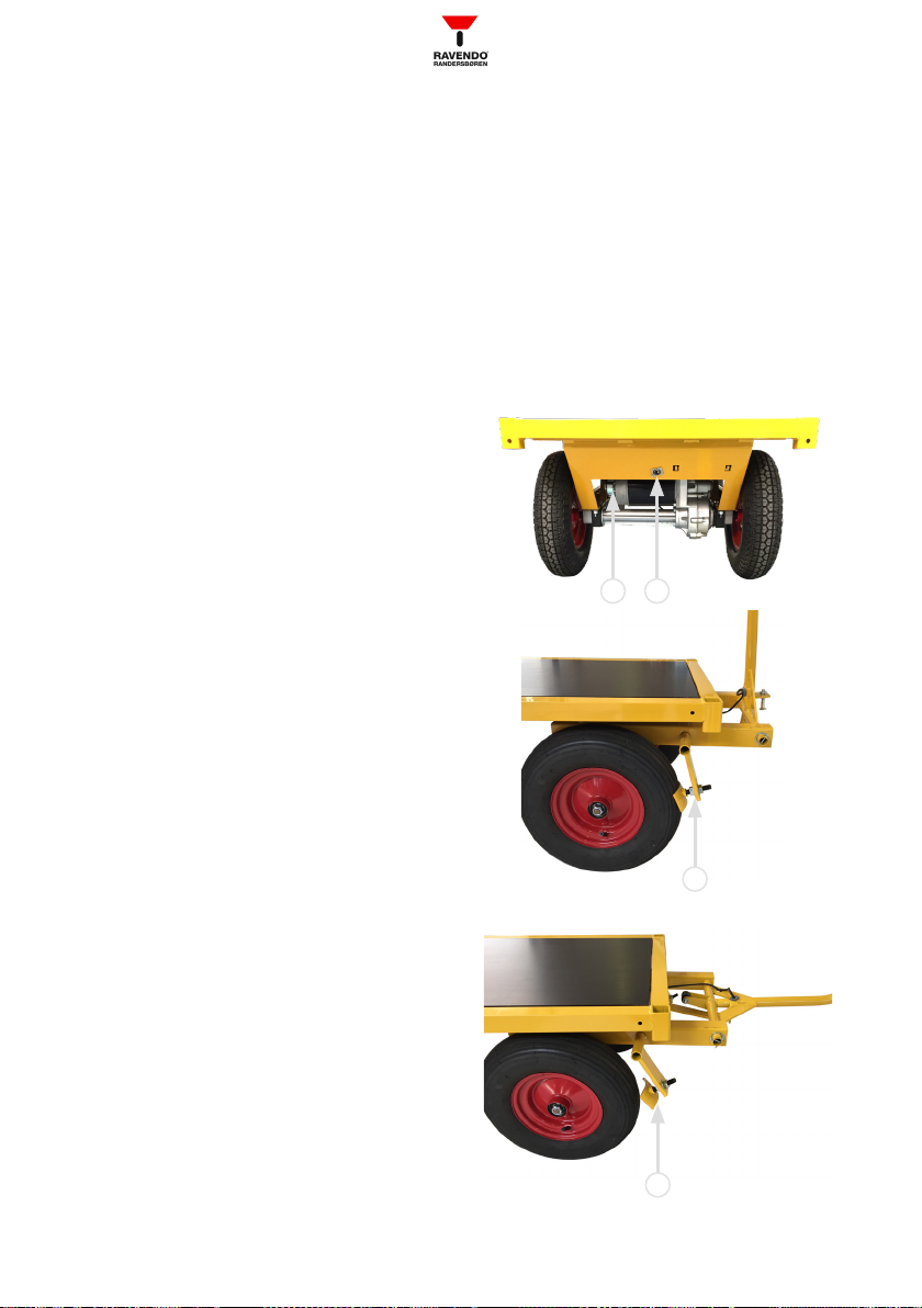
1. Prior to driving, check that the disengage-
ment (G) is deactivated and that the bat-
teries are fully charged (green light in the
charger). If the disengagement is not deac-
tivated, please do so. Turn off the charger
and remove the charger from the heavy duty
trolley’s charging socket (F).
2. Tilt the handle bar down to deactivate the
mechanical brake (H).
3. Switch on the heavy duty trolley by inser-
ting the key in the key switch (E) and turn
the key a quarter turn clockwise. When the
heavy duty trolley is on, the status light (A)
lights up green. If the heavy duty trolley is
switched on before the charger is discon-
nected, this will result in an error message.
Switch off the heavy duty trolley, disconnect
the charger, and switch it on again
The heavy duty trolley is now ready to go.
In case of error on the electrical system,
the status light ashes in a given sequence
which can be read to nd the reason for
the error. See ”Troubleshooting” or contact
IMMO A/S.
Driving
The trolley is manoeuvred by means of the
tiller head’s handles and accelerators.
4. Tilt the accelerator (C) up or down for
forward or reverse movement. The more
the accelerator is tilted, the faster the
heavy duty trolley moves. The accelerator is
spring-loaded and automatically returns to
its home position, when the pressure is re-
lieved or the accelerator is released. When
the accelerator is returned to its home
position, the heavy duty trolley decelerates
to a stop. When stopped, the parking brake
is automatically activated.
If you lose control of the heavy duty trolley,
release the accelerator to stop while still
holding the handle of the tiller head.
5. To turn the heavy duty trolley, pull the
tiller head in the direction you want to turn.
REMEMBER: Always look for possible ob-
stacles in the driving direction and adapt
the speed accordingly.
Fastening of goods
It is the driver’s responsibility to ensure that
the goods transported on the heavy duty
trolley are properly fastened during driving
to prevent them from falling off.
After driving/use
6. If the heavy duty trolley is parked for a
shorter period, make sure that the wheels
are locked. It is always recommended to tilt
the handle bar up so that the mechanical
DRIVING INSTRUCTIONS

9
brake is activated when the trolley is not in
use.
7. Always switch off the heavy duty trolley
and take the key with you when leaving it to
secure against unauthorized use.
8. After use, drive the heavy duty trolley to
the charging place. Switch off the trolley
by turning the key a quarter turn counter-
clockwise. Always connect the charger and
check that the LED of the charger is lit for
correct connection.
ALWAYS REMEMBER to switch off the heavy
duty trolley and connect the charger after
use. This also applies if the heavy duty trol-
ley is not to be used for a longer period.
If necessary, clean the heavy duty trolley;
see further description for this under ”Main-
tenance”.
MANUAL DRIVE WITH DISENGAGED MOTOR
If you need to push the heavy duty trolley
manually, without using the motor, this can
be disengaged. This is done via the disen-
gagement lever (G) Se further description
under ”User instructions”.
When the motor is disengaged, the trolley
can be manoeuvred via the tiller head hand-
le without using the accelerator.
NOTE: When the motor is disengaged, the
automatic parking brake is also disengaged.
Therefore, make sure that the heavy duty
trolley does not roll away from you. Always
use the mechanical brake of the heavy duty
trolley.

10
The below charging instructions apply to the
supplied standard charger, Victron Energy
Impulse S8. Charging must take place in dry
frost-free environment with good ventilation.
If charging is carried out below 10°C, redu-
ced mileage must be expected.
WARNING! During charging, explosive gas
may be generated under certain circum-
stances. Never charge near ignition sources
and ensure good ventilation.
Only use the supplied charger, Victron Ener-
gy Impulse S8, or a charger approved by the
manufacturer. When using a charger other
than the standard charger, the indications
and charging time described below may
be different. Always read the user manual
that comes with the charger in question.
Use of other chargers not approved by the
manufacturer may result in damage to the
electric system with the risk of explosion
and/or re.
CHARGER CONNECTION/CHARGING:
1. Switch off the heavy duty trolley with the
key switch (E) before charging.
2. Connect the charger plug (I) in the char-
ging socket (F).
3. Insert the charger plug (K) in a wall
socket and turn the wall socket on. NOTE:
For safety reasons the heavy duty trolley is
designed so that it cannot drive, when the
charger is connected.
4. When the charger is connected, the lamp
to the left (J) on the charger rst lights up
YELLOW, which indicates that the batteri-
es are being charged. When the charging
is complete and the batteries are fully
charged, the lamp to the right (J) lights up
GREEN, and the heavy duty trolley is ready
for use.
5. To be able to use the heavy duty trolley,
the charger must be disconnected. To
disconnect the charger, switch off the power
outlet, then remove the charger plug from
the trolley’s charging socket (F). Follow the
“Driving instructions” on page 10 for use of
the heavy duty trolley.
When the batteries are fully charged, the
charger maintains the charge with a very
low current. This ensures that the battery is
kept fully charged and helps to extend the
battery life. Therefore, it is recommended to
connect the heavy duty trolley to the char-
ger when it is not being used.
NOTE: If you use the heavy duty trolley
outdoor all year round, you will nd that the
mileage increases when the weather is hot.
Charger: Victron Energy Impulse S8F: Charging socket on trolley
CHARGING INSTRUCTIONS
F
I J K

11
Conversely, the mileage will be shortened in
cold weather. This is perfectly normal for a
battery-powered vehicle.
BATTERIES AND CHARGING TIME
The batteries are maintenance-free. Always
make sure to connect the charger when the
heavy duty trolley is not in use. This helps
to extend the battery life.
Usually, it takes up to 10 hours to charge
the batteries. If the batteries are complete-
ly at, the charging may take longer. Avoid
running the batteries completely at as this
signicantly shortens the battery life.
The batteries slowly lose power if the trolley
is unused. The loss is 10-20% per month
depending on climate conditions and the
conditions of the batteries.
If you experience that the heavy duty trolley
can no longer run as far as before or lacks
traction, this may be due to the batteries
being worn out and having to be replaced.
The battery is a wear part, which may need
to be replaced approx. every third year.
Replacement of the batteries must only be
performed by trained staff. For replacing
of batteries, contact Ravendo A/S or your
dealer.
WARNING! If the batteries are punctured,
and you come in contact with the gel-like
acid in the batteries, remove any contami-
nated clothing and wash skin thoroughly
with soap and water. In case off subse-
quent eczema or rash, seek medical advice.
In case of contact with eyes, rinse immedi-
ately with plenty of water and seek medical
advice.
WARNING! The batteries contain large
amounts of energy. Short-circuiting or da-
mage of the batteries may result in explosi-
on and risk of death.
Waste or defective batteries must be colle-
cted and recycled in accordance with regu-
lations laid down by the local environmental
authorities. Possible waste from defective
batteries must be collected and disposed
of in accordance with local regulations.

12
The heavy duty trolley can be transported in
an ordinary service or delivery van when the
drawbar is removed.
The heavy duty trolley must be securely
fastened to the van’s anchorage points
so that it cannot slip during acceleration
or hard braking. Fastening is the driver’s
responsibility.
Use a suitable ramp to get the heavy duty
trolley in and out of the van. Observe the re-
quirements for maximum gradeability listed
under technical specications.
The heavy duty trolley is best cleaned with
water with a mild soap and a hard-wrung
cloth. Avoid rinsing with running water and
be especially careful not to get water in the
electric parts. Do not use solvents or clea-
ning agents that contain abrasive particles
as this can damage the surfaces of the
heavy duty trolley.
In addition to cleaning, the maintenance of
the heavy duty trolley mainly consists of
regularly checking the tires and wheel
tracks, that all screws and bolt joints are
tightened, and checking the individual parts
for damage and wear.
Worn or damaged parts must be replaced
before using the heavy duty trolley again.
For purchase of spare parts, assistance
with maintenance or repair, contact Raven-
do A/S or your dealer.
To replace the main fuse, follow the nine
steps described below. Always make sure
that the batteries are disconnected corre-
ctly before replacing the fuse. Only replace
the defective fuse with a new one of the
same type and rated current [A/ AMP].
Installing a stronger fuse is a circumvention
of a safety function and may result in re or
explosion.
1. Switch off the trolley via the key switch
and make sure the charger is NOT connec-
ted.
2. Lift the top plate of the load platform and
place it on the ground.
3. Disconnect the batteries.
4. Dismount the protective cover of the fuse
holder.
5. Replace the fuse with a corresponding
fuse.
6. Ret the protective cover on the fuse
holder
7. Connect the batteries
8. Put the top plate back on the load plat-
form.
9. Test drive the heavy duty trolley in a place
with plenty of room.
Only replace the fuse once. If the fuse blows
again immediately after replacement, there
is a fault in the electric system and the
trolley needs to be repaired.
TRANSPORT OF THE TROLLEY
MAINTENANCE
MAIN FUSE REPLACEMENT

13
Service of the heavy duty trolley must only
be performed by a technically knowled-
geable and trained person. Working with
the electric installations of the heavy duty
trolley is highly dangerous for unskilled
persons. Before working on the motor and
the other electric parts, the batteries must
be disconnected.
WARNING! Short-circuiting of the batteries
can cause an explosion and risk of death.
Only original spare parts supplied by Raven-
do A/S or a supplier approved by Ravendo
A/S may be used.
Ravendo A/S and IMMO A/S are responsi-
ble for design, manufacturing and material
defects on the delivered goods for 12
months from the delivery date. Ravendo
A/S is obliged to remedy deciencies due
to design, manufacturing and material
defects. For parts that are replaced under
warranty, the warranty period is 6 months
from the replacement, however, a maximum
of 12 months from the original delivery. The
manufacturer’s liability lapses if the product
has been subjected to incorrect installation,
inadequate maintenance or treatment that
does not comply with the product’s instruc-
tions.
The manufacturer’s liability does not cover
consequential damages, operating losses,
loss of time, loss of prots, costs in connec-
tion with dismantling and shipping of de-
fective goods and other indirect expenses
for the buyer. Products, spare parts and
related services that Ravendo A/S or IMMO
A/S sell and deliver to the customer are
intended for the use described in the user
manual and for use in the EU and Norway.
Notwithstanding any conicting terms in the
agreement basis, the manufacturer is in no
case liable for losses or damages that can
be attributed to use for other purposes or
for use in the EU and Norway.
WARRANTY
SERVICE
WARNING! The batteries contain large
amounts of energy. Short-circuiting or da-
mage of the batteries can cause an explosi-
on and risk of death.

14
TROUBLE-SHOOTING
The heavy duty trolley’s electric system
consists of several interconnected compo-
nents, all of which are important so that the
daily operation can take place safely and
properly. In the event of operational disrup-
tions, the system is programmed to prevent
further driving in most cases. This is to en-
sure a high level of safety for the user and
the context in which the trolley is used.
The motor control has a built-in simple
diagnostic system for decoding the fault.
The diagnostic system communicates by
the status lamp (A) located in the tiller head
ashing in a sequential pattern. The pat-
tern consists of a long pause, a number of
ashes, a short pause and another number
of ashes.
The sequence is repeated until the fault
has been rectied or the heavy duty trolley
is switched off via the key switch. The two
described number of ashes in the sequen-
ce represent the rst and second digits of
the error code. For example, the following
sequence • •••• will indicate error code
1.4. To rectify the fault, contact IMMO A/S
or your dealer. When contacting the dealer
or the manufacturer you will be asked to
inform the machine number, which is stated
on the machine plate located on the under-
side of the tiller head.
In fault-free condition where the heavy duty
trolley is ready to drive or is driving, the
status light is permanently on.

15
Fejlkode Afsnit Forklaring Mulig fejlkilde
1.1 Thermal fault Under or over
temperature
1: Temperature >80°C or below -10°C
2: Excessive load
3: Driving in extreme temperature
4: Automatic brakes does not release
1.2 Throttle fault Fault, throttle pot fault
1: Defective wiring connection between the
tiller head and the control box
2: Defective signal error to accelerator
1.4 Undervoltage fault Battery voltage too low
1: Battery voltage below 17V
2: Poor connection between battery and
motor control
1.5 Overvoltage fault Battery voltage too high
1: Battery voltage above 31V
2: Attempt to drive with the charger
connected
(3: Poor battery connection)
2.1 Main Off Fault Main relay control
defective
1: Main relay in motor control does not
respond as expected
2.2 Motor stalled Motor stalled 1: Motor is blocked
2.3 Main fault Main relay defective
1: Main relay in motor control does not
respond as expected
2.4 Main On Fault Main relay control
defective
1: Main relay in motor control does not
respond as expected
3.1 Wirering fault HPD error > 10 sec.
1: The accelerator is constantly activated
2: Fault on wire to accelerator
3: Fault on potentiometer for accelerator
3.2 Brake On fault Brake system fault
1: The disengagement is activated
2: The brake output is constantly active
3: The brake solenoid is disconnected
3.3 Precharge fault Brake system fault 1: Brake output short-circuited
2: Brake output defective
3.4 Brake Off fault Brake system fault 1: Brake output disconnected
2: Brake solenoid short-circuited
3.5 HPD fault Accelerator active at start 1: Accelerator not in neutral position
2: Potentiometer error
4.1 Current sense fault Current measurement
outside safe area
1: Short-circuit in motor or wires
2: Motor control fault
4.2 Hardware failsafe Unexpected reaction from
motor control
1: Motor control defective
2: Motor carbon brushes worn
3: Motor defective
4.3 EEPROM Checksum
fault
Motor control memory
error
1: Motor control defective or incorrectly
programmed
4.4 Motor open Motor disconnected 1: Motor or motor wires disconnected
2: Motor carbon brushes worn
4.5 Battery disconnect
fault Battery disconnected
1: Battery disconnected
2: Poor connection in battery or plug connec-
tions to battery

16
Heavy duty trolley TW 1500 Item No. 164014
Dimensions
See below illustration
H1: 1.600 mm, B: 700 mm, L1: 1.700 mm
H2: 650 mm, B: 700 mm, L2: 2.900 mm
H3: 470 mm, B: 700 mm, L3: 1.500 mm
Wheels Pneumatic: 4.00 x 8. Hub:
20/25 x 85 mm.
Steel rim with ball bearings
Deadweight 146 kg Speed Up to approx. 5 km/h
Batteries 75Ah Motor power 1200 W
Heavy duty trolley TW 2000 Item No. 164114
Dimensions
See below illustration
H1: 1.600 mm, B: 1.000 mm, L1: 2.200
mm
H2: 650 mm, B: 1.000 mm, L2: 3.400
mm
H3: 470 mm, B: 1.000 mm, L3: 2.000 mm
Wheels Pneumatic: 4.00 x 8. Hub:
20/25 x 85 mm.
Steel rim with ball bearings
Deadweighy 160 kg Speed Up to approx. 5 km/h
Batteries 75Ah Motor power 1200 W
Charger - charging time 8A – 10 hours Gradeability Op til 10º
Load capacity - trolley 1000 kg Operation environment -10/+40°C, 10-90% RH,
Non-condensing
TECHNICAL SPECIFICATIONS
H2
B
L2
H1
B
L1
H3
B
L3
Charger - charging time 8A – 10 hours Gradeability Up to 10º
Load capacity - trolley 1000 kg Operation environment -10/+40°C, 10-90% RH,
Non-condensing

17
CONFORMITY DECLARATION
Ravendo A/S
Klokkestøbervej 3-5
DK-8800 Viborg
Hereby declares that our product
Heavy duty trolley, type number 164014
• has been designed according to all relevant parts of the Machinery Directive 2006/42/EC
• has been tested and approved according to the following harmonized standards:
EN 6100-6-1
EN 6100-6-2
EN 6100-6-3
EN 6100-6-4
EN 61439-2
Viborg, September 2019

18
1
1
2
2
3
3
4 5
A A
B B
C C
D
Key Switch
10 (12)x0,25mm2
Tiller Head
BK 6mm2
RD
BK
RD 6mm2
YL
BU
RD
BN
RD 2,5mm2
ORA
OR
BU
YL
RD
PK
WT
YL
ORA
ORA
BK
BK
BK
GN
BK
OR
BN
GY
GN
RD
GY
GY
RD 1mm2
BK 1mm2
VI
BK
BK
OR 2,5mm2
X1
Ladestik
+
1
-
2
INH
3
Curtis 1212 Battery
BATTERY B+
BATTERY B-
F1
60A
Curtis 1212 J2
RX J2-1
B- J2-2
TX/CHARGE INHIBIT J2-3
B+ J2-4
F3
T1A 5x20mm
AUX Switches, Lid
1
2
3
4
5
6
7
8
9
10
Curtis 1212 Brake+Motor
BRAKE+ J3-1
BRAKE- J3-2
MOTOR M1
MOTOR M2
Bremse m ed kontakt
M
Motor
Throttle / Belly
1
2
3
4
5
6
7
8
9
10
BT2
BATTERY
WT = White = Hvid
BN = Brown = Brun
GN = Green = Grøn
YL = Yellow = Gul
GY = Gray = Grå
PK = Pink = Lyserød
BU = Blue = Blå
RD = Red = Rød
BK = Black = Sort
VI = Violet = Lilla
OR = Orange = Orange
BT1
BATTERY
Curtis 1212 J1
U1
POT WIPER / THROTTLE J1-1
POT HIGH J1-2
HORN J1-3
MODE J1-4
KEYSWITCH INPUT J1-5
INHIBIT J1-6
B+ J1-7
POT LOW J1-8
SPEED POT J1-9
STATUS LED J1-10
BDI J1-11
REVERSE SW J1-12
B- J1-13
PUSH SW / E. REVERSE* J1-14
Horn
+
WIRING DIAGRAM

19
SPARE PART LIST
Product image Item No. Product name
2235C Control box
2049A Battery
1060 Main fuse
1267 Main fuse holder
2186 Charger
2144 Key
3013 Motor/Gear
2230 Tiller head
2178A Charging socket
Only use original spare parts or spare parts that have been approved in advance by Ravendo A/S
or IMMO A/S. Use of non-original spare parts or non-original accessories will void any warranty
and liability of the manufacturer. For purchase of spare parts, please contact Ravendo A/S.

www.ravendo.com
This manual suits for next models
1
Table of contents