Raycap PowerPlus System 100-3-1U Series Operation and maintenance manual

www.raycap.com
INSTALLATION INSTRUCTION & OPERATION MANUAL PowerPlus System 100-3-1U
INSTALLATION INSTRUCTION & OPERATION MANUAL
PowerPlus System 100-3-1U Series
100-3-1U-3
100-3-1U-2


INSTALLATION INSTRUCTION & OPERATION MANUAL PowerPlus System 100-3-1U
www.raycap.com
© Raycap | All rights reserved. •(320-1398) QRC | Rev.B
Page 1 of 30
Table of Contents
1. Copyright............................................................................................................................................................ Page 2
1.1 Disclaimer .........................................................................................................................................2
1.2 Warnings ...........................................................................................................................................2
2. Introduction................................................................................................................................................................... 3
3. Package Contents......................................................................................................................................................... 3
3.1 Prerequisites .....................................................................................................................................3
3.2 Tools..................................................................................................................................................3
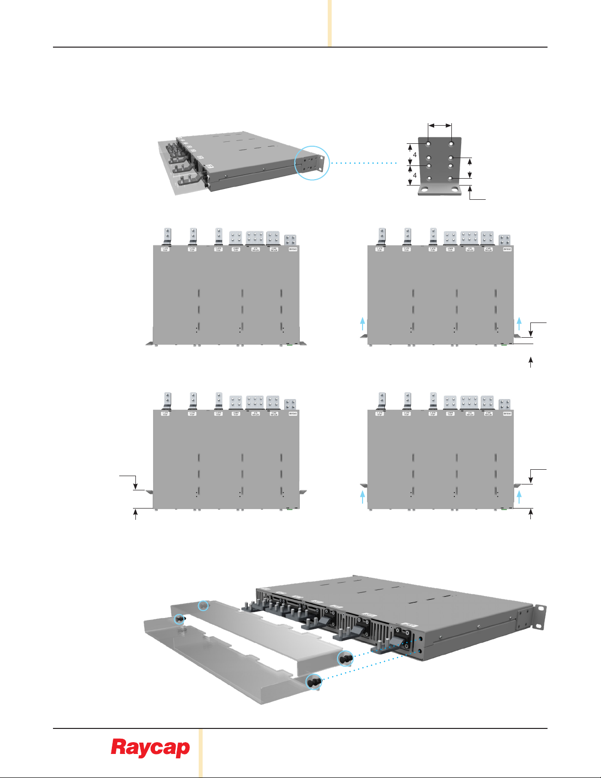
4. Mounting .......................................................................................................................................................................4
5. General Description ...................................................................................................................................6
5.1 Functionality ......................................................................................................................................6
5.2 Modes of Operation...........................................................................................................................6
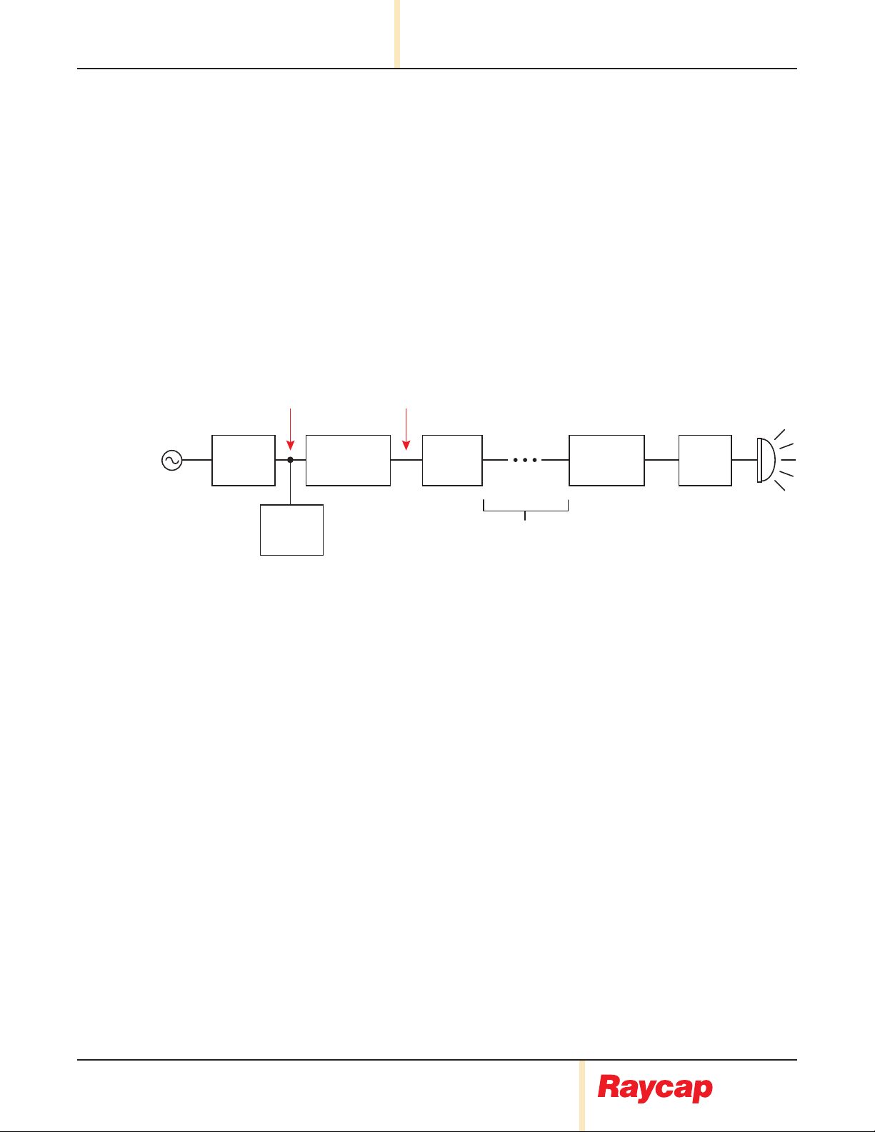
5.3 System Topology ...............................................................................................................................7
5.4 InstallationCongurations.................................................................................................................8
5.5 ModuleCongurations .................................................................................................................9-13
6. System Management................................................................................................................................14
6.1 Modules...........................................................................................................................................14
6.2 Module Failure.................................................................................................................................15
6.3 Primary Failure................................................................................................................................15
7. Modules.....................................................................................................................................................16
7.1 Module Replacement ......................................................................................................................16
7.2 Cold Module Replacement..............................................................................................................17
7.3 Hot Module Replacement................................................................................................................17
7.4 Hot Module Replacement: Invalid Module Installation.....................................................................17
8. Module Settings........................................................................................................................................18
8.1 Settings Menus ...............................................................................................................................18
8.2 Initial Settings Menu........................................................................................................................18
8.3 Initial Settings Menu: Mode Selection .............................................................................................19
9. Parallel Mode Settings .............................................................................................................................20
10. Single Mode Settings...............................................................................................................................21
11. Live Settings Menu...................................................................................................................................22
12. Bus Bar......................................................................................................................................................24
13. Alarms .......................................................................................................................................................25

PowerPlus System 100-3-1U INSTALLATION INSTRUCTION & OPERATION MANUAL
www.raycap.com
(320-1398) QRC | Rev.B •© Raycap | All rights reserved.
Page 2 of 30
1.0 Copyright
©Raycap, Inc. 2021 - All Rights Reserved
1.1 Disclaimer
Theinformationinthisdocumentissubjecttochangewithoutnoticeanddescribesonlytheproductdenedintheintroduction
of this documentation. This documentation is intended for the use of Raycap customers only for the purposes of the agreement
underwhichthedocumentissubmitted,andnopartmaybeused,reproduced,modiedortransmittedinanyformormeans
without the prior written permission of Raycap. The documentation has been prepared to be used by professional and properly
trained personnel, and the customer assumes full responsibility when using it. Raycap welcomes customer comments as part
of the process of continuous development and improvement of the documentation.
Raycap has made all reasonable efforts to ensure that the instructions contained in this document are adequate and free of
material errors and omissions. Raycap will, if deemed necessary explain issues which may not be covered by this document.
The contents of this document are subject to revision without notice due to continued progress in methodology, design and
manufacturing. Raycap shall have no liability for any error damage of any kind resulting from the use of this document.
1.2 Warnings
Please read this manual prior to use to become familiar with the product’s numerous features and operating procedures. To
maintain the maximum degree of safety, follow the sequences as outlined.
Before using the product, read all instructions and cautionary markings on the product and on any equipment connected to the
product.
CAUTION – Unless otherwise noted, product usage that is not recommended or sold by the product manufacturer can result in
riskofre,electricshock,orinjurytopersons.
CAUTION – Do not operate the product if it has been damaged in any way. Return damaged products to their manufacturer for
repair or replacement.
CAUTION –
A) Elevated Operating Ambient - if installed in a closed or multi-unit rack assembly, the operating ambient temperature of the
rack environment may be greater than room ambient. Therefore, consideration should be given to installing the equipment in
an environment compatible with the maximum ambient temperature of 55°C.
B)ReducedAirFlow-Installationoftheequipmentinarackshouldbesuchthattheamountofairowrequiredforsafe
operation of the equipment is not compromised.
C) Mechanical Loading - Mounting of the equipment in the rack should be such that a hazardous condition is not achieved due
to uneven mechanical loading.
D) Circuit Overloading - Consideration should be given to the connection of the equipment to the supply circuit and the effect
that overloading of the circuits might have on overcurrent protection and supply wiring. Appropriate consideration of equipment
nameplate ratings should be used when addressing this concern.
E) Reliable Earthing - Reliable earthing of rack-mounted equipment should be maintained. Particular attention should be given
to supply connections other than direct connections to the branch circuit (e.g. use of power strips).
F) The supply input voltage ranges between -58Vdc to -40 Vdc (+/- 0%).
G) Rated Output Power (kW) = Input Voltage (Vdc) *275 (A).

INSTALLATION INSTRUCTION & OPERATION MANUAL PowerPlus System 100-3-1U
www.raycap.com
© Raycap | All rights reserved. •(320-1398) QRC | Rev.B
Page 3 of 30
2.0 Introduction
In a split Radio Base Station (RBS) architecture the typical RBS consists of a Base Band Unit (BBU) and Remote Radio
Heads (RRH) connected by cabling. Power to the RRH is provided through copper cables traveling from the base station
to the top of the tower or roof top. This creates a conductive path, making the active equipment at the top and the base of
the site vulnerable to damage by direct lightning strikes. Protection systems installed in front of both the BBU and the RRH
must be able to withstand direct lightning currents in order to protect the sensitive equipment. Raycap’s RRH solutions
featuring Strikesorb®SPDtechnologysignicantlyenhancethereliability&availabilityoftheRRHsitebyprovidingsuperior
electrical protection at the RRH and BBU. PowerPlus is Raycap’s solution for power transmission to the RRH units of a DAS
Telecommunication site. PowerPlus is a system installed at the PSU output that boosts the voltage at the base of a cellular site
to overcome the voltage drop on the DC power cables that provide power to the RRHs.
3.0 Package Contents
1 each
(1) 1U PowerPlus System
(1) Rack Extension Kit for 23" racks
(4) 12-24 screws (for use with rack mount brackets)
(1) Bridge output busbar
(1) Lug mounting hardware set
(1) Touch guard set
(1) Cable Kit
3.1 Prerequisites
This document describes how to install the 100-3-1U on-site and how to program the modules.
InstallersofRaycap’sRRHber/powermanagementsolutionsmustbeindustryprofessionalswhohaveattendedtrainingon
theproperhandlingandinstallationofber-opticcable,andattendedtrainingontheinstallationoftheequipmentbyRaycap
and/or the mobile operator. Installers are required to read this installation guide thoroughly prior to installation of the Raycap
RRH management equipment.
3.2 Tools
#2 Phillips screw driver
(2) 7/16" wrenches

PowerPlus System 100-3-1U INSTALLATION INSTRUCTION & OPERATION MANUAL
www.raycap.com
(320-1398) QRC | Rev.B •© Raycap | All rights reserved.
Page 4 of 30
4. Mounting
4.1 Select a suitable position for the installation of the unit. You will need 1U vertical space.
4.2 The unit ships with a Rack Extension Kit to mount into a 23" rack.
4.4 Mount the unit on the rack.

INSTALLATION INSTRUCTION & OPERATION MANUAL PowerPlus System 100-3-1U
www.raycap.com
© Raycap | All rights reserved. •(320-1398) QRC | Rev.B
Page 5 of 30
4.4.1 Mounting Distance from 19" rack
Note:Mountingearpositionsofferthefollowingmountingcongurations
4.5 Release the 4 push pins and remove touch guard as shown below.
Mounting Position A1
Mounting Position A3
Mounting Position A2
0.59
0.94
0.93
0.36
0.94
0.94
2.74
2.14
Mounting Position A4

PowerPlus System 100-3-1U INSTALLATION INSTRUCTION & OPERATION MANUAL
www.raycap.com
(320-1398) QRC | Rev.B •© Raycap | All rights reserved.
Page 6 of 30
5. General Description
5.1 Functionality
• The PowerPlus 100-3-1U system is intended to boost the voltage of a telecom power supply to reduce
the current on the power cables. The output voltage of the system remains constant to a value that is
usercongurableduringitsinstallation.
• By reducing the current, the cable power losses are reduced, and the total system becomes more
efcient.
• Additionally,thePowerPlus100-3-1Uisbenecialwhenoperatingonbatterybackuppowerduringa
poweroutage.ThePowerPlus100-3-1Uwillmaintainaconstantoutputvoltage(ascongured)tothe
radio while the battery discharges. This allows the radio to operate for a longer period of time while
the batteries discharge.
5.2 Modes of Operation
• The PowerPlus 100-3-1U system is composed of a mounting rack and up to three pluggable modules.
• The PowerPlus 100-3-1U system may operate in one of two modes. The Single Mode and the
Parallel Mode.
• The voltage output of each module is intended to be connected to individual loads when the device is
conguredtooperatein Single Mode.
• ThemoduleoutputsmaybeconnectedinparallelwhenthedeviceisconguredtooperateinParallel
Mode.Inthisconguration,theloadissharedbetweentheinstalledmodules.
PowerPlus 100-3-1U Connection Diagram
AC/DC
Converter
-54Vdc -58Vdc
Utility PowerPlus
Rack Mount
Unit Module
Raycap
OVP
(Base)
Raycap
OVP
(Tower Top)
Voltage Drop
on DC Cable
(∆V)
RRH
Battery
Bank

INSTALLATION INSTRUCTION & OPERATION MANUAL PowerPlus System 100-3-1U
www.raycap.com
© Raycap | All rights reserved. •(320-1398) QRC | Rev.B
Page 7 of 30
5.3 System Topology
-48VDC
OUT 1
-48VDC
OUT 2
-48VDC
OUT 3
-48VDC
IN
RTN OUT
RTN IN
GROUND

PowerPlus System 100-3-1U INSTALLATION INSTRUCTION & OPERATION MANUAL
www.raycap.com
(320-1398) QRC | Rev.B •© Raycap | All rights reserved.
Page 8 of 30
5.4 Installation Congurations
PowerPlus100-3-1Usystemcongurations
SINGLE MODE
-48VDC OUT 3
-48VDC OUT 2
-48VDC OUT 1
RTN OUT
-48VDC
RTN
GND
DC
PS
PARALLEL MODE
-48VDC OUT
RTN OUT
DC
PS
-48VDC
RTN
GND

INSTALLATION INSTRUCTION & OPERATION MANUAL PowerPlus System 100-3-1U
www.raycap.com
© Raycap | All rights reserved. •(320-1398) QRC | Rev.B
Page 9 of 30
5.5 Single Module Conguration
PDU
RTMDC-5634-PF-48
RNSNDC-7771-PF-48
RTMDC-4983-RM-48
-48V
OUT
-48V
IN
Return
OUT
Return
IN
GROUND
Power Plus
Conguration 1 (For applications requiring 100 AMPS or less)
100 AMP
Breaker
Recommended Lugs
For 2 Gauge Use:
Panduit LCD2-14-Q
for Input & Output
For 6 Gauge Use:
Panduit LCD6-14A
for Ground
Torque:
All PowerPlus terminal
connections are
¼-20 studs.
Torque to 65 in-lbs.
THE WIRE GAUGE SHOULD BE A MINIMUM OF 2AWG OR 1/O
COPPER WIRE FOR INPUT & OUTPUT
LARGER DIAMETER CONDUCTORS IS ACCEPTABLE.
100 AMP
Module
Installed
Trunk to
Upper OVP
Use #6 AWG
copper wire
for ground

PowerPlus System 100-3-1U INSTALLATION INSTRUCTION & OPERATION MANUAL
www.raycap.com
(320-1398) QRC | Rev.B •© Raycap | All rights reserved.
Page 10 of 30
5.6 2-Module in Single Conguration
PDU
Power Plus
-48V
OUT
-48V
IN
Return
OUT
Return
IN
GROUND
RTMDC-5634-PF-48
RNSNDC-7771-PF-48
RTMDC-4983-RM-48
Conguration 2 (For applications requiring 200 AMPS or less)
200 AMP
Breaker
Use #6 AWG
copper wire
for ground
100 AMP
Module
Installed
100 AMP
Module
Installed
Trunk to
Upper OVP
Recommended Lugs
For 2 Gauge Use:
Panduit LCD2-14-Q
for Input & Output
For 6 Gauge Use:
Panduit LCD6-14A
for Ground
Torque:
All PowerPlus terminal
connections are
¼-20 studs.
Torque to 65 in-lbs.
THE WIRE GAUGE SHOULD BE A MINIMUM OF 2AWG OR 1/O
COPPER WIRE FOR INPUT & OUTPUT
LARGER DIAMETER CONDUCTORS IS ACCEPTABLE.

INSTALLATION INSTRUCTION & OPERATION MANUAL PowerPlus System 100-3-1U
www.raycap.com
© Raycap | All rights reserved. •(320-1398) QRC | Rev.B
Page 11 of 30
PDU
Power Plus
-48V
OUT
-48V
IN
Return
OUT
Return
IN
GROUND
RTMDC-5634-PF-48
RNSNDC-7771-PF-48
RTMDC-4983-RM-48
200 AMP
Breaker
Conguration 3 (For applications requiring 200 AMPS or less)
100 AMP
Module
Installed
100 AMP
Module
Installed
Trunk to
Upper OVP
5.7 2-Module in Parallel Conguration
Use #6 AWG
copper wire
for ground
Recommended Lugs
For 2 Gauge Use:
Panduit LCD2-14-Q
for Input & Output
For 6 Gauge Use:
Panduit LCD6-14A
for Ground
Torque:
All PowerPlus terminal
connections are
¼-20 studs.
Torque to 65 in-lbs.
THE WIRE GAUGE SHOULD BE A MINIMUM OF 2AWG OR 1/O
COPPER WIRE FOR INPUT & OUTPUT
LARGER DIAMETER CONDUCTORS IS ACCEPTABLE.

PowerPlus System 100-3-1U INSTALLATION INSTRUCTION & OPERATION MANUAL
www.raycap.com
(320-1398) QRC | Rev.B •© Raycap | All rights reserved.
Page 12 of 30
5.8 3-Module in Single Conguration
PDU
Power Plus
-48V
OUT
-48V
IN
Return
OUT
Return
IN
GROUND
RTMDC-5634-PF-48
RNSNDC-7771-PF-48
RTMDC-4983-RM-48
Conguration 4 (For applications requiring 300 AMPS or less)
300 AMP
Breaker
100 AMP
Module
Installed
100 AMP
Module
Installed
100 AMP
Module
Installed
Trunk to
Upper OVP
Use #6 AWG
copper wire
for ground
Recommended Lugs
For 1/O Gauge Use:
Panduit LCD1/O-14A-X
for Input
For 2 Gauge Use:
Panduit LCD2-14A-Q
for Output
For 6 Gauge Use:
Panduit LCD6-14A-L
for Ground
Torque:
All PowerPlus terminal
connections are
¼-20 studs.
Torque to 65 in-lbs.
THE WIRE GAUGE SHOULD BE A MINIMUM OF 2AWG OR 1/O
COPPER WIRE FOR INPUT & OUTPUT
LARGER DIAMETER CONDUCTORS IS ACCEPTABLE.

INSTALLATION INSTRUCTION & OPERATION MANUAL PowerPlus System 100-3-1U
www.raycap.com
© Raycap | All rights reserved. •(320-1398) QRC | Rev.B
Page 13 of 30
5.9 3-Module in Parallel Conguration
PDU
Power Plus
-48V
OUT
-48V
IN
Return
OUT
Return
IN
GROUND
RTMDC-5634-PF-48
RNSNDC-7771-PF-48
RTMDC-4983-RM-48
Conguration 5 (For applications requiring 300 AMPS or less)
300 AMP
Breaker
Recommended Lugs
For 1/O Gauge Use:
Panduit LCD1/O-14A-X
for Input
For 2 Gauge Use:
Panduit LCD2-14A-Q
for Output
For 6 Gauge Use:
Panduit LCD6-14A-L
for Ground
100 AMP
Module
Installed
100 AMP
Module
Installed
100 AMP
Module
Installed
Trunk to
Upper OVP
Use #6 AWG
copper wire
for ground
Torque:
All PowerPlus terminal
connections are
¼-20 studs.
Torque to 65 in-lbs.
THE WIRE GAUGE SHOULD BE A MINIMUM OF 2AWG OR 1/O
COPPER WIRE FOR INPUT & OUTPUT
LARGER DIAMETER CONDUCTORS IS ACCEPTABLE.

PowerPlus System 100-3-1U INSTALLATION INSTRUCTION & OPERATION MANUAL
www.raycap.com
(320-1398) QRC | Rev.B •© Raycap | All rights reserved.
Page 14 of 30
6. System Management
6.1 Modules
• There is always a Primary module in the rack which controls the proper operation of the complete system.
• When a failure occurs, the Primary module will coordinate the response to this event.
• When the Primary module fails, another Secondary module will take over control of the system and
become the new Primary.
• All modules will display the input and output voltage of the system. The Primary module is indicated
by an “P”characterwhichislocatedattheendoftheinputvoltagevalue(rstlineofthedisplay).
• The primary module in the parallel mode will display the input and output voltage of the system. The
Secondary modules will display the “Module 1” and “Module 2” messages.
Primary Secondary
Parallel Mode – Primary Module Parallel Mode – Secondary Module

INSTALLATION INSTRUCTION & OPERATION MANUAL PowerPlus System 100-3-1U
www.raycap.com
© Raycap | All rights reserved. •(320-1398) QRC | Rev.B
Page 15 of 30
6.2 Module Failure
• When a Secondary module fails, the Primary module will disable this module and will raise an alarm.
The front panel’s LED will change from GREEN to in RED, the remote contact will change to Failed
and the new Primary module will display the “MODULE FAILURE” message.
• After removing the failed Secondary module, the Primary module will search for a newly installed
module.Whenthisisfound,thePrimarymodulewilltransfertheoriginallyconguredoutputvoltageto
this new Secondary module.
• The alarm is reset after pressing the ‘ENTER’ button on the Primary module for more than 3 seconds.
6.3 Primary Failure
• When the Primary module fails another Secondary module will overtake the role of Primary and raise
an alarm. The front panel’s LED will change from GREEN to RED, the remote contact will change to
Failed and the new Primary module will display the “PRIMARY FAILURE” message.
• After removing the module, the newly assigned Primary module will search for a replacement module
to be installed. When this occurs, the current Primary module will transfer output voltage to the new
module.ThenewmodulewillbeconguredasanewSecondarymodule.
• The alarm will disappear after pressing the ‘ENTER’ button on the current Primary module for more
than 3 seconds.
ENTER

PowerPlus System 100-3-1U INSTALLATION INSTRUCTION & OPERATION MANUAL
www.raycap.com
(320-1398) QRC | Rev.B •© Raycap | All rights reserved.
Page 16 of 30
7. Modules
7.1 Module Replacement
• Unscrew the thumb screws on both
sides of the module.
• Release the side levers.
• Extract the module.

INSTALLATION INSTRUCTION & OPERATION MANUAL PowerPlus System 100-3-1U
www.raycap.com
© Raycap | All rights reserved. •(320-1398) QRC | Rev.B
Page 17 of 30
7.2 Cold Module Replacement
• Cold Module Replacement is the replacement of a module when the system is powered OFF.
• Everymodulestoresthesettings(conguredoutputvoltage)ofallothermoduleswhichparticipatein
the system.
• When the system boots, all the modules will exchange their stored settings. If the settings between
the modules disagree, the system will change to settings mode and will request new settings to
be entered. This is the starting point of the initial settings menu. All the modules will display the
“SETTINGS” message.
• Initially, in an empty system (empty slots), 1, 2 or 3 modules may be plugged in, these may have
random stored settings (Cold Module Replacement). After power on the modules will exchange
their stored settings, if the settings between modules are different, the system will change to
settings mode and it will wait for new settings. This is also a starting point of the initial settings
menu.
7.3 Hot Module Replacement
• Hot Module Replacement is the replacement of a module when the system is powered ON and
operational.
• Every module stores the settings of all other modules in the system.
• When a module fails (Primary module or Secondary module failure) it must be replaced. The
replacement may occur while the system is running. The settings of the replaced module will be
transferred automatically to the new module and the system will continue to operate normally.
• The Hot Module Replacement is recommended instead of Cold Module Replacement because
in Cold Module Replacement the system will prompt for initial settings. Also during Hot Module
Replacement the system operation will not be interrupted.
7.4 Hot Module Replacement: Invalid Module Installation
• Ifasystemisconguredandhas1or2emptyslots,anyhot module installation in any empty slot
is invalid. The invalid module will display the “REMOVE MODULE” message, and the invalid module
must be removed.
• If there is a cold module installation in open slot(s), then the system will prompt for initial settings
during power ON.

PowerPlus System 100-3-1U INSTALLATION INSTRUCTION & OPERATION MANUAL
www.raycap.com
(320-1398) QRC | Rev.B •© Raycap | All rights reserved.
Page 18 of 30
8. Module Settings
8.1 Settings Menus
• There are two different settings menus. The initial settings menu and the live settings menu.
• The initial settings menu will appear when the system detects differences between the current
module settings and previous module settings during system boot.
• The live settings menu is enabled when the ‘UP’ and ‘DOWN’ buttons of the Primary module are
pressed simultaneously for more than 3 seconds.
• The initial settings menu and the live settings menu are very simple menus.
8.2 Initial Settings Menu
• The initial settingsmenuwillappearwhenthesystemdetectsconictingsettingduringsystemboot,
or at initial power up. Each module will display the “SETTINGS” message.
• The Primary module is selected by pressing the ‘ENTER’ button of any module (e.g. Slot 1 module).
ThismodulewillbecometheprimarymoduleandtheothermoduleswillbeconguredasSecondary
modules.
ENTER
UP
DOWN
Slot 1 Slot 2 Slot 3
Other manuals for PowerPlus System 100-3-1U Series
1
This manual suits for next models
2
Table of contents
Other Raycap Power Supply manuals
Popular Power Supply manuals by other brands

Anker
Anker 7 Series user manual

Rohde & Schwarz
Rohde & Schwarz HMC804 user manual

Behringer
Behringer Micropower PS400 user guide

Black & Decker
Black & Decker POWER TO GO P2G7B instruction manual

TDK-Lambda
TDK-Lambda RWS-B Series instruction manual

Dometic
Dometic SMP301-02 Installation and operating manual