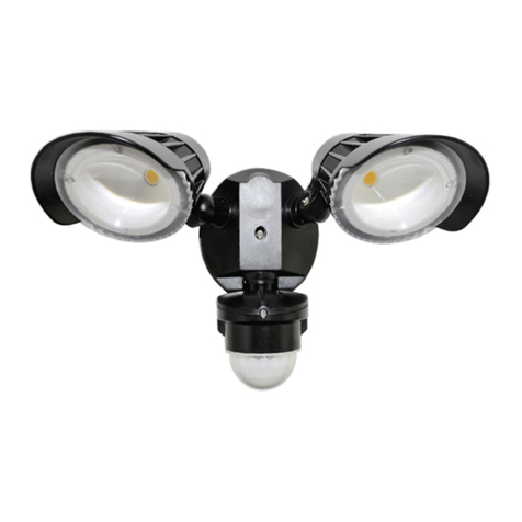
Raytec VARIO2 series User manual

Installation Guide
LITE
VARIO2 i2VARIO2 w2VARIO2 i4VARIO2 w4VARIO2 i6VARIO2 i8VARIO2 w8VARIO2 i16VARIO2 w16
0330-D-00020-1
Contents
Page 1-2 Box Contents and Safety Information
Page 2 Installation Steps
Page 3 Factory Defaults; Complete Set up and Installation
Page 5 Standard Bracketry
Page 6 Specications Table
Page 7-8 Troubleshooting
Box Contents
VARIO2 LITE Illuminator, spare 60° beam angles ILS
(ILS: Interchangeable Lens System)
Accessories (Optional): 80˚ beam and 120˚ beam angle ILS; Bracketry
VARIO2 Enhancements
• Increased Distance
2

2raytecled.com Raytec Global Tel: +44 (0) 1670 520055
Americas Tel: +1 613 270 9990
Eye Safety : IR Variants (850nm and 940nm)
Caution – EN62471 Risk Group 2 Classication - IR emitted from this product.
Do not stare at the lamp. Avoid exposure or use appropriate shielding / eye
protection. For VAR2-LTE-i2-1, VAR2-LTE-i4-1, VAR2-LTE-i6-1, VAR2-LTE-i8-1
and VAR2-LTE-i2-2, VAR2-LTE-i4-2, VAR2-LTE-i6-2 variants hazard distance is
1900mm (Risk Group 1 distance 800mm). For VAR2-LTE-i16-1 and VAR2-LTE-i4-3,
VAR2-LTE-i6-3, VAR2-LTE-i8-2/-3 variants hazard distance is 2700mm (Risk Group
1 distance 900mm).
Eye Safety : White Light and 730nm variants
Caution – EN62471 Risk Group 2 Classication - Possible hazardous optical
radiation emitted from this product. May be harmful to eyes, do not stare at the
lamp. For VAR2-LTE-w2-1, VAR2-LTE-w4-1, VAR2-LTE-w8-1 and VAR2-LTE-w2-2,
VAR2-LTE-w4-2 variants hazard distance is 1500mm. For VAR2-LTE-w16-1 and
VAR2-LTE-w4-3, VAR2-LTE-w8-2/-3 variants hazard distance is 1840mm.
Eye Safety: Other Wavelengths - Contact Raytec.
The Illuminator is Class lll for insulation
Illuminators are suitable for use Outdoors and Indoors
Safety Information
Installation Steps
1. VARIO2 LITE is factory set and delivered with a 35˚ beam width.
To alter to 10˚, simply remove interchangeable lens (ILS).
See page 3 for detailed instructions
To alter to 60˚, replace with other ILS lens supplied
2. Mount Illuminator
3. Connect Illuminator to low voltage input 12-24V AC/DC
(For Vario 16 variants: 24V AC or DC only)
4. Complete conguration - Telemetry Input
Cable
Breather
Gland
Wiring - six core cable
Orange & Purple wires = Telemetry input Volt free/dry
contact or TTL input (See Page 4 for more details)
White & Yellow wires = Photocell following contact.
Volt free output. Non polarity sensitive.
DC AC
Black wire - ~
Red wire + ~
The external cable cannot be replaced. If it is damaged and the customer is unable to
shorten and re-use the cable, the illuminator must not be powered.
3raytecled.com
Raytec Global Tel: +44 (0) 1670 520055
Americas Tel: +1 613 270 9990
Factory Default Set-Up
35˚ Beam Angle ; 100% Power Only
Telemetry Input – closed ; Photocell sensitivity - MID
VARIO2 Lite Complete Set up and Installation
Step 1. Select different beam angle – if required
VARIO is factory set and delivered with a 35˚ beam width angle.
To alter to 10˚, simply remove interchangeable lens (ILS).
To alter to 60˚, replace with other ILS lens supplied.
Other angle ILS lenses are available to order: 80˚ and 120˚.
All ILS lenses will be clearly marked with the angle which they will produce when inserted
into VARIO2.
Please handle ILS lenses with care – and do not touch optical lm.
Only 1 ILS lens can be inserted into the product at anytime. The product cannot
accommodate multiple ILS lenses at the same time.
We would recommend that power is turned off when replacing ILS lenses.
Remove base plate from VARIO2 unit using 2.5mm allen/hex key. Insert required ILS lens
and re-attach base plate securely ensuring gasket is correctly located. (Screw Torque
0.6Nm)
IMPORTANT NOTE: Ensure base plate is securely located, the gasket is correctly
located and the screws correctly fastened to ensure and maintain IP66 rating of the
product.

4raytecled.com Raytec Global Tel: +44 (0) 1670 520055
Americas Tel: +1 613 270 9990
Step 2. Mounting Illuminator
VARIO2 is delivered as standard with bracket at the bottom of the unit. This can be moved
to the top of the unit if required. See page 6 for optional brackets.
Step 3. Connect to low voltage power supply and input 12-24 AC/DC (24 AC/DC only for
Vario 16 Variants)
Step 4. Telemetry Input (Orange & Purple)
As default the telemetry input will be wired together so that the unit turns on/off automatically
via the photocell. If required to be activated by PIR or alarm system, connect to appropriate,
volt-free or TTL input. Volt free input/dry contact: Non polarity sensitive, short circuit = light
on
TTL input: Orange = TTL +ve, Purple = TTL –ve (GND) 0V = Light on, 3V = Light off
Step 5. Photocell following output (White & Yellow)
Volt free output - normally open (day) to normally closed (night). Connect direct to camera
if required to control switch over of day/night cameras.
AB C
Mount and position
illuminator adjacent to
camera and point towards
scene (Optional night set-up for
optimum image performance)
Adjust vertical position of
lamp to ensure full eld of
view illuminated
Tighten all xings
TARGET
A
B
Connect Illuminator to low voltage power supply:
Installers can extend or reduce lead length using
appropriate cable and weather proof box
Input 12-24V AC/DC
(For Vario 16 variants : 24V AC or DC only)
Note: Red = positive
Black = negative

5raytecled.com
Raytec Global Tel: +44 (0) 1670 520055
Americas Tel: +1 613 270 9990
Standard Bracketry
Supplied with the Product (Model Dependant)
(not to scale, dimensions rounded to nearest mm)
VARIO 2 series
51mm
47mm
52mm
VARIO 4/6 series
53mm
72mm
56mm
VARIO 8 series VARIO 16 series
53mm
80mm
104mm
148.5mm
53mm
75mm
Step 6. Photocell adjust.
The photocell can be adjusted by a potentiometer accessed by removing the baseplate.
The default for the photocell is 15 Lux on 30 Lux off. When the pot is turned fully anti
clockwise the levels are 7 Lux on 15 Lux off.
Turning the pot clockwise will increase the light levels that the lamp operates and disables
the photocell. The maximum level before the photocell is disable is approximately 70 Lux
on 160 off.
Photocell
adjust pot

6raytecled.com Raytec Global Tel: +44 (0) 1670 520055
Americas Tel: +1 613 270 9990
i16 w16 i8 w8 i6 i4 w4 i2 w2
10° 500m
(1640ft)
250m
(820ft)
350m
(1148ft)
180m
(591ft)
200m
(656ft)
144m
(472ft)
110m
(361ft)
78m
(256ft)
60m
(197ft)
35° 250m
(820ft)
125m
(410ft)
165m
(541ft)
95m
(312ft)
120m
(394ft)
78m
(256ft)
65m
(213ft)
54m
(177ft)
40m
(131ft)
60° 135m
(443ft)
70m
(230ft)
95m
(311ft)
50m
(164ft)
70m
(230ft)
54m
(177ft)
35m
(115ft)
36m
(118ft)
25m
(82ft)
80° 105m
(344ft)
48m
(157ft)
70m
(230ft)
35m
(115ft)
50m
(164ft)
36m
(118ft)
25m
(82ft)
24m
(79ft)
20m
(66ft)
120° 65m
(213ft)
35m
(115ft)
45m
(148ft)
25m
(82ft)
30m
(98ft)
24m
(79ft)
18m
(59ft)
18m
(59ft)
12m
(39ft)
Consumption 100W max 84W max 46W max 42W max 25W max 13W max 24W max 10W max 11W max
Input 24V AC/DC 12-24V AC/DC 12-24V AC/DC 12-24V AC/DC
Weight 3.1kg (6.8lbs) 1.65kg (3.61lbs) 950g (2.1lbs) 600g (1.3lbs)
Number of LEDs 48 24 12 9 12 6 6
Environment IP66 IP66 IP66 IP66
Dimensions 180 x 277 x 75mm
(7”x11”x2.9”)
135 x 180 x 68mm
(5”x7”x3”)
100 x 135 x 66m
(4”x5”x2.5”)
75 x 100 x 64mm
(3”x4”x2.5”)
Cable Length 2.5m 2.5m 2.5m 2.5m 2.5m 2.5m 2.5m 2.5m 2.5m
VARIO2 Specications Table
Infra-Red Series & White-Light Series
• For i16; w16; i8; w8 the supply to the units should be limited to/ fused at 5A
• For i6; w4 the supply to the units should be limited to/ fused at 3.15A
• For i4; i2; w2 the supply to the units should be limited to/ fused at 1.6A
For IR940nm Distances / Information contact Raytec
Optional Bracketry (not to scale - other Bracketry also available)
Wall Mount
VUB-Pole
Dome Mount
VUB-Plate
(Various Sizes)
Ptz Mount
VUB-Wall
Pole Mount
VUB-PSU Plate

7raytecled.com
Raytec Global Tel: +44 (0) 1670 520055
Americas Tel: +1 613 270 9990
VARIO2 LITE Troubleshoot
Ensure all tests are undertaken by a qualied, trained engineer. Ensure safe working
practices are followed at all times.
Step 1: Basics
• Check polarity of illuminator connection red=+ve, black=-ve
• Ensure power is 12-24V AC or DC (For Vario 16 variants : 24V AC or DC only)
• Ensure telemetry wires are shorted out or valid telemetry input (zero volt or TTL) is
applied and correctly wired
• Ensure power supply is suitably rated to product - check specications table
• If longer cables used, ensure sufcient voltage is provided to allow for drops across
the cable
If Ok...
Step 2: Illuminator Test
• Check current is being drawn – amount of current will depend on power setting of
unit. Please note – use appropriate multimeter depending on how the unit is being
powered (AC or DC)
• To test this you must ensure telemetry wires are shorted out or valid telemetry input
(zero volt or TTL) is applied and correctly wired
Step 3: Set up camera, lens, and illumination
• Check model number to Raytec performance specication to ensure required
distance is achievable;
• Check orientation of unit and ensure it is pointing in correct direction
• Check angle of unit (Interchangeable lens) – Too narrow may cause hot spots and
the aperture of the camera lens to close down. Too wide and there may be insufcient
light on scene and light going where it is not needed.
Step 4: Call Raytec for further assistance
Note Down:
• Model and serial number of illuminator
• Camera make and model
• Camera Lens make and model

Raytec Global (excluding Americas)
Tel: +44 (0) 1670 520055
Raytec Ltd.
Unit 15 Wansbeck Business Park, Rotary Parkway
Ashington, Northumberland, NE63 8QW, United Kingdom
Raytec Americas
Tel: +1 613 270 9990
Raytec Systems Inc.
800-300 Terry Fox Drive, Ottawa, Ontario
2K 0E3, Canada
raytecled.com
If the Raytec illuminator or remote control is still not delivering the required performance,
please contact us for further assistance:
UK / Europe Tel: +44 (0) 1670 520055
Americas Tel: +1 613 270 9990
(Note: The light source (LEDs) of this Illuminator is not replaceable. When the unit reaches
its end of life the whole Illuminator shall be disposed of and re-cycled where possible.)
Raytec Warranty
All Raytec luminaires are provided with an industry leading 5 year warranty and have an
expected useful life in excess of 10 years.
Contact Raytec for more details.
Other manuals for VARIO2 series
4
This manual suits for next models
9
Table of contents
Other Raytec Floodlight manuals

Raytec
Raytec SPARTAN MP Series User manual

Raytec
Raytec Spartan Series User manual

Raytec
Raytec Spartan Series User manual

Raytec
Raytec Raymax 25 PoE series User manual

Raytec
Raytec WARRIOR 24 User manual

Raytec
Raytec SPARTAN SPX Series User manual

Raytec
Raytec SPARTAN SPX-HP15K User manual

Raytec
Raytec Spartan Series User manual