Raytec Ltd reserve the right to change specifications without prior notification or public announcement.
Version 1
www.raytecled.com
1277-D-0002
SPI-AR
Installation Steps
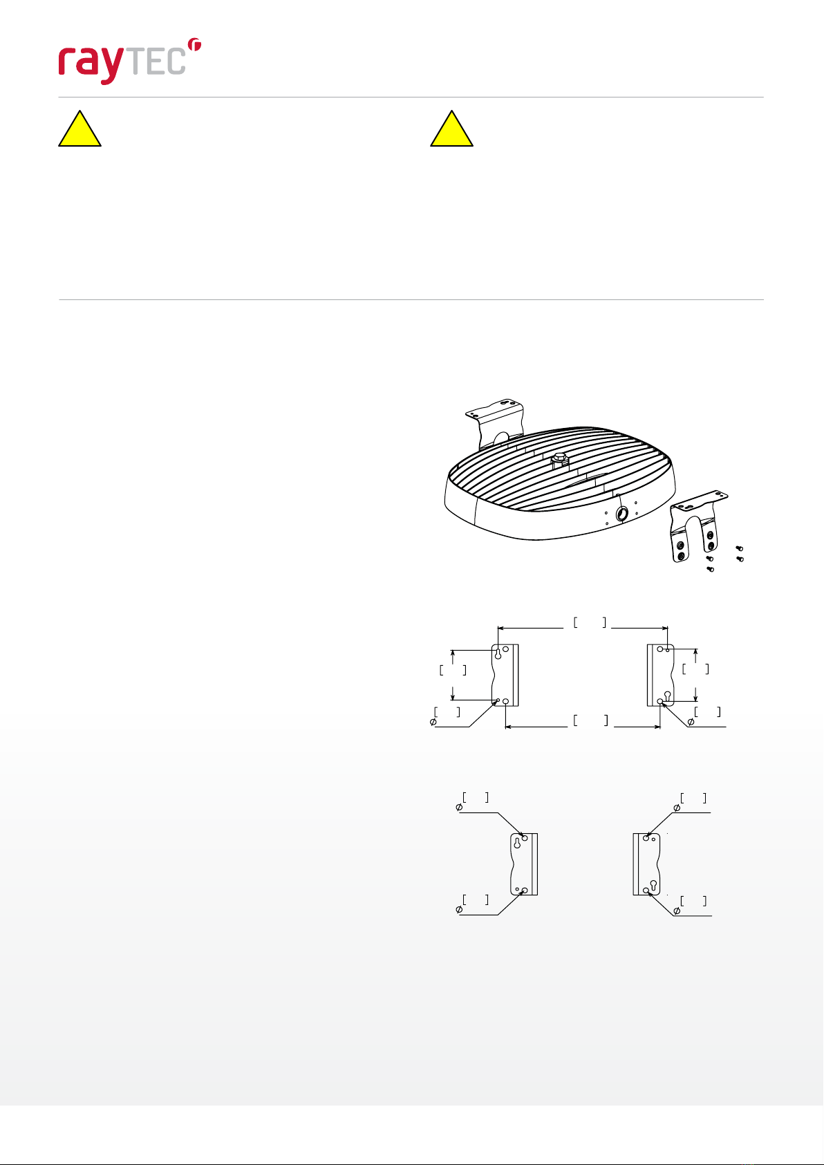
High Vibration Yoke Installation (Ordered Separately)
Step 1.
Step 2.
Step 5.
Step 6.
Step 3.
Step 4.
This SPX-BKT-AR-YK kit is intended for use with UL Listed AR luminaire as marked on the luminaire nameplate.
Accessory Package Contents
Refer to alternate instructions if using Conduit, Hook, Pole, Wall Mount, or Yoke Mount
Inspect shipping package and contents to ensure no damage has occurred during
shipping. Discard surface/ceiling mounting bracket provided with AR luminaire.
Remove 8 x M6 hex bolts from sides of luminaire and discard.
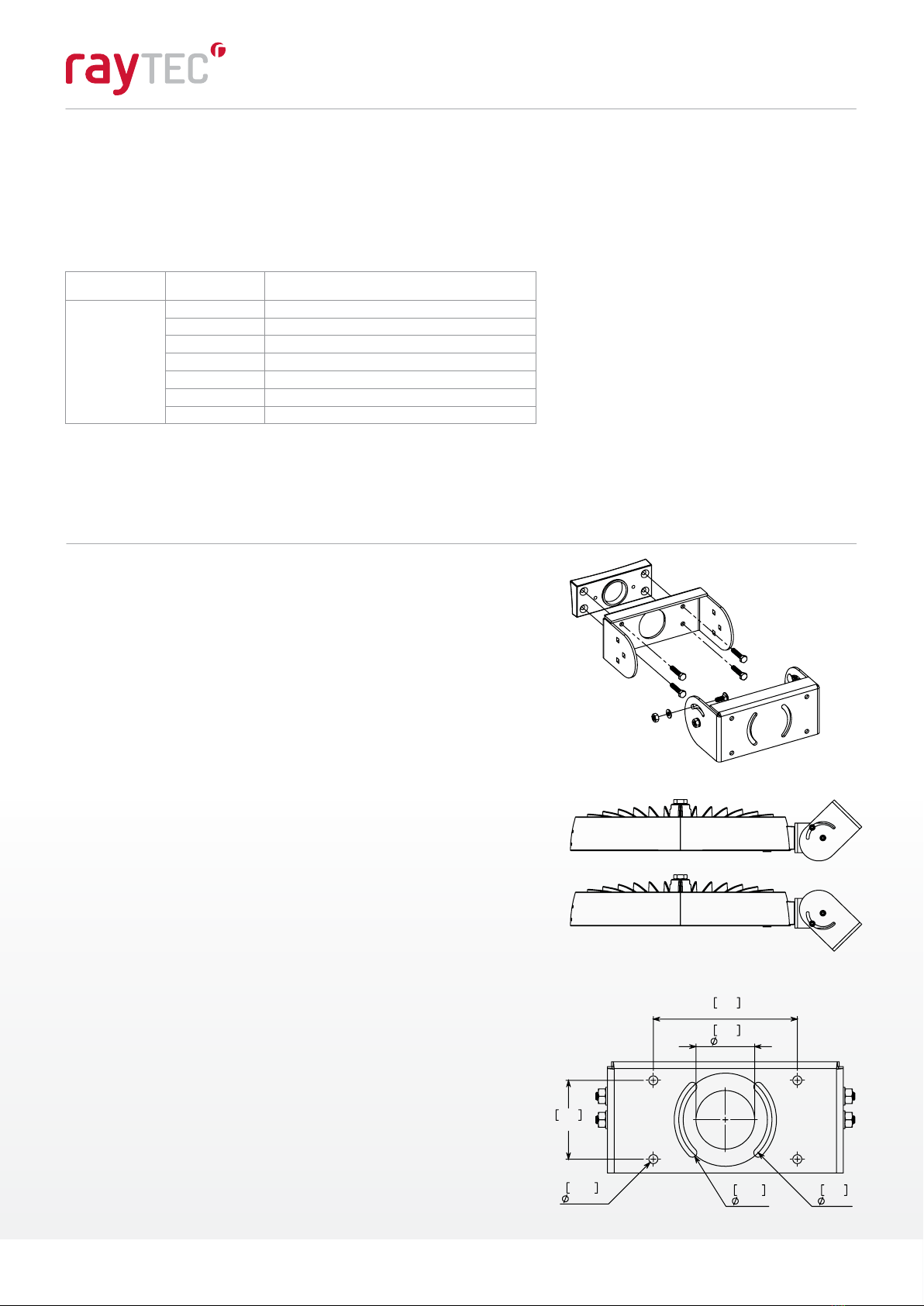
Mount AR high vibration yoke to mounting surface using a minimum of 4x ¼-20 or M6
fasteners (not provided).
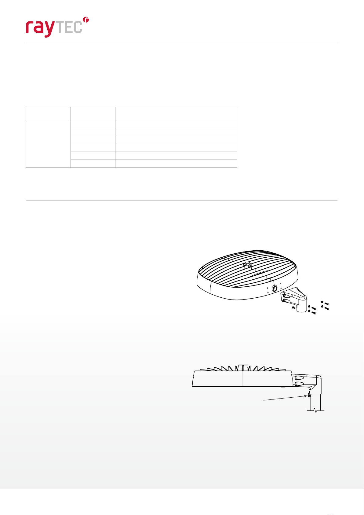
Thread installed wiring through opening in AR high vibration yoke mount and install AR
luminaire into yoke. The raised circular bosses on the AR cheek plates should register
inside of the large circular holes on the AR high vibration yoke mount arms. Rotate
luminaire to aim in the desired direction and fasten in place using 2x M6 socket head
cap screws and at washers per side. Torque fasteners to 5 Nm (45 in-lbs).
Resume installation instructions provided with luminaire. (STEP 4 in AR Installation
Instructions provided with Luminaire)
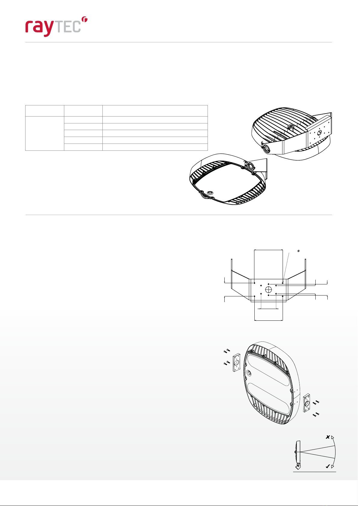
WARNING:
The AR Head must not face
upwards by any degree beyond
the vertical position for Class II,
Division 2, Zone 22, and Class III
hazardous locations.
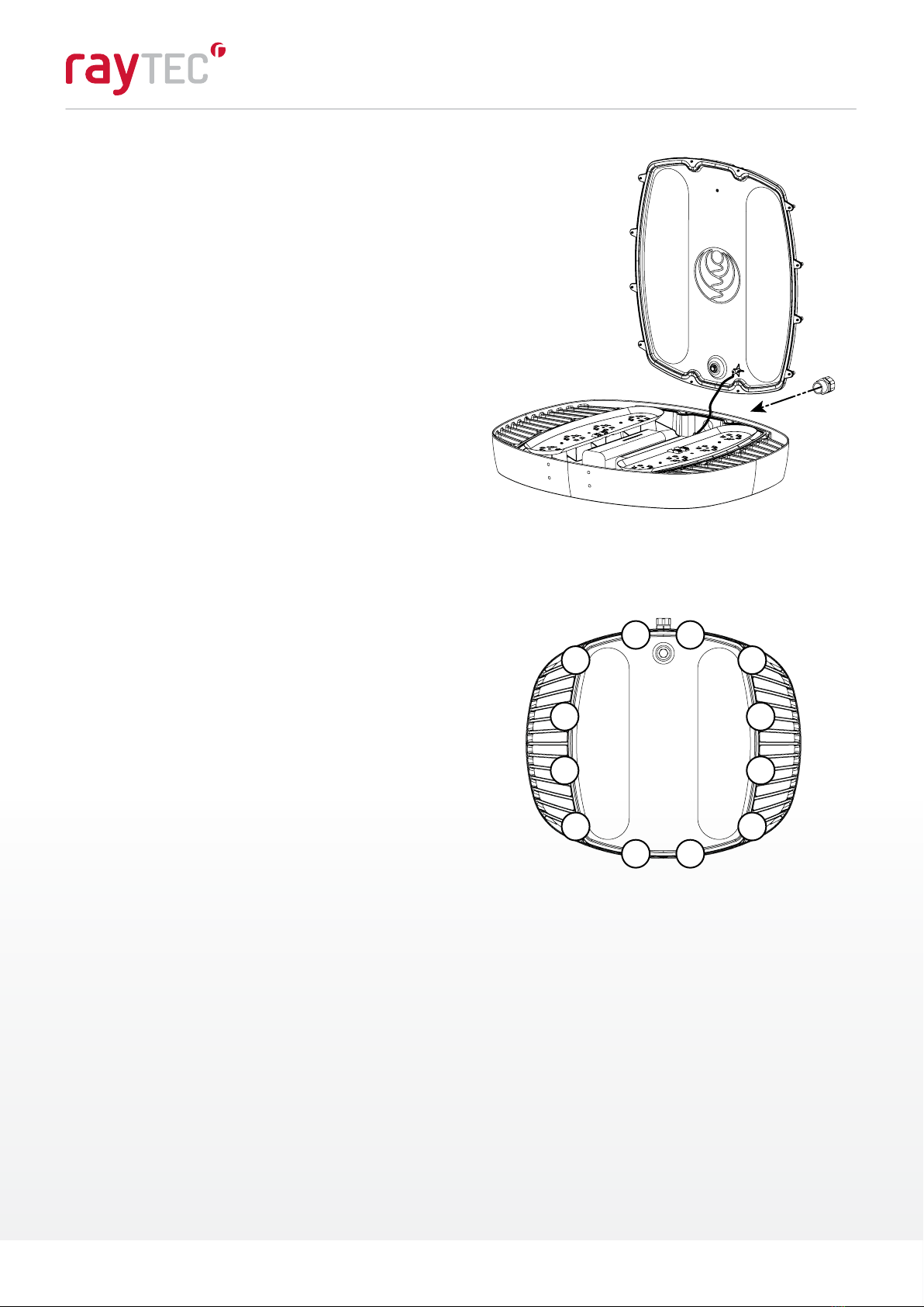
Install suitable wiring system to the conduit opening per CEC/NEC requirements
for the specic location of install.
NOTE: To aid in assembly and protection against ingress use of a petrolatum or
soap thickened mineral oil based thread lubricant/sealant is necessary.
Un-used conduit opening must be plugged to maintain the integrity of the
enclosure.
Mount AR Cheek Plates to sides of AR luminaire using 4x M6 at head cap screws
per side. Thread one cheek plate over installed wiring during assembly. Torque
fasteners to 5 Nm (45 in-lbs).
SPX-BKT-AR-YK QTY PART NAME
1AR HIGH VIBRATION YOKE
2CHEEK PLATE
8M6 x 1 x 25mm SOCKET FLAT HEAD CAP SCREW
4M6 FLAT WASHER
4M6 x 1 x 16mm SOCKET HEAD CAP SCREW
Step 2
Step 4
8.0in
3.8in
203mm
95mm
2.3in 3.1in
59mm
4.3in
80mm
8.0in
108mm
203mm
0.3in
10x
6.8mm
THRUALL
LIGHTBEAM
HORIZON