Raytools BM114 Series User manual

BM114 SERIES
6KW Auto-Focusing Laser Cutting Heads User Manual
Hotline: 400-670-1510
Fax: (021)6760-1511
Email: sales@empower.cn
Add: No.72, Lane 1500, Xinfei Road, Songjiang District, Shanghai

V1.1 Shanghai Empower Technologies Co., Ltd. © Copy Right
www.empower.cn
BM114 SERIES 6KW Laser Cutting Head User Manual
1 | 11
Historical Version:
History
version
Date
Change the profile
Editors
Reviewers
Review date
V1.0
2018/03/01
Establish BM111 User Manual
51 translation
2018/03/01
Alex Li
Thank you for your choosing our product!
This manual makes a detail introduction about the use of BM114 laser cutting head, including
installation, setup, operation and service etc. Please directly contact us if you have other things to
know.
Please read these instructions carefully before use the series cutting head and relative equips.
This will help you to use it better.
Because the product keeps renewing, please note the product you receive may differ slightly
from the illustrations in this manual in some aspects. We apologize for your inconvenience here.
Version
V1.0
Date:
2018/03/01

V1.1 Shanghai Empower Technologies Co., Ltd. © Copy Right
www.empower.cn
BM114 SERIES 6KW Laser Cutting Head User Manual
2 | 11
Index
1 Summary......................................................................................................................................4
1.1 Product Advantages................................................................................................................. 4
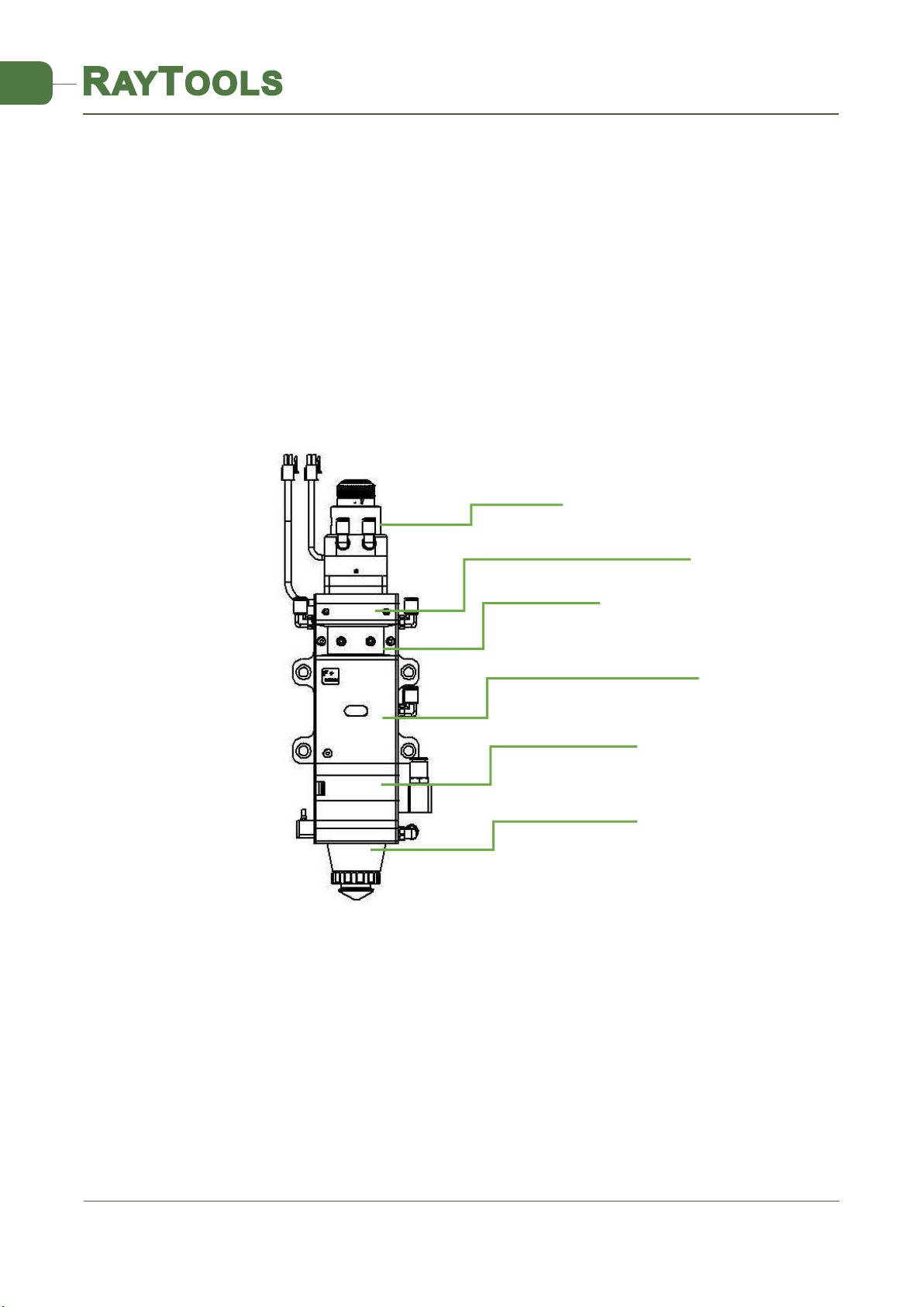
1.2 Structure & Function................................................................................................................ 5
2 Machinery Installation.................................................................................................................6
2.1 Hole site installation installation.............................................................................................. 6
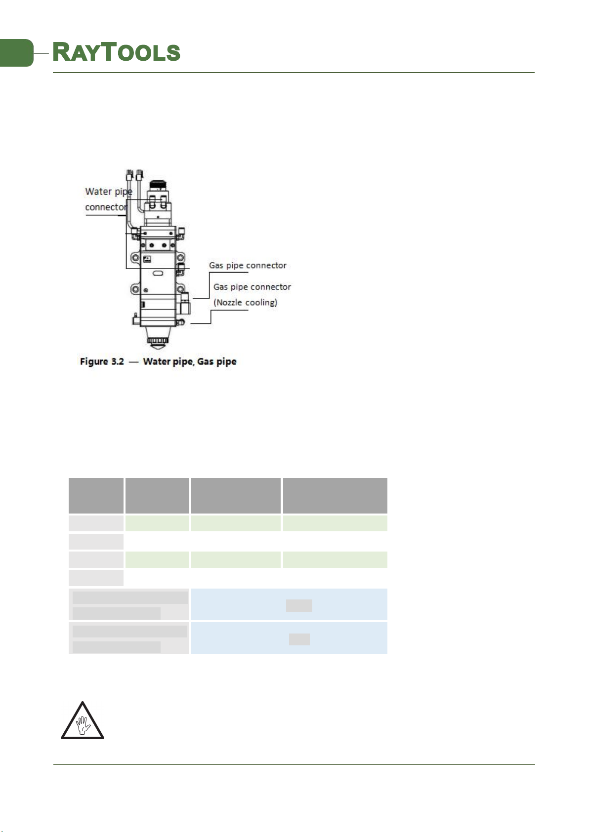
2.2 Connection of Water Pipe and Gas Pipe.................................................................................. 6
2.2.1 Water-cooled interface..........................................................................................6
2.2.2 Assist gas interface................................................................................................ 7
2.3 Connection of Cutting Head Cable........................................................................................... 8
2.3.1 Connection of Cutting Head and Cable................................................................. 8
2.3.2 Cable Connection and Driver Connection............................................................. 8
2.4 Fiber Input Interface.................................................................................................................8
2.5 Fiber Insertion and Interface Direction Adjustment................................................................ 9
3 System Installation Commissioning...........................................................................................10
3.1 EtherCAT Installation.............................................................................................................. 10
3.1.1 Distribution..........................................................................................................10
3.1.2 Configure the Hardware...................................................................................... 10
3.1.3 eInterface Settings and Adjustments.................................................................. 11
3.1.4 Cutting Parameter Setting................................................................................... 13
3.2 BC with position mode........................................................................................................... 14
3.2.1 Distribution..........................................................................................................14
3.2.2 Software Settings.................................................................................................14
3.2.3 Interface Operation............................................................................................. 15
3.3 BC with velocity mode............................................................................................................16
3.3.1 Distribution..........................................................................................................16
3.3.2 Software settings.................................................................................................16
3.3.3 Interface Operation............................................................................................. 17
4 Beam Adjustments and Focusing.............................................................................................. 18
4.1 Beam Adjustments (QBH interface)....................................................................................... 18
4.2 The Focus Position Adjustment..............................................................................................19
5 Maintenance..............................................................................................................................19
5.1 Cleaning Lens..........................................................................................................................19
5.2 Removal and Installation of Lenses........................................................................................20
5.2.1 Removal and Installation of Collimating Protective Lenses................................ 20
5.2.2 Removal and Installation of Collimating Lenses..................................................20
5.2.3 Removal and Installation of Collimating Lenses..................................................21
5.2.4 Removal and Installation of Focus Lenses...........................................................22
5.3 Replace Nozzle Connector......................................................................................................23

V1.1 Shanghai Empower Technologies Co., Ltd. © Copy Right
www.empower.cn
BM114 SERIES 6KW Laser Cutting Head User Manual
3 | 11
5.3.1 Replace Ceramic Body......................................................................................... 23
5.3.2 Replace Nozzle.....................................................................................................24
5.4 Troubleshooting of Driver...................................................................................................... 24
5.4.1 Fault Analysis of AheadTechs Driver....................................................................24
6 BM114 System Constitution......................................................................................................26
6.1 System Constitution (Bus)...................................................................................................... 26
6.2 System Constitution (Non-bus position loop -BC)..................................................................27
6.3 System Constitution (Non-bus position loop -BC)..................................................................28
7 Mechanical and Optical Configurations Diagram......................................................................30
7.1 Cutting Head Shape................................................................................................................30
7.1.1 Focus length.........................................................................................................32

V1.1 Shanghai Empower Technologies Co., Ltd. © Copy Right
www.empower.cn
BM114 SERIES 6KW Laser Cutting Head User Manual
4 | 11
1 Summary
This manual covers the general description of BM114 series products, including the basic installation, factory
settings, operation, use and maintenance services and other aspects. The specific Optical mechanical
customization configurations are too much, so only the main unit parts will be introduced in this manual.
The BM114 series is an automatic focusing fiber cutting head released by Swiss RAYTOOLS AG in 2016. The
product is equipped with external servo motor and internal driver units, which can drive the focus lamp to change
position automatically in the range of about 25mm by linear mechanism. Users can continuously focus through
setting program to finish the rapid perforation of thick plates and the automatic cutting of plates of varies
thickness and material. The product can be equipped with D37 composite lens group to integrate the beam, a
variety of interface settings, so that it can be used with a variety of fiber lasers; optimized optical and
water-cooled design allows the laser head work under high power steadily for a long time.
1.1 Product Advantages
Optimized optical configuration and smooth and efficient airflow design;
Automatic focusing range + 10 ~ -15mm, adjustment accuracy 0.05mm;
Equipped with D37 composite lens, the maximum fiber input power can carry 6KW;
Maximum acceleration of focus lens driver 10m / s2, maximum speed 10m / min;
The drawer type lens holder make the replacement of protective lens more quickly and easier
The composite lenses were used for collimation and focusing to obtain the best optical quality and cutting
QBH interface
Collimating module
Base module with focusing system
Protective lens module
Cutting nozzle module
Collimating protective lens module
Fig 1 - laser head structure

V1.1 Shanghai Empower Technologies Co., Ltd. © Copy Right
www.empower.cn
BM114 SERIES 6KW Laser Cutting Head User Manual
5 | 11
effect;
Equipped with QBH, QD and other fiber interfaces can match with various fiber lasers.
1.2 Structure & Function
As shown in Figure 1, the laser head consists of four basic units, such as collimating
module CM, focusing driving module, protective lens module and nozzle module.
Collimating module: The collimation function of the optical fiber is collimated after the
incident laser is collimated into a parallel beam and the function of tuning;
Focusing driving module: The collimated beam is focused into a concentrator beam with high power
density, and the focus position is automatically adjusted by the driving device;
Protective lens module: the protective lens protects the focusing lens from damage by returning the slag
and prolongs the service life of the focusing lens;
Nozzle module: Guide the focus beam to the work piece and produce high velocity jet cutting to achieve
high quality cutting

V1.1 Shanghai Empower Technologies Co., Ltd. © Copy Right
www.empower.cn
BM114 SERIES 6KW Laser Cutting Head User Manual
6 | 11
2 Machinery Installation
2.1 Hole site installation installation
BM114 laser machining head and the fixed mounting hole size and position of the machine tool are shown in
Figure 3.1. Customers are advised to Install the laser head perpendicular to the machined surface as requested
and make sure the laser head is locked, which is one of the premises to ensure the follow up sable cutting effect.
CAUTION: the Z-axis sliding base for fixing laser processing head should be connected with machine tools
and keep a good grounded.
2.2 Connection of Water Pipe and Gas Pipe
2.2.1 Water-cooled interface
BM114 laser processing head has 3 sets of water-cooled channels which direction of water entry and exit can
be arranged arbitrarily. It is important to note that when the laser power is greater than 500 watt hours, it is
recommended to use water-cooled.as you can see from Figure 3.2, the position and amount of the water
interface, and the right table details the recommended flow velocity.
The design of this water-cooled interface is closed loop water-cooled system, and it also can be used
equipped with external water supplied but subjected to the requirements of the list.
Outer diameter of water pipe
caliber
6mm
Minimum flow speed
1.8 l/min(0.48gpm)
Entry pressure
170-520kPa(30-60 psi)
Entry temperature
≥room tempreture />dew point
Hardness (relative to CaCO3)
<250mg/liter
PH range
6 to 8
Particles size available
Diameter less than 200 microns
Figure 3.1 — Hole site installation

V1.1 Shanghai Empower Technologies Co., Ltd. © Copy Right
www.empower.cn
BM114 SERIES 6KW Laser Cutting Head User Manual
7 | 11
2.2.2 Assist gas interface
The impurity in auxiliary gas such as hydrocarbon and steam will damage the lens and cause cutting power
fluctuation as well as inconsistencies between the sections of the work piece. The firm below is the recommended
auxiliary gas specification. The higher the purity of the gas, the better the quality of the cutting section.
Impurity can be filtered out in gas supply tube, but Oxygen and water vapor can permeate light path through
nonmetal materials, which is the source of the appearance of dust and hydrocarbon. Stainless steel fittings are
recommended, at the same time must use filters which can remove a minimum of 0.01 micron particle to purify.
A pressure gauge with a stainless steel diaphragm is recommended. Industrial pressure gauges suck in air.
Rubber diaphragm produce hydrocarbon by aging or other factors.
CAUTION: Gas interface can not be replaced arbitrarily, especially do not use PTFE TAPE, Otherwise,
the gas path will be blocked, the normal cutting will not be possible and the laser head parts will be
damaged at the same time.
Gas
Purity
Maximum content
of water vapor
Maximum content of
hydrocarbon
oxygen
99.95%
<5 ppm
<1 ppm
nitrogen
99.99%
<5 ppm
<1 ppm
argon
99.998%
<5 ppm
<1 ppm
helium
99.998%
<5 ppm
<1 ppm
Diameter of auxiliary gas
pipe (Outer diameter)
10mm
Diameter of cooled gas
pipe (Outer diameter)
8mm

V1.1 Shanghai Empower Technologies Co., Ltd. © Copy Right
www.empower.cn
BM114 SERIES 6KW Laser Cutting Head User Manual
8 | 11
2.3 Connection of Cutting Head Cable
This paper mainly introduces the connection between the cable and the cutting head. The control section of
the driver and the connection refer to the wiring diagram of each series of system.
2.3.1 Connection of Cutting Head and Cable
Connect the corresponding connector of cutting head with motor power cable, encoder cable, sensor cable
respectively (as shown in figure 3.3). After the proper length is reserved, the cable is inserted into the track groove
of the machine tool and fixed.
2.3.2 Cable Connection and Driver Connection
Connect motor power wire and encoder wire with the corresponding interface of driver according to the
definition in cable sleeve. The wiring of the drive and limit sensor cables is shown in the wiring diagram of the
various wiring systems attached. Caution: The limiting sensor is divided into high level output and low level
output, and the two are normally closed output mode(high level and low level signal are output by the sensor
when not triggered); electric relay should be self installed when necessary to carry on the high-low level or the
normally open and normally closed conversion.
CAUTION: All wiring is in the state of power failure, and the power can be debugged after inspection.
2.4 Fiber Input Interface
BM114 is suitable for most industrial laser generators. It is equipped with collimating mirror assembly
The connection between the end of the fiber and the cutting head is called fiber interface. Commonly used
fiber connectors include QBH, QD, etc, and every fiber interface has its unique fixation method. Please refer to
corresponding instruction of fiber interface. Figure 5 shows the installation interface of QBH connector.
WARNING: The optical devices must be kept clean and all dust must be removed before use. If the laser
head is vertically inserted in the optical fiber, the laser head must be rotated 90 degrees to the
horizontal level and then inserted into the optical fiber to prevent dust from entering the interface and
falling on the surface of the lens. Upper limitng in the fiber before fixing the laser head.

V1.1 Shanghai Empower Technologies Co., Ltd. © Copy Right
www.empower.cn
BM114 SERIES 6KW Laser Cutting Head User Manual
9 | 11
2.5 Fiber Insertion and Interface Direction Adjustment
In this paper, an optical fiber insertion method is described in conjunction with a QBH joint.
First, align the red point at the end of the QBH interface with the red point of the handwheel; then remove
QBH dust proof cover and the red mark of fiber output end is aligned QBH red mark and insert straight to
bottom; Then turn the QBH handwheel clockwise. It is in place when you hear the "Da" sound,then pull the
handwheel up and turn clockwise again. (see Figure 3.4)
If when the fiber connector insert into the interface, the red dot on fiber is too far away from the red dot on
laser head interface, causing an out of alignment insertion, when can refer to steps below to adjust the position of
fiber interface on laser head for solving the problem. As shown in Fig. 3.4, unscrew the 4 locking screws of the
position of the part icon with a wrench, rotate the QBH interface and screw the locking screws after the red mark
is in place.

V1.1 Shanghai Empower Technologies Co., Ltd. © Copy Right
www.empower.cn
BM114 SERIES 6KW Laser Cutting Head User Manual
10 | 11
3 System Installation Commissioning
3.1 EtherCAT Installation
3.1.1 Distribution
AheadTechs driver + 30W DC motor:
The motor is DC servo motor, which should connect the end of the drive L1, L2 respectively with+24V
and 0V, and the driver power supply L1C and L2C should connect to 220V exchange L and N.(24V power
supply is customer-owned)
When EtherCAT is in bus model, the driver in TSM must be placed before 150P device, C5 interface is
CAN IN, C6 interface is CAN OUT
Limit signal:
Black
White
Brown
Blue
Lower limit
Upper limit
+24V
0V
Note: the limit sensor is active low, and the signal is often closed, and it continuously outputs 0V
signal when it is not triggered. When the configuration bus scheme is used, it needs to connect the relay and be
switched to active-high output.
The limit diagram is shown in Figure 4-1.
3.1.2 Configure the Hardware
Hardware: bus model driver must be connected before DX-150P. As per: Host - F axis drive - 150P - EIO500 -
EDS88C0 (Figure 4.2), connect the F-axis limit and power cord to the I/O, remember the corresponding pin end

V1.1 Shanghai Empower Technologies Co., Ltd. © Copy Right
www.empower.cn
BM114 SERIES 6KW Laser Cutting Head User Manual
11 | 11
number of upper and lower limit.This pin is defined according to field redundant inputs, or expanded cards) The
lower limit is in the biFNegLimit, and the upper limit is on the biFPosLimit.
Software: first copy xml files in the driver to C:\TwinCAT\Io\EtherCAT (it’s necessary when it’s EtherCAT bus
model driver, if not and use 150P it need not to), run the HMI interface to change the path to the HMI, and in TSM
first let TSM become config mode, and then scan the devic. In the pop-up dialog box, select the new add drive,
and the 150P on the right, Select before, add the drive, select the F axis in the NC axis, and drive the link to the F
axis; In the corresponding card and the corresponding pin, link to PLC in the F axis positive and negative limit field
(lower limit biFNegLimit, upper limit biFPosLimit). Activate TSM, run HMI.
3.1.3 eInterface Settings and Adjustments
After the configuration is completed, enter the home / settings / super administrator login / factory /
function switch / auto focus /F axis, enter the axis parameter /F axis, in the axis parameter, open debugging
"TRUE", after setting up, the CNC interface is shown in Figure 4.3.
Figure 4.3— CNC interface
Figure 4.2 — TSM configuration diagram

V1.1 Shanghai Empower Technologies Co., Ltd. © Copy Right
www.empower.cn
BM114 SERIES 6KW Laser Cutting Head User Manual
12 | 11
1. Verify the servo parameters (the number of pulses per turn, the number of pulses per turn)
2. Inch F axis, check whether the action is normal (from the pitch and direction), 0 scale upward movement
of F+.
3. Slow moving the F axis so that it meets the positive and negative limit, check the signal, the direction is
right (positive and negative limit wiring has pipe sleeve mark)
4. Axis parameter (default parameter, shown in Figure 4.4)
AheadTechs drive bus pulse 10000 pulse / loop
Zoom speed is recommended to set the value to 50-100mm/s
5. F axis zero return, zero focus coke (zero focus position and zero position coincides with the same point)
steps:
1) The parameter point position is set to 0.
2) F axis zero return with barrel moving downward and touches lower limit scale at bout -13 (note:
Upper limit at about +10)
3) View the position on the cutting head. For example, -10.
4) Reset the parameter point position to -10.
5) Return to zero again.
6) Laser dotting confirms whether coke is zero.
7) By manually move the F tuning, find focus position. Record the coordinates at this time. For
Figure 4.3 — CNC Interface

V1.1 Shanghai Empower Technologies Co., Ltd. © Copy Right
www.empower.cn
BM114 SERIES 6KW Laser Cutting Head User Manual
13 | 11
example, -1.
8) Change the parameter point position to -9.
9) Again back to zero, this zero zero position and focal position overlap, change focus finish.
After the zero return, the F axis is moved up and down, so that it touches the limit, records the machine tool
coordinates, and enter coordinates of the upper and lower limits into the positive focus and negative focus of the
F axis.
7.Setting the corresponding soft limit parameter
Note: negative return to zero must be true, reverse wait sync pulse, acceleration, acceleration factor, speed
of change need not be modified, according to the default mode!
3.1.4 Cutting Parameter Setting
When cutting different plates, in the process parameters, fill in different cutting, perforation, focus position
and other parameters (for example, carbon steel, cutting the focus of 1.5, the focus of the perforation is 2, and
other parameters, such as Figure 4.5)
Fig 4.4-Axis parameter interface

V1.1 Shanghai Empower Technologies Co., Ltd. © Copy Right
www.empower.cn
BM114 SERIES 6KW Laser Cutting Head User Manual
14 | 11
3.2 BC with position mode
3.2.1 Distribution
AheadTechs driver + 30W DC motor:
The motor is DC servo motor, which should connect the end of the drive L1, L2 respectively with+24V
and 0V , and the driver power supply L1C and L2C should connect to 220V exchange L and N.(24V power
supply is customer-owned)
Limit signal:
Black
White
Brown
Blue
Lower limit
Upper limit
+24V
0V
Note: the limit sensor is active low, and the signal is often closed, and it continuously outputs 0V signal when it
is not triggered. The limit diagram is shown in Figure 4-1.
3.2.2 Software Settings
Open the platform configuration tool, enter the value shown in Figure 4.6
1. Set parameter as the figure.
Figure 4.5 — Process interface

V1.1 Shanghai Empower Technologies Co., Ltd. © Copy Right
www.empower.cn
BM114 SERIES 6KW Laser Cutting Head User Manual
15 | 11
2. Select J axis for detection, open loop point movement control. Move or detect the encoder in the
(-14mm~+9mm) stroke to determine the encoder direction.
3. Save the parameters and enter the interface
3.2.3 Interface Operation
1. Inch J axi, check up if the action is normal(distance to “pitch” and direction), 0 scale moves up to J+.
2. Slow moving the J axis so that it meets the positive and negative limit, check whether the direction, the
signal is normal or not.
3. Click zero returning icon, J axis move to negative direction and return zero again when touches negative
limit, at the same time ,the position of zero point coincides with zero foal position and the zero returning
is finished.
Figure 4.6 — Platform configuration tools
Figure 4.7— Operation interface

V1.1 Shanghai Empower Technologies Co., Ltd. © Copy Right
www.empower.cn
BM114 SERIES 6KW Laser Cutting Head User Manual
16 | 11
Note:
1. Click+, the barrel move upward. When it touches positive limit, click -, then barrel move downward to
the negative limit.
2. The direction of origin is negative, and take lower limit as a sampling signal.
3. Pitch 2mm, 10000 pulses one turn
4. Positioning speed recommended setting 50-100mm/s.
3.3 BC with velocity mode
3.3.1 Distribution
1. AheadTechs driver + DC motor :
The motor is DC servo motor, which should connect the end of the drive L1, L2 respectively with+24V
and 0V , and the driver power supply L1C and L2C should connect to 220V exchange L and N.(24V power
supply is customer-owned)
2. Limit Signal:
Black
White
Brown
Blue
Lower limit
Upper limit
+24V
0V
Note: the limit sensor is active low, and the signal is often closed, and it continuously outputs 0V signal
when it is not triggered. The limit diagram is shown in Figure 4-1.
3.3.2 Software settings
The axis parameter settings are shown in Figure 4.8.
Entry J axis detection, “closed loop movement control”, inch J axis, detect whether the action is nomal, 0
scale moving upward is J+, encoder and speed detection.

V1.1 Shanghai Empower Technologies Co., Ltd. © Copy Right
www.empower.cn
BM114 SERIES 6KW Laser Cutting Head User Manual
17 | 11
3.3.3 Interface Operation
1. Close to upper limit. Inch J axis after ensure there’s no warning and detect whether the action is
normal(distance to “pitch” and direction), 0 scale moving upward is J+
2. Slow moving J axis so that it touches the positive and negative limit, detect whether the signal and
direction is right.(The positive and negative limit wiring has the pipe sleeve mark)
3. Click zero returning icon, J axis move to negative direction and turn to zero again after touching the
negative limit. At the moment zero point position coincides with zero focus position, the zero returning is
finished.
Figure 4.8— Platform configuration tools
Figure 4.9— Operation interface

V1.1 Shanghai Empower Technologies Co., Ltd. © Copy Right
www.empower.cn
BM114 SERIES 6KW Laser Cutting Head User Manual
18 | 11
Note:
1. Click +, the barrel move upward, click - when it touches negative limit. The barrel move downward and
arrive negative limit.
2. The direction of origin is negative, and take lower limit as a sampling signal.
3. Pitch 2mm, 10000 pulses one turn.
4. Positioning speed recommended setting 50-100mm/s.
4 Beam Adjustments and Focusing
4.1 Beam Adjustments (QBH interface)
Cutting quality in a great extent depend on whether the lens is in the middle. If the lens is not in the middle,
the laser beam may contact with nozzle or inner wall to produce high temperature deformation. Lens centering
operation should be considered when nozzle is replaced or the cutting quality is decreased.
Lens centering of laser cutting head can be finished by adjusting Collimating mirror, X-Y direction. The
adjusting screw is located on the top of the cutting head as shown in Figure 5.1. By using inner hexagon spanner
can loosen or screw the adjusting screw until the beam is located in the middle of nozzle. Make sure the laser
beam output from the center of nozzle. A method commonly used tape dotting method:
Pick a scotch tape, flatten it, and attach it to the center of nozzle which directly below the hole end face;
Open the inner guiding red light of the laser. Find and observe the position of nozzle center that the red light
in the scotch tape relative to;
Next open and adjust laser generator at the range of 80W-100W and dot manually.
Tear off the tape and check the hole in the center of the nozzle;
Repeat the above steps to find the optimum relative nozzle center position of the beam;
This adjustment requires a series of adjustments, which is the basic operation of general laser tuning.

V1.1 Shanghai Empower Technologies Co., Ltd. © Copy Right
www.empower.cn
BM114 SERIES 6KW Laser Cutting Head User Manual
19 | 11
4.2 The Focus Position Adjustment
BM114 is equipped with automated focusing system. But it still need dot manually to redecide the focus position
when it reset of replacement of lenses, lasers. For details about operating system parameters, please refer to the
system instructions.
Manual focus can refer to the following steps:
1. The laser head scale is displayed to the maximum, and the laser power range is set to 80-100w;
2. Then, within each moving 0.5mm (as small as possible), open a laser hole on the textured paper;
3. Drilling several times, finally compare and find out the scale corresponding to the smallest hole is zero
coke, that is, the focus is just at the end of the nozzle section.
5 Maintenance
5.1 Cleaning Lens
It’s necessary to maintain lenses regularly because of the characteristic of laser cutting process. Once a
weak cleaning the protective lenses is recommended. The collimating lenses and focusing lenses are
recommended to clean once every 2~3 months. In order to facilitate the maintenance of the protective lens, the
protective lens holder adopts a drawer type structure. (Figure 6.1)
Lens cleaning
a. Tools: Dust-proof gloves or finger stall, long fiber cotton stick, ethanol, rubber gas blowing.
b. Cleaning instruction:
1. The left thumb and index finger with fingertip;
2. Spray ethanol onto the absorbent cotton stick
3. Hold the slide edge of the lens with left thumb and index finger gently.(note: avoid the fingertip touching
Table of contents
Other Raytools Cutter manuals