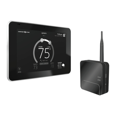
Comfort Sync A3 Assembly instructions

Comfort Sync A3
Ultra Smart Thermostat
Installation and Setup Guide
508026-01 12/2019
Copyright 2019©Allied Air Enterprises, Inc.
West Columbia, SC, USA

2
Table of Contents
Shipping and Packing List........................................................................................3
Operating and Storage Environment, Electrical and Dimensions........................3
Installation Recommendations ................................................................................3
Smart Hub Installation, External Components, LEDs and Terminals...................3
Smart Hub Installation............................................................................................3
Smart Hub External Components ..........................................................................4
Smart Hub Push Button Functions.........................................................................4
Smart Hub LED Indicators .....................................................................................5
Smart Hub Terminals and Wiring Requirements....................................................6
HD Display Installation, External Components and Terminals ............................6
HD Display Attachment ..........................................................................................7
HD Display External Components..........................................................................7
HD Display Terminals.............................................................................................8
Connecting Low Voltage Wiring...............................................................................8
Control Wiring Requirements.................................................................................8
Discharge Air Temperature Sensor (DATS) (Optional for Indoor Unit)...................8
Outdoor Air Temperature Sensor (OATS) .............................................................8
Reducing Electrical Noise on Communication Bus - Indoor, outdoor, HD
Display and Smart Hub. .........................................................................................8
Wiring Diagrams.....................................................................................................9
Electric Heat Conguration for Communicating Air Handlers............................13
Commissioning........................................................................................................13
Commissioning and Service (Using the Mobile Setup Application) .....................13
Mobile Device Operating System Requirements........................................................... 14
Establishing a Direct Wireless Connection to the Smart Hub ....................................... 14
Service .......................................................................................................................... 14
Alternative Method ........................................................................................................ 15
Multiple Smart Hub(s) - Group ID.................................................................................. 15
Restarting Smart Hub.................................................................................................... 15
Commissioning (Using the HD Display)...............................................................15
Boot-up Screen ............................................................................................................. 15
Low Battery Status ........................................................................................................ 15
Dealer Info and Language Selection ............................................................................. 15
Warning Screen............................................................................................................. 15
General Information....................................................................................................... 16
Equipment Found Screen.............................................................................................. 16
Non-Communicating Equipment ................................................................................... 16
Reminders ..................................................................................................................... 16
Comfort Sync Zoning .................................................................................................... 16
Setup Airow Per Zone.................................................................................................. 17
Commissioning Completion........................................................................................... 17
Dealer Control Center .............................................................................................17
Equipment Parameters ........................................................................................18
Tests.....................................................................................................................40
Diagnostics...........................................................................................................40
Installation Report ................................................................................................40
Information ...........................................................................................................40
Dehumidication Settings ......................................................................................41
Dehumidication Setting Options.........................................................................41
Overcooling..........................................................................................................41
Dehumidication Set Point...................................................................................41
Advanced Dehumidication Descriptions.............................................................41
Displaying Outdoor Temperature (Sensor) and Indoor Humidity on the
Home Screen............................................................................................................43
Displaying the Outdoor Sensor Temperature on the Home Screen.....................43
Displaying the Indoor Humidity on the Home Screen ..........................................43
Comfort Sync Zoning .............................................................................................43
Ventilation (ERV, HRV and Fresh Air Damper) ......................................................44
Energy Recovery Ventilator (ERV).......................................................................44
Heat Recovery Ventilator (HRV) ..........................................................................44
Fresh Air Damper.................................................................................................44
Zoning Application ......................................................................................................... 44
Operation of Fresh Air Dampers with Environmental Overrides.................................... 44
Ventilation Control Modes ....................................................................................44
Wi-Fi Connection .....................................................................................................45
Performance Reports..............................................................................................46
Notications.............................................................................................................47
Alert Code Types..................................................................................................47
Service Notication Codes...................................................................................47
Alert Codes ..........................................................................................................47
Electrical Troubleshooting .....................................................................................87
Overview ..............................................................................................................87
Denitions ............................................................................................................87
Testing..................................................................................................................87
Technical Support ...................................................................................................87
Index .........................................................................................................................88

3
Shipping and Packing List
Quantity Description
1Comfort Sync A3 ultra smart thermostat includes a Smart Hub
and HD Display
4 Mounting screws (#6 X 1.25” pan head)
4Wall anchors (alligator anged solid wall anchors)
1 Installation and setup guide
1 User guide
1Warranty certicate
NOTE: Due to Allied Air’s ongoing commitment to quality, features and options
are subject to change without notice and without incurring liability.
Improper installation, adjustment, alteration, service or maintenance
can cause property damage or personal injury. Installation and service
must be performed by a qualied installer and servicing agency.
Operating and Storage Environment, Electrical and Dimensions
• Operating Temperature is 32°F to 104°F (0 to 40°C)
• Shipping and storage temperature range is -4°F to 140°F (-20°C to 60°C)
• Operating humidity range is 10% to 90% non-condensing at 104°F (40°C)
• Storage humidity range is 5% to 95% non-condensing at 104°F (40°C)
• Comfort Sync A3 Smart Hub Power Input: 24VAC, 1AMP at 60Hz.
• Comfort Sync A3 Smart Hub DC Power Output: 12VDC (to HD Display)
• Dimensions (H x W x D):
»HD Display: 7-1/4” x 5” x 1” (184 x 122.5 x 23 mm)
»Comfort Sync A3 Smart Hub: 4-1/2 x 4-/2 x 1-1/2” (114 x 114 x 38 mm) -
antenna length is 7-1/4” (184 mm)
Installation Recommendations
WARNING
Improper installation, adjustment, alteration, ser vice or maintenance can
cause property damage, personal injury or loss of life.
Installation and service must be performed by a li censed professional HVAC
installer (or equivalent) or a service agency.
Before beginning installation, note the type of equipment, number of stages,
and any accessories being installed.
Do
• Read this entire document, noting which procedures pertain to your specic
equipment and system requirements.
• Make sure that all wiring conforms to local and national building and electrical
codes and ordinances.
Do Not
• Install on voltages higher than 30VAC.
• Short (jumper) across terminals on the gas valve or at the system controls
to test installation. This will damage the thermostat and void the warranty.
• Exceed 300 feet (91 meters) run when using 18AWG or 22AWG thermostat
wire or larger (shielded or unshielded).
• Allow power load from any thermostat connection to be more than 1 AMP.
Smart Hub Installation, External Components, LEDs and Terminals
Smart Hub InStallatIon
1. Things to consider when installing the Smart Hub:
• Install near the indoor unit such that there is a direct path to the
approximate location of the home Wi-Fi access point (the signal is not
blocked by the indoor unit or duct work, for example).
• Can be attached to a vertical surface such as a wall stud or roof truss
web, or to a horizontal surface such as a oor or ceiling joist, or a roof
rafter.
• Smart Hub antenna should be positioned such that it is roughly vertical,
no matter the orientation of the Smart Hub itself.
• Do not install the Smart Hub on the indoor unit, duct work, or other
equipment that could induce vibration in the Smart Hub.
• Do not install the Smart Hub on or near large metal objects. This could
adversely affect the range and directional coverage of the Smart Hub
Wi-Fi signal.
• If the Smart Hub MUST be installed on a metal object, orientate the
antenna perpendicular to the metal surface.
• In all cases, the Smart Hub antenna orientation may need to be
adjusted to obtain best Wi-Fi results.
2. Use the procedure outlined in “Figure 1. Smart Hub Installation” on page
4 to install the Smart Hub controller.

4
1/4”
STRIP 1/4” INSULATION FROM
END OF EACH CONTROL WIRE
A
B
D
USE SMART HUB AS TEMPLATE TO MARK DESIRED MOUNTING
LOCATIONS ON WALL OR STUD.
CAUTION: DO NOT OVERTIGHTEN LOWER MOUNTING SCREW, MAY
DAMAGE SMART HUB.
SECURE SMART-HUB TO
WALL WITH
FIELD-PROVIDED
FASTENERS
RAER
TNORF
KEYHOLE
THROUGH-HOLE
C
MAKE CONNECTIONS TO SMART HUB
SCREW TERMINALS USING WIRING
DIAGRAMS PROVIDED
TERMINALS
(screw type)
+
-
COMMBUS
A B
R i+ I- C
ACC1 ACC2
+
-
COMMBUS
A B
R i+ I- C
ACC1 ACC2
Figure 1. Smart Hub Installation
3. For low voltage wiring connections use diagrams in section titled
“Connecting Low Voltage Wiring” on page 8.
IMPORTANT
Do not install smart hub in location were direct exposure to condensation or
dripping water is possible.
Smart Hub ExtErnal ComponEntS
System Status LED
System Commissioning
Status LED
USB Port
Manual Reboot Button
Terminal Connection Access Cover
Antenna
Figure 2. Smart Hub Indicators and External Components
Smart Hub puSH button FunCtIonS
The Smart Hub push button is for rebooting. Press and hold the button for ve
seconds to reboot the Smart Hub.
The push button has a LED associated with it that indicates the status of the
Smart Hub commissioning state (see “Table 1. System Status LED Indicators”).

5
Smart Hub lED InDICatorS
When alarms are present, you may review alarm(s) listed either on the homeowner notication screen or the menu / settings > advanced settings > dealer
control center > notications screen.
Alert codes which require manual clearing can only be done under the dealer control center > notication screen.
Table 1. System Status LED Indicators
System Status LED
System Commissioning
Status LED
Smart Hub
+
-
COMMBUS
A B
R i+ I- C
ACC1 ACC2
System Status LED
LED
Color Status Description
Green System is
normal
A solid green LED indicates no system errors are detected. System
operating as designed.
Red HVAC
Fault System has critical alert which needs attention.
Amber Wi-Fi Error
Blinking amber LED indicates either Wi-Fi is not connected, no Wi-Fi is
within range, or and Wi-Fi hardware error. Could also indicate intermittent
Wi-Fi connection.
Magenta Thermostat
Error
Blinking magenta LED indicates HD display not connected. (see “Table 2.
Communication Error Troubleshooting
(HD Display to Smart Hub)” on page 6)
Cyan HVAC
Error Indoor unit is not connected or unable to communicate.
Commissioning Status LED
Blue System is
normal No mobile device is directly connected using Wi-Fi to the Smart Hub.
Green Blinking green LED indicates the commissioning button has been activated and the Smart
Hub is waiting for a connection with a mobile device.
Green A solid green LED indicates a mobile device is connected to the Smart Hub.
• If multiple errors are present, the system status LED will display each active error for one second on and
one second off and then display the next error if present.
• The system will continue to cycle through all active errors.
• System status errors are displayed in the following priority: HVAC, thermostat and then Wi-Fi.

6
Table 2. Communication Error Troubleshooting
(HD Display to Smart Hub)
Possible Connection Issues Comfort Sync A3 Smart
Hub - System Status LED
One communication wire at the Smart
Hub COMM BUS A or B terminals is
disconnected.
Flashing Magenta LED
Both communication wires – at
the Smart Hub COMM BUS A or B
terminals are reversed.
Flashing Magenta LED
Power wires at Smart Hub 12VDC +
and - terminals are disconnected. Flashing Magenta LED
If terminals are connected correctly,
then check HD Display mounting to
subbase. HD Display may not be
secured correctly to subbase.
Flashing Magenta LED.
HD Display screen may be
either blank or a message
indicating Comfort Sync A3
cannot communicate with the
equipment.
Smart Hub tErmInalS anD WIrIng rEquIrEmEntS
Table 3. Smart Hub Terminal Designations, Order and Wiring
Requirements
Terminal
Designation Description Thermostat Wiring
R24VAC input 18AWG unshielded
I+ RS-BUS I+ 22AWG shielded
(recommended)
(2-pair conductor only)
I- RS-BUS I-
C24VAC return 18AWG unshielded
ACC1 Accessory 1 and 2 (typically
can be used for 1 or 2
speed ventilators and fresh
air dampers)
18AWG unshielded
ACC2
12+ 12VDC output 18AWG unshielded
ACommunications bus A 22AWG shielded
(recommended)
(2-pair conductor only)
BCommunications bus B
12- 12VDC return 18AWG unshielded
IMPORTANT
Use 2-pair, 18AWG unshielded thermostat cable (eld-provided) for power
terminals (R, C, 12+ AND 12-). Recommend using 2-pair 22AWG shielded
thermostat cable for communications terminals (I+, I-, A and B) which will
help eliminate any noise interference.
HD Display Installation, External Components and Terminals
Use the following procedure for installation of the subbase where existing
thermostat wiring does not exist:
1. Unpack the HD Display and subbase.
2. Determine the best location to install either the subbase. Ideal location
should be located away from outside wall, direct sunlight or discharge air
vents.
3. Cut or drill a small hole for thermostat wiring.
3/8” (10 mm)
Diameter Hole
4. Pull about three inches (75mm) of thermostat wire through the opening
and remove the outer thermostat wire jacket.
Seal wire hole in wall to prevent
cold or hot air from affecting temperature
sensor in display.
IMPORTANT
Seal wire hole in wall to prevent cold or hot air from affecting temperature
sensor in HD Display.
5. Strip 1/4” (6 mm) insulation from end of each wire.
1/4”

7
6. Use a level to align either the subbase on wall horizontally.
7. Use the subbase as a template to mark the desired mounting hole locations
on the wall.
Use the subbase as a template to
mark the desired mounting hole
locations on the wall.
HD Display Subbase
(Rear View)
8. Drill 3/16” (5 mm) holes at marked locations on the wall for anchors. Then
insert wall anchors into holes until ush with the wall.
Drill Holes Insert in hole until flush with wall.
WARNING
DO NOT over-tighten mounting screws. Doing so my distort the subbase
plastic housing and cause connection issues when attaching the HD display.
9. Secure subbase with provided #6 x 1.25” pan-head screws (4).
10. Connect thermostat wiring to subbase screw terminals referencing
provided wiring diagrams in this guide.
HD DISplay attaCHmEnt
1. Hold the HD Display by the edges, line it up with the subbase (horizontal
position), and move the HD Display toward the subbase.
2. Center the cavity on the back of the display over the subbase.
3. Gently press on the edges of the HD Display until you hear the mounting
snaps engage. Be careful not to apply force directly on the glass.
NOTE: Once the HD Display is connected, it may take up to 45 seconds for it
to power up.
4. To remove the HD Display from the subbase, grasp the left and right edges
of the HD Display and gently pull towards yourself.
NOTE: If the HD Display is removed from the subbase base, the HD Display
will shut down and will not be able to communicate with the system.
System can be controlled from mobile devices or consumer web
portals once registration has been completed.
5. Do not remove the label covering the HD Display screen until after power
is applied to the system.
HD DISplay ExtErnal ComponEntS
• Proximity sensor - Detects a person approaching the HD Display. If the
HD Display is in Screen Saver mode and the Proximity Sensor setting is
enabled, the proximity sensor takes the HD Display out of screen saver mode
automatically and returns to the home screen when someone approaches.
• Humidity sensor - This is the intake location for the humidity sensor. Do not
block.
• Power button - Turns off the HD Display when pressed and held for about
ve (5) seconds.
• microSD card slot - Not functional, for future use.
• Micro USB connector - Not functional, for future use.
Proximity and Ambient Light Sensors
microSD slot
micro USB port
power button
humidity sensor
air intake
humidity sensor
air discharge
temperatur sensor
Subbase attached
Figure 3. HD Display Components

8
HD DISplay tErmInalS
Table 4. Smart Hub Terminal Designations and Order
Terminal Designation Description
12+ 12VDC output
ACommunications bus A
BCommunications bus B
12- 12VDC return
Connecting Low Voltage Wiring
The following diagrams in this section illustrates the basic Allied Air control
wiring for all compatible components.
Control WIrIng rEquIrEmEntS
The following is the wiring specication requirements for installation of this
system.
• Comfort Sync A3 wiring size is 18# AWG.
• Maximum total length of all connections combined is 1500 feet (457 meters).
• Maximum length between components is 300 feet (90 meters).
DISCHargE aIr tEmpEraturE SEnSor (DatS) (optIonal For InDoor unIt)
Installation of discharge air temperature sensor (DATS) (88K38) must comply
with the following requirements:
• Installed downstream of the heat exchanger or electric heat elements.
• It must be placed in free airow, where other accessories (such as humidiers,
UV lights, etc.) will not interfere with its accuracy.
• Wiring distance between the integrated furnace and air handler controls or
damper control module and the discharge air sensor must not exceed 10 feet
(3 meters) when wired with 18# AWG thermostat wire.
• DATS is highly recommended for all systems that include a variable capacity
outdoor unit in order to provided more precise dehumidication operation.
outDoor aIr tEmpEraturE SEnSor (oatS)
The optional outdoor air (temperature) sensor (OAS) (X2658) wiring distance to
the Comfort Sync A3 should not exceed 150 feet (45 meters) when wired with
minimum 22 #AWG (recommend 18 #AWG) dedicated 2-conductor thermostat
cable or two wire shielded. Installation of OAS must comply with the following
requirements:
• Sensor wiring must be run to avoid touching or being close to high voltage
wiring and light ballast.
• Choose a protected outdoor location away from direct sunlight or other heat
sources (usually on the north side of the building).
• Ensure that water will neither collect on, nor wash over the sensor.
• Do not locate the sensor near driveways or similar heat-absorbing masses
which may reect stored heat energy onto the sensor and send inaccurate
information to the thermostat.
• Locate the sensor away from attic and soft vents, or furnace venting pipes.
• Do not locate the sensor directly above an air conditioner or heat pump.
rEDuCIng ElECtrICal noISE on CommunICatIon buS - InDoor, outDoor, HD DIS-
play anD Smart Hub.
Communicating systems requires four thermostat wires between the HD
Display and Smart Hub. Four wires are also used between the Smart Hub and
indoor/outdoor units as well. When a thermostat cable with more than four
wires is used, the extra wires must be properly connected to avoid electrical
noise. The wires must not be left disconnected.
• Use wire nuts to bundle the unused wires at each end of the cable. A single
wire should then be connected to the indoor unit end of the wire bundle
and attached to the “C” terminals as shown in “Figure 4. Thermostat Wire
Termination in Communicating Systems (Electrical Noise)”.
• Keep all communication wiring as far away from the house electrical wiring
and large electrical appliances as possible. Recommended minimal distance
is 15 feet (4.6 meters).
Unused wires
Unused wires
Single wire
to bundle
wire to indoor
terminal “C”.
Single wire
to indoor unit
terminal “C”.
Unused wires
Single wire
to terminal “C”.
Indoor Unit Controller
Outdoor Unit
+12V A B
HD Display
Subbase
-12V
12VDC
12+
COMBUS
A B
Smart Hub
R i+ I- C ACC1 ACC2 12-
Figure 4. Wire Termination in Communicating Systems
(Electrical Noise) - Typical
IMPORTANT
It is recommended to use 2-pair, 18AWG unshielded thermostat cable (eld-
provided) for power terminals (R, C, 12+ AND 12-). Recommend using 2-pair
22AWG shielded thermostat cable for communications terminals (I+, I-, A
and B) which will help eliminate any noise interference. See “Table 3. Smart
Hub Terminal Designations, Order and Wiring Requirements” on page 6
for further details.

9
WIrIng DIagramS
The following diagrams are typical low voltage wiring connections for various
system congurations.
Communicating
Indoor Unit
Smart Hub
C
i+
i-
R
HD
Display
Subbase
-
COMMBUS
A B
ACC1 ACC2
Communicating
Outdoor Unit
OATS (Optional)
DATS (Optional)
+
B
A+
-
Figure 5. Comfort Sync A3 with Allied Air Communicating Indoor and
Outdoor Units
24VAC 1- or 2-Stage
Heat Pump
SETUP NOTES:
CUT Y1-Y2 ON-BOARD
MUNICATING)
CUT R-O ON-BOARD LINK
FOR OUTDOOR HEAT
MUNICATING)
ACC1 ACC2
DATS (Optional)
OATS (Optional)
Smart Hub
Communicating
Air Handler Unit
-
COMMBUS
A B
+
HD
Display
Subbase
B
A+
-
Figure 6. Comfort Sync A3, Allied Air Communicating Air Handler with
24VAC 1 or 2-Stage Heat Pump
24VAC Outdoor Unit
(1 - or 2-Stage
Air Conditioner)
SETUP NOTE:
CUT Y1-Y2 ON-BOARD LINK FOR
2-STAGE OUTDOOR UNITS
(NON-COMMUNICATING)
ACC1 ACC2
DATS (Optional)
OATS (Optional)
Smart Hub
Communicating
Indoor Unit
-
COMMBUS
A B
+
HD
Display
Subbase
B
A+
-
Figure 7. Comfort Sync A3, Allied Air Communicating Indoor Unit with
24VAC Air Conditioner
24VAC
1- or 2-Stage
Non-Communicating
Indoor Unit
If jumber is present between
R and W2 on indoor unit terminals then
removed it. Installed jumper
may cause erroneous Alert Code 125.
ACC1 ACC2
Smart Hub
Equipment
Interface Module
Communicating
Outdoor Unit
-
COMMBUS
A B
+
HD
Display
Subbase
B
A+
-
Figure 8. Comfort Sync A3 with Equipment Interface Module (EIM),
24VAC Indoor Unit and Allied Air Communicating Outdoor Unit

10
DATS
(Required)
OATS (Optional)
Zone
Sensors
PWR
D+
D-
C
PWR
D+
D-
C
PWR
D+
D-
C
See ComfortSync Zoning Installation instruction for damper connection information.
INDOOR
DOOR” ON DAMPER CONTROL MODULE TO
CONNECT TO THE INDOOR UNIT.
PWR
D+
D-
C
TS
TS
T
T
A
A
T
T
COMFORTSYNC ZONING
SYSTEM
To indoor unit
To ComfortSync
Zoning
If unable to connect two wires
to indoor unit terminals then
pigtail wiring as exampled
here.
DATS
Up to three zone
sensors are supported.
ACC1 ACC2
If TSTAT terminal is present,
DO NOT use.
Smart Hub
-
COMMBUS
A B
+
Communicating
Indoor Unit
Communicating
Outdoor Unit
HD
Display
Subbase
B
A+
-
Figure 9. Comfort Sync A3, Allied Air Communicating Indoor and Outdoor Units, Comfort Sync Zoning (Damper Control Module) and Zone
Sensors

11
FURNACE (IFC) OR AIR
HANDLER (AHC)
COMMUNICATING
FURNACE
48G96 Relay
GND
IN
120VAC<-------HUMIDIFIER CONNECTIONS------> 24VAC
CHARGE AIR SENSOR
(SEE DAS NOTES)
OPTIONAL OUTDOOR
AIR SENSOR (SEE OAS
NOTES)
ACC1 ACC2
ERV / HRV
24VAC UV Light Applications: In any Allied communicating system, the indoor unit will
NOT have adequate power to to run the 24VAC UV light application. An additional transformer
will be required. UV light wiring connections are independent of the HVAC system operation
(refer to UV light installation instruction.
Humidity Control Applications: The Comfort Sync A3 thermostat can sense humidity and controls
both 24VAC “H” and 120VAC “H” outputs to cycle humdifier based on demand. No other
control or humidistat is required. Optional outdoor air temperature sensor for use with humidifier
(if not already in the system for other function and are typically built into all Allied communicating
outdoor units
Smart
Hub
-
COMMBUS
A B
+
Communicating
Outdoor Unit
HD
Display
Wall-Mount
Smart
Hub
B A
-12V +12V
-
COMMBUS
A B
+
HD
Display
Subbase
B
A+
-
Figure 10. Comfort Sync A3 with Humidier Accessory

12
HEPA BYPASS FILTER X2680 HEPA
INTERLOCK KIT
TOR COMMON WIRE
THROUGH CURRENT LOOP.
SEE HEPA INTERLOCK KIT
FOR INSTALLAT ION DETAILS
(POWER COMPANY INTERRUPTION
SYSTEMS ARE WIRED SAME AS
OVERFLOW SWITCH)
CUT
R-DS
W914
DS
R
COMMUNICATING
OUTDOOR UNIT
COMMUNICATING
INDOOR UNIT
COMMUNICATING
THERMOSTAT OR DAMPER
CONTROL MODULE
CONVENTIONAL TERMINALS
FLOAT
SWITCH
FLOAT
SWITCH
COMMUNICATING
INDOOR UNIT
COMMUNICATING
INDOOR UNIT
COMMUNICATING
INDOOR UNIT
CONVENTIONAL
OUTDOOR UNIT
(1 OR 2 STAGE)
COMMUNICATING
OUTDOOR UNIT
COMMUNICATING
FURNACE UNIT
(2 STAGE)
CC
MAY NEED TO WRAP WIRE MULIPLE TIMES TO
GET AMP DRAW HIGHER (1 AMP) TO MAKE
SENSOR WORK CORRECTLY.
Figure 11. Installing Comfort Sync A3, Communicating Indoor Unit, Float Switch, HEPA Bypass Filter Interlock Kit, Humidier, Relay and
FreezeStat

13
ACC1 ACC2
Communicating
Indoor Unit
Wire Jumper required between ON and RED terminals.
ACC1 is always low-stage for single- and two-stage ventilators.
LOW
ON
RED
YEL
GRN
HI
COM
NO
NC
BLK
HRV/ERV
Terminal Block
Smart Hub
-
COMMBUS
A B
+
HD
Display
Subbase
B
A+
-
Figure 12. Comfort Sync A3 with Ventilation
(Fresh Air Damper, ERV and HRV)
Electric Heat Conguration for Communicating Air Handlers
OUTDOOR
AIR SENSOR
HEAT
1234
COOL
1234
DELAY
12 34
ADJUST
NORM + −
HUMIDIFICATION
SMART AUTO
1234
BLOWER
ONLY CFM
100
11 5
130
85
Y1−Y2
2−STAGE
COMPR
R−O
HEAT
PUMP
R−DS
DEHUM
C
W1
W2
G
Y2
Y1
C
R
DH
H
L
O
DS
W3
FUSE3AMP
XFMR 24V
24 VAC
COM
3
6
9
1
4
7
XFMR LINE
G
2
5
8
P8
L1
L2
L2 L1 INDOOR
BLOWER
POWER
EARTH
INDOOR BLOWER
SIGNAL
45 6
12 3
A92
INTEGRATED
CONTROL
OUTDOOR UNIT
LINK
I + I −
I +I−RC
I +I−RC
THERMOSTAT
DH
DISCHARGE
AIR SENSOR
PUSHBUTTON LED
Figure 13. Air Handler Control
IMPORTANT
After electric heat strips are installed, but prior to running the thermostat
installer setup, electric heat must be manually congured to detect the
number of electric heat sections.
This procedure is for conguring the heat strips so that they will be detected
by the thermostat:
• Power must be applied to the air handler but NOT to the Smart Hub.
• Disconnect any communication wiring between the Smart Hub and indoor
unit prior to electric heat discovery.
• The air handler control must be in idle mode (decimal blinks at 1 Hertz—0.5
second ON, 0.5 second OFF to use the following procedure.
1. Select eld test mode—press and hold the push button until solid “–”
appears; release button. Display will blink.
2. Push and hold button and wait for the display LED to show “H” (capital H),
then release the button.
3. The air handler control cycles the indoor blower motor “on” to the selected
heat speed and stages the electric heat relays “on” and “off” to automatically
detect the number of electric heat sections. The air handler control stores
the number of electric heat sections, then automatically exits “Field Test
Mode”.
4. The thermostat will now detect the heat strip information stored in the air
handler control.
5. Turn off power and connect all low voltage wiring (power and communication
to and from the Smart Hub).
6. After completing the commissioning of the system then check to see if you
have electric heat or emergency heat.
Commissioning
CommISSIonIng anD SErvICE (uSIng tHE mobIlE SEtup applICatIon)
This application tool is used by dealers to commission a Comfort Sync A3 ultra
smart thermostat using a Wi-Fi enabled mobile device.
A temporary Smart Hub local network provides a means for a mobile device
using the Comfort Sync dealer mobile app application to directly communicate
with the Smart Hub.
NOTE: The Comfort Sync dealer mobile app running on a mobile device
cannot connect to the Smart Hub through the Internet or home Wi-Fi
network.
To use the Comfort Sync dealer mobile app, the mobile device must be:
• Wi-Fi capable
• Located in the home near the Smart Hub

14
NOTE: A router with Bonjour capabilities is required for this function. Check
the router features if the Smart Hub does not connect. Apple Bonjour®
is an implementation of Zero-conguration networking (Zeroconf),
a group of technologies that includes service discovery, address
assignment, and host name resolution.
Mobile Device Operating System Requirements
The Comfort Sync dealer mobile app is available for both IOS 6.0 and higher
(App Store) and Android 4.1 and higher (Google Play).
Establishing a Direct Wireless Connection to the Smart Hub
IMPORTANT
If the connection between the Comfort Sync dealer mobile app and Smart
Hub is idle for three (3) minutes, the Smart Hub will auto-disconnect from the
mobile device. Repeat procedures to reconnect.
1. Download and install the Comfort Sync dealer mobile app
2. Apply power to the system.
NOTE: At this point, it is recommended that when using the Comfort Sync
Mobile Setup application to commission the system, remove the HD
Display from the subbase before starting.
NOTE: Once commissioning is completed you may reattach the HD Display
to the subbase.
3. Go to the Smart Hub and press the commissioning button located on
the side of the unit (see “Figure 2. Smart Hub Indicators and External
Components” on page 4 for location of button).
4. The commissioning status LED will start blinking green for two minutes.
During this time the Smart Hub will broadcast its Wi-Fi identier (SSID).
5. Go to your mobile device’s Wi-Fi connection tool and locate the Smart
Hub Wi-Fi broadcast identier. A typical example of a identier (SSID) is
DIRECT-XY12-3456.
NOTE: Refer to your mobile device’s owners manual on how to use your Wi-Fi
Connection tool.
6. Connect to the Smart Hub by using the last eight digits of the Smart Hub
SSID as the password. In this example, it would be XY123456).
7. Once the mobile device is connected to the Smart Hub, the commissioning
Status LED will turn solid green.
8. Start the Comfort Sync dealer mobile app and make sure you are connected
to the correct Smart Hub by checking the serial number.
9. Touch the remote-in tab on the Comfort Sync dealer mobile app home
screen. This will take you to the commissioning screen.
10. You can use the information provided in “Commissioning (Using the HD
Display)” on page 15 to complete the commissioning process using the
Comfort Sync dealer mobile app.
11. If the system has not been commissioned it will go to commissioning
screen automatically. If the system has already been commissioned it will
go to dealer control center.
12. Once the commissioning is completed, exit the Comfort Sync dealer
mobile app.
13. Go to the mobile device’s Wi-Fi tool and manually disconnect from the
Smart Hub.
14. Once disconnected, the Smart Hub commissioning LED will change to
solid blue.
15. Reinstall the HD Display on the subbase.
Service
To use Comfort Sync dealer mobile app as a service tool, the commissioning
of the system must have already been completed.
NOTE: Currently there is a default timer for 30 minutes to complete any service
procedures before the Smart Hub will automatically log you out. The
duration of the timer cannot be adjusted.
1. Download and install the Comfort Sync dealer mobile app if not already
installed.
2. Go to the Smart Hub and press the commissioning button once.
3. The LED will start blinking green for two minutes. During this time the
Smart Hub will broadcast its Wi-Fi identier (SSID).
4. If this is the rst time connecting to the target Smart Hub then go to your
mobile device’s Wi-Fi connection tool and locate the Smart Hub Wi-Fi
broadcast identier. A typical example of a identier (SSID) is DIRECT-
XY12-3456.
5. If your mobile device had already connected previously to the target Smart
Hub, then touch the applicable Smart Hub SSID on the list and skip to step
7.
NOTE: Refer to your mobile device’s owners manual on how to use our Wi-Fi
Connection tool.
6. Connect to the Smart Hub by using the last eight digits of the Smart Hub
SSID as the password (XY123456) for example.
7. Once connected to the mobile device the Smart Hub commissioning LED
will turn solid green.
8. Start the Comfort Sync dealer mobile app and make sure you are connected
to the correct Smart Hub by checking the serial number.

15
9. Touch the remote-in tab on the Comfort Sync dealer mobile app home
screen.
10. If the system has not been commissioned it will launch the commissioning
screen. If the system has already been commissioned it will go to dealer
control center.
11. Once servicing is completed, exit the Comfort Sync dealer mobile app.
12. Go to the mobile device’s Wi-Fi tool and manually disconnect from the
Smart Hub.
13. Once disconnected the Smart Hub LED will change to a solid blue.
Alternative Method
From the home screen, go to menu > settings > advanced settings > pair
Smart Hub to Comfort Sync dealer mobile app selection. It will auto connect
to dealer application and start you at the dealer control center screen. The
following screen will appear and show the status of the connection. Once
connected the screen will automatically disappear.
view dealer dashboard
restart
pair Smart Hub to icomfort dealer mobile app
advanced settings
wi-fi local
smart away on
off
auto
Feels Like
fan
heat & cool
humidity
iHarmony zoning
notifications
general
display
account
settings
home info
a
d
vance
d
sett
i
n
g
s
wi-
fi
local
smart
F
ee
l
s
f
a
n
heat
&
h
um
id
iHarm
o
noti
f
ic
a
gener
a
displa
y
accou
nt
s
ett
i
n
g
s
home in
fo
vi
vi
ew
ew
d
d
ea
ea
le
le
r
r
da
da
sh
sh
bo
bo
ar
ar
d
d
aw
w
a
ay
y
Li
k
ke
e
&
c
c
oo
l
i
ty
y
o
n
ny
y
z
z
o
a
ti
i
ons
al
y
Connect to the Smart Hub from
the dealer Comfort Sync mobile app
now broadcasting...
stop
Figure 14. Pairing
Multiple Smart Hub(s) - Group ID
Multiple Smart Hubs in a home can be assigned to a group (up to nine groups
with up to ve (5) Smart Hubs in each group). All Smart Hubs in a group can
communicate with other Smart Hubs in the same group over the home Wi-Fi
network.
Default Group ID 1. Range is 1 to 9.
NOTE: If a Smart Hub is set to Group 0, then there is no connectivity with
another Smart Hub.
Group IDs can be changed by going to menu > settings > advanced settings
> view > dealer control center > equipment > smart hub.
Restarting Smart Hub
Pressing the Smart Hub button for more than ve seconds will reboot the
Smart Hub.
CommISSIonIng (uSIng tHE HD DISplay)
The following procedures are written for commissioning the system using the
HD display interface.
When power is rst applied to the system all Comfort Sync devices attached
to the system (air handler or furnace, outdoor unit or zoning control) will
automatically be congured using optimal factory default settings based on
system type, capacity and other conguration considerations.
Boot-up Screen
When power is applied to the system, the HD Display will display a welcome
screen.
If there is an issue with communication between any components attached to
the thermostat, a critical alert message will appear on the screen. The alert
message will provide detail information concerning the possible cause. Once
the issue is corrected and power is restored to the system the rst screen in
the initial commissioning sequence will appear.
Low Battery Status
If a critical low battery screen is displayed, the system will automatically start
charging the HD Display internal battery. On the screen the word “charging”
will appear. Once “charging” disappears (typically 3 to 10 minutes) then the
display will automatically start-up.
Dealer Info and Language Selection
The rst screen in the commissioning sequence is the dealer information
screen and language selection tool. Supported languages are English, French
and Spanish. The drop-down selection tool is located in the upper right-hand
corner of the screen.
Dealer information and/or phone number can be added. Once the system
is connected to the Internet, the remaining information will be populated
automatically by the Allied Air server based on the dealer information or phone
number entered. All information can be entered manually if desired however.
Information that can be manually entered is name, email website, dealer
address which includes address 1, address 2, city, state and zip/postal code.
Once completed touch continue.
Warning Screen
If either the Dealer Information or phone number is NOT provided, a warning
screen will appear. The warning screen will provide information on the limitation
imposed on the system if this information is not provided. Touch no to return
to the previous screen to complete the information requested or touch yes to
continue.

16
General Information
On this screen general information needs to be veried or changed. Touch
any item to change its contents. A pop-up screen will appear that will allow the
information to be added or changed.
1. Select country / region.
2. Select time and date which includes time, date, time zone and daylight
savings time (ON/OFF).
IMPORTANT
Time and date will be auto corrected when the system is connected to
Internet. When connected to Internet, time and date can not be adjusted.
3. Temperature unit (Fahrenheit or Celsius).
4. Once completed touch continue.
Equipment Found Screen
This screen will display any Comfort Sync equipment the system has detected
(air handler, furnace, outdoor unit, Smart Hub and Comfort Sync Zoning system
during initial commissioning of the system.
NOTE: When a Equipment Interface Module (EIM) is used and congured as
either a furnace or air handler, then the component would appear as
either EIM-Furnace or EIM-Air Handler. When using a EIM the outdoor
unit may be either an Allied Air Comfort Sync A3 or any standard
24VAC non-communicating thermostat.
NOTE: Not all equipment may be visible from the equipment found system
screen. Touch and swipe up to access additional information (if
applicable) listed at the bottom of the system box.
If non-communicating equipment needs to be added, it can be done so from
this screen.
Non-Communicating Equipment
When selecting the non-communicating (24VAC) equipment icon a screen will
appear listing equipment that can be added. When selecting an applicable
component, a green check will appear next to the item. The capacity selection
of the outdoor unit will also be displayed on the screen after selecting the
applicable outdoor equipment type.
NOTE: A temporary dialog box will appear indicating: Updating - Wait while
we check for dependencies.
NOTE: Selecting an outdoor unit type only appears if a Comfort Sync outdoor
unit is not detected by the system. Selections are one or two-stage
heat pumps or air conditioners. Outdoor unit capacity will also have to
be set. Other non-communicating equipment that can be added are:
»Humidiers
»Dehumidiers
»Auxiliary Dehumidier
»Fresh Air Damper
»1 or 2 Speed ERV (energy recovery ventilation)
»1 or 2 Speed HRV (heat recovery ventilation)
Once completed touch done which will display the equipment found screen.
There the additional non-communicating equipment will now be displayed
along with the Comfort Sync equipment. Once completed touch continue.
Reminders
This screen allows you to set reminders as either disabled or 3, 6, 12 or 24
months and also custom by specic date. The other options on this screen is to
trigger the reminder event either by calendar or actual system run-time.
Reminders may be set for Replace lter 1, Replace lter 2, Replace UV bulb,
Replace humidier pad, Maintenance reminder, Ventilation maintenance and
Ventilation lter.
Once a reminder is set for a specic item, touch done to return to the previous
screen. An “expires on date” will appear next to the item just set.
Comfort Sync Zoning
This screen will only appear if the Comfort Sync Zoning is detected. This
screen allows you to rename each zone. You may use the preset names or
any custom name you may desire. If zoning is not applicable, proceed to the
next section.
1. Touch on any zone to rename it. A screen will display that list several
predened names that can be used which are master bedroom, guest
bedroom, kitchen, living room, media room, dining room, library or custom.
When a predene name is selected, a green check-mark will appear next
to the selected name.
2. When creating a custom name, touch custom, enter a name and touch
back to return to the previous screen. A new unique zone name can be
created for all four zones.
3. When completed, touch done to return to the zoning screen and verify the
new name is being used for the specic zone.
4. Once completed touch continue.

17
Setup Airow Per Zone
This screen will allow the installer to setup the airow per zone. The types of
circulation per zone are:
• Blower Circulation Airow (gray) which includes total, assigned, minimum
and maximum airow.
• Heating Circulation Airow (red) which includes total, assigned, minimum
and maximum airow.
• Cooling Circulation Airow (blue) which includes total, assigned, minimum
and maximum airow.
1. Touch on the circled green arrow to touch a specic zone. The that zone
settings will expand to allow the installer to adjust CFMs for each circulation
airow type. Use the plus and minus buttons to adjust CFMs up and down.
2. Once completed touch to continue. The next screen that will appear is the
Dealer Control Center.
Commissioning Completion
Once commissioning is completed, the system will leave you at the Dealer
Control Center. You can either touch exit to go to the main screen or perform
any function listed in the various categories displayed.
Dealer Control Center
This menu provides access for the installer or service technician to perform various functions. Advance equipment congurations, notications, tests, diagnostics,
installation reports and general information about the system.
dealer
control center
equipment
tests
notifications
information
diagnostics
exit
Use to make changes to equipment settings and add or remove
non-communicating equipment or accessories. In addition the reset all
equipment option is available. This will allow the installer to reset all
equipment and reconfigure.
Use to display
system notifications
Use to run test on
system components
Use to run
diagnostics on
system components
Use to display
system information
Exit to Home
screen.
To navigate back to the dealer control center,
touch on the center icon when available
on the top left-hand side of the screen.
<
<To navigate back to the previous screen, touch
on the left arrow when available.
“Previous Screen
Name”
installation
report
Used to display installation results.
NOTE: This report is not available until after
exiting the dealer control center following the
commissioning procedure. Exit and return to
the dealer control center to view the installation
report.
Figure 15. Dealer Control Center

18
EquIpmEnt paramEtErS
Selections listed in this section are dependent on system hardware conguration. Not all options listed in this section will be available.
NOTE: When changing the default settings for any parameter, there is a possibility that it will affect the settings for another parameter. If this happens, a pop-up
message will be displayed listing the other affected parameters and their new automatically set values.
The following is a complete list of all possible parameters listed under System. Parameters actually available are dependent on the Allied Air communicating
equipment type detected and non-communicating equipment added.
Table 5. Smart Hub Parameters
Parameter
(In alphabetical
order)
Description
About
This screen provides information concerning language supported, equipment type name, control software revision, model, control
mode number, control serial number, control hardware revision, protocol revision number, device product level, 24VAC average power
consumption, 24VAC peak power consumption, compatible devices list, application code memory size and micro-controller part
number.
Auto Changeover
- Humidif.
Deadband
Prevents the Humidication and Dehumidication settings from being closer together than 5% or greater than 10% (Dead-band).
Range is 5 to 10%. Default is 5%. Adjustments are in increments of 1%.
Auto Changeover
- Temp
Deadband
Prevents the Heating and Cooling from being set closer together than 3ºF (1.67°C) or greater than 9ºF (5.0°C) (Dead- band).
Range is 3 to 9°F (1.67 to 5.0°C). Default is 3°F (1.67°C). Adjustments are in increments of 1°F (0.56°C).
Auto
Dehumidication
Overcooling
Threshold
Adjustments are in increments of 1%. This value can automatically be affected by adjusting other parameters. One example would be
when enabling Max Dehumidication Overcooling.
Range is 0 - 10%. Default is 4%.
Aux Heating
Activation
Threshold
This is an adjustment to hasten or delay the aux heat activation. This adjusts how far below the set point the temperature must fall
with the HP at 100% before allowing electric heat to come on.
Range is 0 - 10°F (0.0 to 5.56°C) with increments of 0.25°F (0.14°C). The default setting is 2.5°F (0.83°C).
Denition/Dependencies:
Step Change versus Steady State Modes
• Outdoor temperature below the high balance point or with balance points disabled.
• Heat Pump demand above 95% for 10 minutes.
• Sixty (60) minute temperature rise prediction = less than this Parameter Setting (value)
Result:
The Heating Proportional Integral Algorithm (as set for less, normal, or more aggressive) will begin to stage on the electric heat to
bring the space temperature up to set point.
Synopsis: The LOWER this parameter is set, the quicker the auxiliary heating will respond, in both step change mode and steady
state mode.

19
Table 5. Smart Hub Parameters
Parameter
(In alphabetical
order)
Description
Balance Point Control
If system is set up as dual fuel or heat pump with electric heat and a outdoor temperature sensor connected to Smart Hub, the low and high balance point
settings will appear. The balance points feature requires that a sensed outdoor temperature is provided to the thermostat. The outdoor ambient temperature
can be read from either a:
• Field-installed outdoor temperature sensor (X2658).
• Communicating heat pump. All communicating heat pumps have a factory-installed outdoor temperature sensor.
Options are enabled or disabled. Default is disabled. When enabled, both low and high balance points can be set.
High Balance Point
This setting is used to prevent the furnace or electric heat from heating the structure. (Alert 19 - Minor - Notication only - The outdoor
temperature is higher than the level where the furnace or electric heat is programmed to heat the home.)
Range is -17 to 75°F (-27.22 to 23.89°C). Default is 50°F (10.0°C). Adjustments are in increments of 1°F (0.56°C).
Low Balance Point
Setting used to prevent the heat pump from heating the structure. (Alert 18 - Minor - Notication only - The outdoor temperature is
below the level where the heat pump is programmed to heat the home).
Range is -20 to 72°F (-28.89 to 22.22°C). Default is 25°F (-3.89°C). Adjustments are in increments of 1°F (0.56°C).
NOTE:Dual-Fuel Applications (Communicating Systems Only) - Dual fuel applications, which include both a Heat Pump and a gas
furnace, will provide multiple stages of heating. For example, a two−stage heat pump would deliver two stages of heat. The gas
furnace can add two to four more stages of heat.
CFA Cooling
Discomfort
Threshold
Default is ON. The purpose of this algorithm when set to ON is to detect systems with faults which are causing measurable loss of
comfort and thus, need repair/service intervention.
The algorithm monitors the duration in which the indoor temperature is above the cool set point or below the heat set point and does
not approach the set-point. When an issue is detected alarm 901 is activated.
Cooling Mode
Options are Normal and Comfort. Default is Normal. When changing to Comfort Mode, several parameters are automatically modied
for optimal system operations. The changed parameters are listed on the screen when set to Comfort.
• Normal - This setting cools the home to the desired temperature setting. Once second-stage is activated by timer or differential, it
will not stage down to rst-stage until the next cooling cycle demand.
• Comfort - This is when the system could automatically stage up or down based on the current load demand.
Cooling
Prognostics
This algorithm will determine whether the unit will run out of capacity during the hottest time of summer. It will look back everyday
a minimum of three days to see if there is a pattern and compare it to the hottest day on record for that zip code before triggering
an notication. It must see a pattern before it will trigger the notication. There may be a component or components that will require
attention.
The sensitivity (threshold) selection options are OFF, LOW, MEDIUM, and HIGH. The default is HIGH. The alert code notication is
65545.
DAT Integral
Gain
(Allied Air Variable
capacity Outdoor
Units Only)
The indicates how stable the system is attempting to reach the discharge air temperature set point. You may hear the compressor
hunting (ramping up and down) adjusting to lower setting will correct.
Allied Air advises not to make changes to this setting without rst contacting Allied Air technical support or Allied Air eld technical
consultant.
Default is 3.0. Range is 1.0 to 15.0 in increments of 0.5.
DAT Offset
This parameter is only available when an Allied Air variable capacity outdoor units is installed along with a discharge air temperature
sensor (DATS) Installed is used.
Default is 0.0°F (0.0°C). Range is -5.0°F to 5.0°F (-2.88 to 2.78°C) in increments of 0.5°F (0.28°C).

20
Table 5. Smart Hub Parameters
Parameter
(In alphabetical
order)
Description
DAT Proportional
Gain
(Allied Air Variable
capacity Outdoor
Units Only)
This is how the system attempts to reach the discharge air temperature set point.
Allied Air advises not to make changes to this setting without rst contacting Allied Air technical support or Allied Air eld technical
consultant. Default is 3.0. Range is 1.0 to 15.0 in increments of 0.5.
Dew Point
Adjustment
These settings allow adjustments to the Dew Point setting for the home. Some homes may require an adjustment to help maintain
comfort. If condensation is present on windows, set the adjustment lower, between -15% to -5%. If the home feels dry, set the
adjustment upwards, between +5 to +15%.
Range is -15 to 15°F. Default is 0°F. Adjustments are in increments of 1°F.
NOTE:Dew Point - Adjustment requires an outdoor air (temperature) sensor (OATS) (X2658) and is automatically controlled by the
outside temperature.
Electric Heat
Control Mode
(Single and Two-Stage
Allied Air Communicating
Outdoor Units Only)
In heat pump applications, the electric heat is staged to provide supplemental heat to meet desired comfort levels. When the electric
heat section is used in applications that do not have a heat pump, the elements are staged to limit heat so that it meets heating
demands only.
Electric Heat
Stages During
Defrost
Can increase or decrease the number of electric elements to come on during a call for defrost. (Thermostat will have a demand for
heat.) Range is 0 to 5 electric heat stages. Default is 2. Adjustments are in increments of 1.
NOTE:Selecting 0 will not allow any electric heat stages during defrost.
Electric Heating
Activation
Hold Time
This parameter represents the amount of time the system waits to check the slope of the temperature against the value in “Aux
Heating Activation Threshold” parameter. It checks the room temperature slope after a time to determine if aux heat is needed to
achieve a new room temperature set point) to allow the heating PI to accumulate past 100 (up to 200) which allows electric auxiliary
heat use. Range is 0~15 minutes with a default of 10 minutes. Increments are in 1 minute intervals.
Equipment
Name
A unique name can be assigned to this component. Name can be up to 29 characters. Name can consist of letters, numbers, special
characters and spaces. Default name is subnet controller.
Gas Heat Control
Mode
Options are Staged, Load Tracking Variable Capacity and Variable Capacity. Default is Load Tracking Variable Capacity
Staged: Some furnaces can be congured to provide up to four stages of gas heat operation. When staged heating is chosen, the
Comfort Sync thermostat allows you to choose between 1, 2, 3 and 4 stages of heat. Single-stage heat: rst stage provides 100% of
full capacity.
• Two-stage heat: First stage provides 70% of full capacity; 2nd stage provides 100% of full capacity.
• Three-stage heat: First stage provides 60% of full capacity; 2nd stage provides 80% of full capacity; third stage provides 100% of
full capacity.
• Four-stage heat: First stage provides 35 or 40% of full capacity; second stage provides 60% of full capacity; third stage provides 80%
of full capacity; fourth stage provides 100% of full capacity.
Load Tracking Variable Capacity: Load tracking variable capacity will smoothly track the load (sensible temperature changes) up
and down and adjust the furnace heating rate both ways.
Variable Capacity: Variable capacity only tracks the load upward (rising temperature). Variable capacity uses the thermostat stage
differentials but not stage timers.
Other manuals for A3
3
Table of contents
Other Comfort Sync Thermostat manuals
Popular Thermostat manuals by other brands

LEGRAND
LEGRAND VANTAGE CC-STAT installation instructions

Carrier
Carrier Cor quick start guide

Hiwell
Hiwell HT01-16RF Installation & operating instructions

Johnson Controls
Johnson Controls T28 installation instructions

Heatmiser
Heatmiser PRTHW-W operating instructions

Aprilaire
Aprilaire 8400 series installation instructions