Diag. M
Assemble the tailwheel system and glue it to the lower rudder hinge. Get the other part of the hinge and thread the M2x5
screw throught the corresponding holes to make the hinge complete. There is no thread cut in the holes, but using some
force you may twist the screws through – they will push their way into the material since the holes are just the right size.
Create the upper hinge in the same way, the rudder control horn is part of the upper hinge. Make corresponding cuts into
the fuselage and rudder, install the hinges using thin CA. Note – the cut for the lower hinge (and tailwheel mount) in the
rudder is T shaped when you look from the front.
Diag. O
Glue the 4 anchoring tabs into suitable slits in the fuselage, using medium CA glue as indicated. Test fit the motor mount
and if satisfied, CA glue into place. The mount should well touch the EPP wherever possible – both the structural
strength and thrust angle depend on it.
Diag. P
Elevator control link: the servo is on the side of the backbone. Cut out the material for a tight fit, make sure that the
location is within the reach of the servo cable to the receiver. Glue in servo using preferably hot glue, or a thick CA.
Again you may cover the servo in masking tape first. Locate carbon tube 2/1 x 500 mm – your elevator pushrod. On the
elevator side, glue the stainless Z wire into the tube, leaving cca 10 -15 mm out of the tube. Put the Z bend through the
elevator control horn, cut and CA glue the control horn into the elevator. Test the elevator movement. Thread the orange
supporting tube (3/2 x 15 mm) onto the pushrod and glue it to the backbone about half way between the servo and
elevator.
Install the Z bend on the servo side, with servo arm in neutral. If the ele. throws are not sufficient, use the included servo
extension horn.
Diag Q
Rudder control link: install the servo just like you did the elevator one. Attach the extension servo horn to the original
one using kevlar line and CA. Thread the two M2 x 5 screws into the extension horn. The pull – pull system uses the
included kevlar line. Glue the line to the M2 screws, you can use them to tighten the line when necessary. On the rudder
side, just tie the line into the control horn (and also use a drop of CA to prevent the sharp hole edges from tearing
through the line).
Setting up and Trimming
We hope that you know how to connect and set up your RC system. If not, refer to the relevant instruction manual or
better ask a more experienced model aviator.
For maximum flight envelope, use the biggest mechanically possible control throws. The rudder throws may be slight
less, say 50°. The aileron throws should be the same up and down. For first flights, or if you do not feel like an expert 3D
flyer, use somewhat lower throws – some 60% of the maximal ones. Use exponentials of 30 to 60% or to your best
liking.
For first flights, we recommend centre of gravity (CoG) at some 125 mm from the leading edge (root of the wing). At the
beginning, use adhesive velcro tape to attach the battery. This will help you find the right CoG (we like it quite aft, so
much that the plane tends to fly „hands off“ both normal and inverted). When happy with the CoG, you may (or may
not) cut a slot for the battery in the (upper) fuselage. The vertical CoG may influence rolling tendencies (there should be
none) in knife edge (KE) – you may want to put the battery under the backbone if the model rolls to inverted from KE.
Some people don’t go this far and simply just use mixes to fix KE issues.
Our method for getting the right elevator trim is a power off vertical dive – the plane should fall straigh down, like a
brick J.
Aileron trim should be perfect both normal and inverted – if not, you may have a lateral balance issue. Try putting the
battery to the other side of the fuselage, this should do most of the time.
After all these steps, the model should fly straight and also hover without any bad tendencies. Hover can be adjusted by
slight thrust line adjustments (insert washers between the motor and the motor mount), but most likely there will be no
need for going that far.
Clean rolls (with no „barrel“ tendencies) can be achieved by dialing in the correct aileron differential. If your radio does
not allow this, you may just set different up and down aileron throws). Equal up and down throws should work just fine,
though.
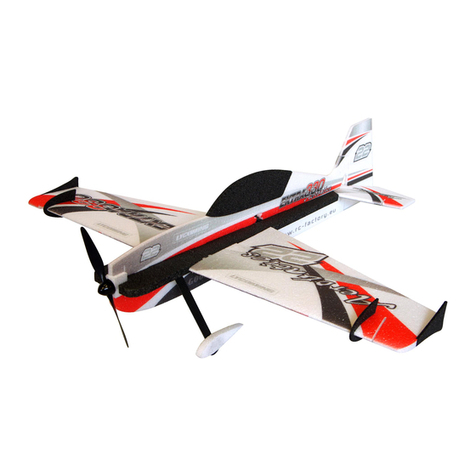
Enjoy your new EPP RS 352 1.2m
Your RC Factory team.
Specifications:
Wingspan: 1200 mm
Length: 1252 mm
AUW: 600 – 800g
Motor: 200 – 300W outrunner (ca 70 – 120g)
Servos: 12 – 20g good quality servos
Battery: 1600 – 2500 mAh 3s lithium polymer
