manuals.online logo
Brands
  1. Home
  2. •
  3. Brands
  4. •
  5. RC Factory
  6. •
  7. Toy
  8. •
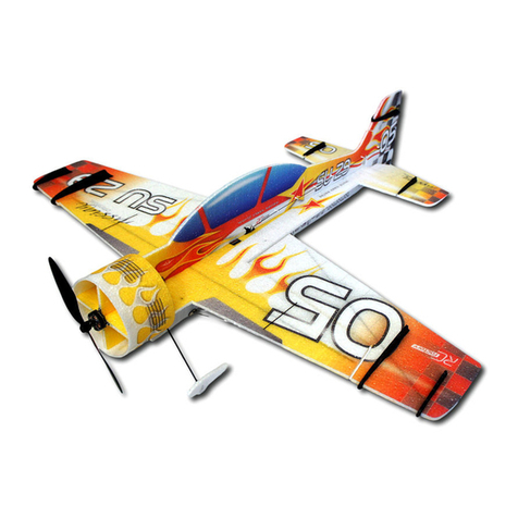
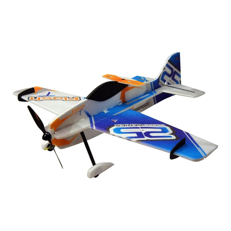
  9. RC Factory SU 29 Instruction Manual

RC Factory SU 29 Instruction Manual

Kit contents:
*fuselage
*canopy
*cowl
*stabilizer
*rudder
*wings
*landing gear
*carbon parts
*wheel covers
*building instructions
*accessory bag
1x frame, control arms and horns
2x wheel pants holder
1x landing gear base mount
2x landing gear lock
2x firewall holding tab
4x ball link clevis
2x wheel 50 mm
1x wheel 25 mm
1x tube 3/2 x 15 mm - elevator pushrod support
2x carbon 1x5x150 - elevator reinforcement
2x carbon 2x50 - aileron pushrod
1x kevlar string 1.5m - rudder pull pull system
Connection stainless hardware:
4x screw M1.6x4 ... ball clevises
2x screw M2x5 ... rudder hinges
2x screw M2x5 ... pull pull fasteners
1x screw M2x8 ... tailwheel axle
2x nut M2 ... tailwheel axle
2x Allen M3x14 ... landing gear axle
4x washer 3 ... landing gear (see Diag.)
2x nut M3 ... landing gear (see Diag.)
2x tapping screw 2.9x9 ... LG legs lock
2x Allen M2.5x6 ... motor attachment
2x Allen M3x6 ... alternative dtto
2x Z bend ... elevator pushrod
1.
1.
2.
3.
4.
5.
6.
7.
8.
4.
CFparts-frame, control arms and horns:
1. rudder hinge, fuselage part (2 pcs)
2. rudder hinge, lower rudder part
3. elevator servo arm extension
4. aileron control horns
5. rudder control horn
6. rudder servo arm extension
7. tailwheel leg
8. elevator control horn
You will also need:
Allen key No. 2
Philips screwdriver
standard screwdriver
CA glue + activator
hobby knife
flat file
sand paper 100 - 500
3 mm drill bit
a bit of patience for cca 5 hrs
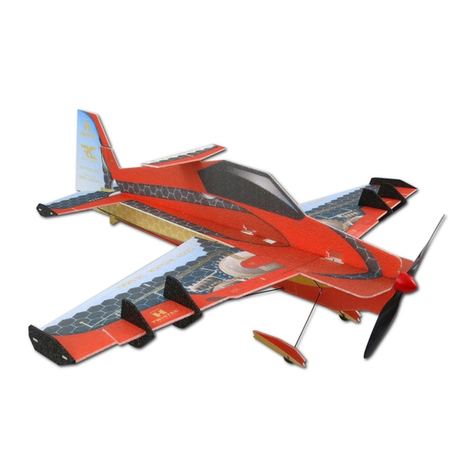
SU 29 – 1.2m aerobatic EPP model
Building instructions
Please follow the Diagram Sheet.
Tip: sand the GF (glass-fibre) parts before gluing
Diag. A, B
Push 2 flat cf strips (1x3x1000 mm) into the slots on the sides of the central
fuselage part (the „backbone“). Lay the backbone on its side on your building board
and make sure that it is perfectly straight. Apply CA glue over the cf strips and let
cure.
Diag. C
Glue the wing halves to the backbone. Note the small tabs that help you align the
wing correctly. Slightly push on the thickest part of the wing root to help the wing
settle in the correct incidence.
Important: if you glue the wing in normal (not inverted) position – the upper surface
facing up – the stabilizer cutout in the backbone should be also facing up. On Diag.
C the wing and the backbone are depicted in inverted position.
Diag. D
Locate two cf strips, 1x5x850 mm. Cut shallow slits into the wing and backbone,
spanwise, both on the upper and lower surface of the wing. Push the cf strips into
the slits and make sure that the wing and backbone assembly rests flat and straight
on a level building board. Apply thin or medium CA over the strips and let cure. Cut
shallow slits according to the mark 2 of the Diag. You will later mount the LG
(landing gear) locks here.
Diag. E
Likewise cut 2 slits into the stabilizer and push 2 cf strips (1x5x150mm) there. Lay
the stabilizer on a flat board and apply CA glue over the carbon strips.
Diag. F
Use medium CA to attach the (black EPP) canopy to the fuselage. Use your hobby
blade to separate the upper and lower part of the fuselage.
Diag. G
Rest your (wings and backbone) assembly on your board, inverted (bottom side up).
Assemble the LG mount and glue it to the backbone into the slits you made
according to Diag. D mark 2.
Diag. H
CA glue the lower fuselage part to the (now inverted) backbone. Attach (CA again)
the stabilizer to the backbone, first making sure that your alignment is perfect and
square.
Diag. I
Drill holes into the LG legs.
Diag. J
Push the LG legs into the LG mount. It may be a very tight fit, in such case use small
file to increase the openings. Use 2 tapping screws (2.9x9 mm) to attach the legs to
the mount. To release the legs, just loosen the screws a bit. Assemble the landing
gear according to the Diag. Gluing the EPP wheel covers to their holding tabs is the
last operation.
Diag. K
Now is the right moment to install the aileron servos. Make sure you find the right
position (consider cables lenghts, or use extension cables). We prefer the location at
about 1/3 of the wingspan. Cut out enough material from the wing to make the servo a
tight fit. Use hot glue (preferred) or thick (!) CA to glue the servos in place. You may
want to cover the servos in masking tape first for protection. Cut and glue the control
horns into the ailerons (follow the Diag.). Make sure you have the right geometry in
your servo horn – in servo neutral, the horn should be inclined cca 13° - not critical -
„backwards“, towards the aileron. Assemble the control links.
Diag. L
Use thin or medium CA to attach the upper fuselage part.
Diag. M
Assemble the tailwheel system and glue it to the lower rudder hinge. Get the other
part of the hinge and thread the M2x5 screw throught the corresponding holes to
make the hinge complete. There is no thread cut in the holes, but using some force
you may twist the screws through – they will push their way into the material since the
holes are just the right size. Create the upper hinge in the same way, the rudder
control horn is part of the upper hinge. Make corresponding cuts into the fuselage and
rudder, install the hinges using thin CA. Note – the cut for the lower hinge (and
tailwheel mount) in the rudder is T shaped when you look from the front.
Diag. N
CA glue the two plywood tabs into the motor mount.
Diag. O
Install the motor mount assembly into the backbone and fuselage. The motor thrust
line is 0° up and 1.3° to the right (the backbone is produced in the correct shape to
make this so). Use thin CA.
Diag. P
Elevator control link: the servo is on the side of the backbone. Cut out the material for
a tight fit, make sure that the location is within the reach of the servo cable to the
receiver. Glue in servo using preferably hot glue, or a thick CA. Again you may cover
the servo in masking tape first. Locate carbon tube 2/1 x 500 mm – your elevator
pushrod. On the elevator side, glue the stainless Z wire into the tube, leaving cca 10 -
15 mm out of the tube. Put the Z bend through the elevator control horn, cut and CA
glue the control horn into the elevator. Test the elevator movement. Thread the orange
supporting tube (3/2 x 15 mm) onto the pushrod and glue it to the backbone about half
way between the servo and elevator.
Install the Z bend on the servo side, with servo arm in neutral. If the ele. throws are
not sufficient, use the included servo extension horn.
Diag Q
Rudder control link: install the servo just like you did the elevator one. Attach the
extension servo horn to the original one using kevlar line and CA. Thread the two
M2 x 5 screws into the extension horn. The pull – pull system uses the included
kevlar line. Glue the line to the M2 screws, you can use them to tighten the line
when necessary. On the rudder side, just tie the line into the control horn (and also
use a drop of CA to prevent the sharp hole edges from tearing through the line).
Setting up and Trimming
We hope that you know how to connect and set up your RC system. If not, refer to
the relevant instruction manual or better ask a more experienced model aviator.
For maximum flight envelope, use the biggest mechanically possible control throws.
The rudder throws may be slight less, say 50°. The aileron throws should be the
same up and down. For first flights, or if you do not feel like an expert 3D flyer, use
somewhat lower throws – some 60% of the maximal ones. Use exponentials of 30
to 60% or to your best liking.
For first flights, we recommend centre of gravity (CoG) at some 125 mm from the
leading edge (root of the wing). At the beginning, use adhesive velcro tape to attach
the battery. This will help you find the right CoG (we like it quite aft, so much that the
plane tends to fly „hands off“ both normal and inverted). When happy with the CoG,
you may (or may not) cut a slot for the battery in the (upper) fuselage. The vertical
CoG may influence rolling tendencies (there should be none) in knife edge (KE) –
you may want to put the battery under the backbone if the model rolls to inverted
from KE. Some people don’t go this far and simply just use mixes to fix KE issues.
Our method for getting the right elevator trim is a power off vertical dive – the plane
should fall straigh down, like a brick J.
Aileron trim should be perfect both normal and inverted – if not, you may have a
lateral balance issue. Try putting the battery to the other side of the fuselage, this
should do most of the time.
After all these steps, the model should fly straight and also hover without any bad
tendencies. Hover can be adjusted by slight thrust line adjustments (insert washers
between the motor and the motor mount), but most likely there will be no need for
going that far.
Clean rolls (with no „barrel“ tendencies) can be achieved by dialing in the correct
aileron differential. If your radio does not allow this, you may just set different up and
down aileron throws). Equal up and down throws should work just fine, though.
Enjoy your new EPP Sukhoi!
Your RC Factory team.
Specifications:
Wingspan: 1200 mm
Length: 1252 mm
AUW: 600 – 800g
Motor: 200 – 300W outrunner (ca 70 – 120g)
Servos: 12 – 20g good quality servos
Battery: 1600 – 2500 mAh 3s lithium polymer
CACA
CACA
AB
D
1.
2.
carbon 1x5x850 mm
CACA
3.
carbon3x1x1000 mm
CACA
CACA
1.
2.
3.
E
carbon 1x5x150 mm
F
G
CACA
CACA CACA CACA
H
3mm
I
CACA CACA
C
Diagram sheet 1/2:
J
K
L
M
P
Q
CACA CACA
O
allen M3x16mm
nut M3
washer 3
tapping screw 2.9x9
13°
CACA CACA
CACA
CACA
M2x8
M2x5
M2x5
CACA
CACA
CACA
N
M2x5
125mm
Diagram sheet 2/2:

Other manuals for SU 29

3

Other RC Factory Toy manuals

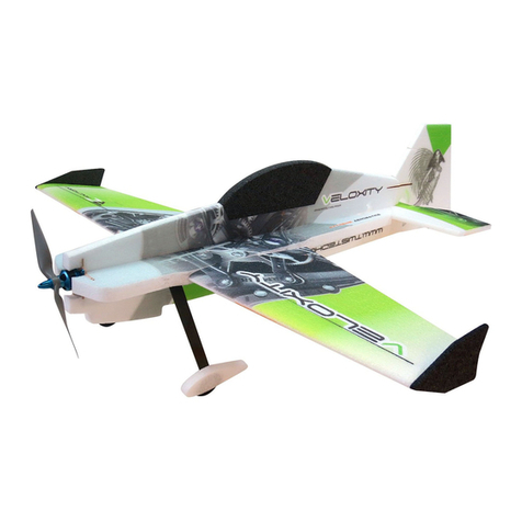
RC Factory VELOXITY User manual

RC Factory

RC Factory VELOXITY User manual

RC Factory Clik 21 User manual

RC Factory

RC Factory Clik 21 User manual

RC Factory Twisted Racer Series User manual

RC Factory

RC Factory Twisted Racer Series User manual

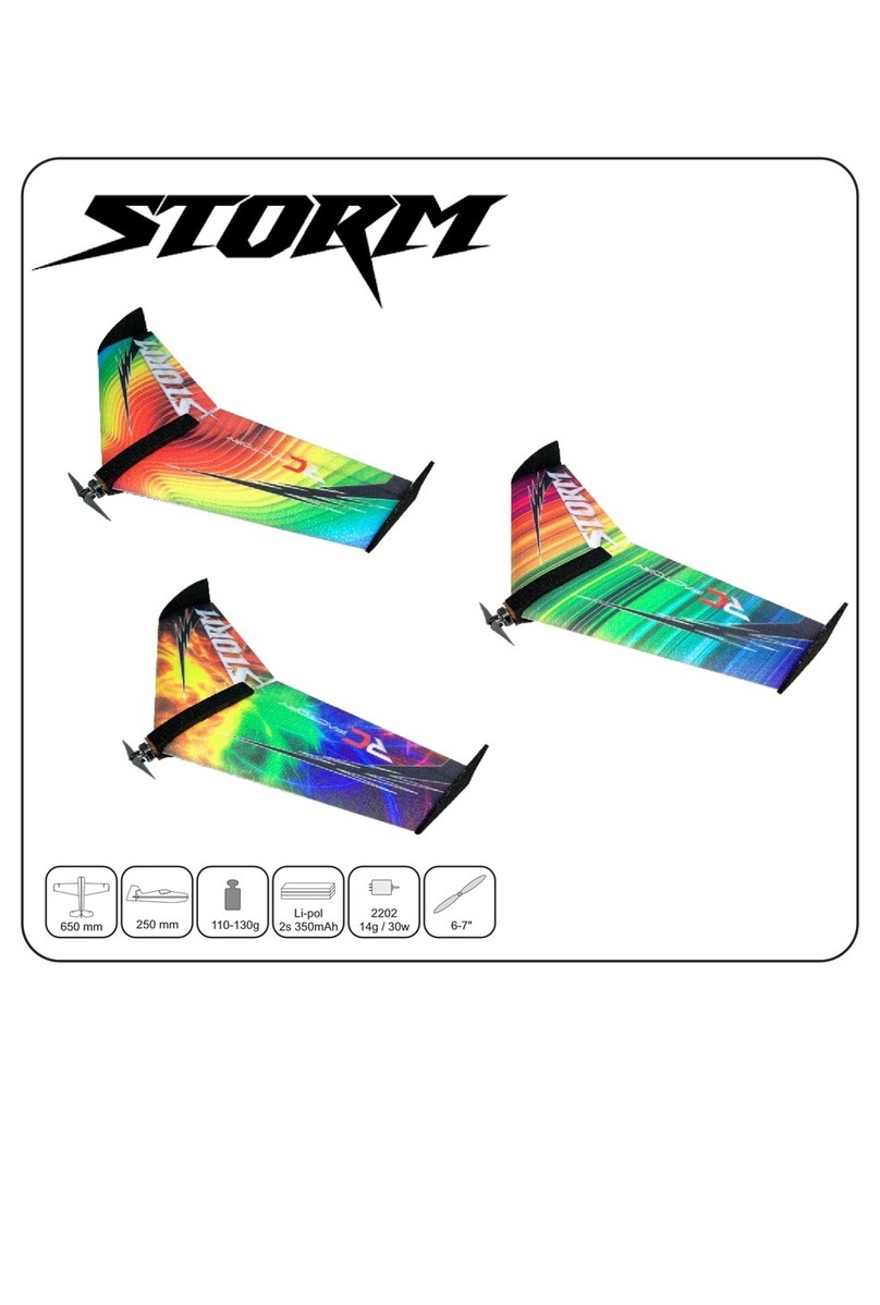
RC Factory Storm User manual

RC Factory

RC Factory Storm User manual

RC Factory SU 29 Instruction Manual

RC Factory

RC Factory SU 29 Instruction Manual

RC Factory Twisted Hobbys clik NG User manual

RC Factory

RC Factory Twisted Hobbys clik NG User manual

RC Factory Extra 330 User manual

RC Factory

RC Factory Extra 330 User manual

RC Factory Mini Crack Pitts Instruction Manual

RC Factory

RC Factory Mini Crack Pitts Instruction Manual

RC Factory Backyard Series User manual

RC Factory

RC Factory Backyard Series User manual

RC Factory VELOXITY User manual

RC Factory

RC Factory VELOXITY User manual

RC Factory SBACH 342 Instruction Manual

RC Factory

RC Factory SBACH 342 Instruction Manual

RC Factory FLASH 09M User manual

RC Factory

RC Factory FLASH 09M User manual

RC Factory Edge V3 Indoor User manual

RC Factory

RC Factory Edge V3 Indoor User manual

RC Factory F-22 Raptor User manual

RC Factory

RC Factory F-22 Raptor User manual

RC Factory Crack Pitts Backyard User manual

RC Factory

RC Factory Crack Pitts Backyard User manual

RC Factory Crack Pitts Instruction Manual

RC Factory

RC Factory Crack Pitts Instruction Manual

RC Factory SU 29 User manual

RC Factory

RC Factory SU 29 User manual

RC Factory Crack Turbo Beaver User manual

RC Factory

RC Factory Crack Turbo Beaver User manual

RC Factory Gee Bee User manual

RC Factory

RC Factory Gee Bee User manual

RC Factory SU 29 User manual

RC Factory

RC Factory SU 29 User manual

RC Factory Crack Yak User manual

RC Factory

RC Factory Crack Yak User manual

RC Factory Crack Laser Pro User manual
RC Factory

RC Factory Crack Laser Pro User manual

RC Factory Clik 4 NG User manual

RC Factory

RC Factory Clik 4 NG User manual

RC Factory Yak 55 Instruction Manual

RC Factory

RC Factory Yak 55 Instruction Manual
Popular Toy manuals by other brands

ATOMIC MASS GAMES STAR WARS LEGION CHEWBACCA manual

ATOMIC MASS GAMES

ATOMIC MASS GAMES STAR WARS LEGION CHEWBACCA manual

GRAUPNER Junior Line Series instruction manual

GRAUPNER

GRAUPNER Junior Line Series instruction manual

REVELL '65 Ford Mustang 2+2 Fastback Assembly guide

REVELL

REVELL '65 Ford Mustang 2+2 Fastback Assembly guide

Eduard Spitfire Mk.XVI manual

Eduard

Eduard Spitfire Mk.XVI manual

Fisher-Price DYM08 manual

Fisher-Price

Fisher-Price DYM08 manual

Eduard F-35A wheel bays & bomb bay 1/32 quick start guide

Eduard

Eduard F-35A wheel bays & bomb bay 1/32 quick start guide

Minicraft Models USAF C-130H Assembly instructions

Minicraft Models

Minicraft Models USAF C-130H Assembly instructions

LEGO SPEED CHAMPIONS Building instructions

LEGO

LEGO SPEED CHAMPIONS Building instructions

Faller Mountain Chalet 232507 Assembly instructions

Faller

Faller Mountain Chalet 232507 Assembly instructions

MGA Entertainment Rainbow HIGH 571049 quick start guide

MGA Entertainment

MGA Entertainment Rainbow HIGH 571049 quick start guide

Eduard 36 102 manual

Eduard

Eduard 36 102 manual

WLtoys v915 scale lama instruction manual

WLtoys

WLtoys v915 scale lama instruction manual

Smoby BN TWIN HIGHCHAIR manual

Smoby

Smoby BN TWIN HIGHCHAIR manual

REVELL KIT 1244 Assembly manual

REVELL

REVELL KIT 1244 Assembly manual

MODSTER HeliX 150 user manual

MODSTER

MODSTER HeliX 150 user manual

LEGO 75917 Jurrasic World Assembly guide

LEGO

LEGO 75917 Jurrasic World Assembly guide

Beyblade White Gabriel G instructions

Beyblade

Beyblade White Gabriel G instructions

Mattel FLUSHIN FRENZY game Setup

Mattel

Mattel FLUSHIN FRENZY game Setup

manuals.online logo
manuals.online logoBrands
  • About & Mission
  • Contact us
  • Privacy Policy
  • Terms and Conditions

Copyright 2025 Manuals.Online. All Rights Reserved.