manuals.online logo
Brands
  1. Home
  2. •
  3. Brands
  4. •
  5. RCA
  6. •
  7. Two-way Radio
  8. •
  9. RCA BRM350D Series User manual

RCA BRM350D Series User manual

Communications Systems
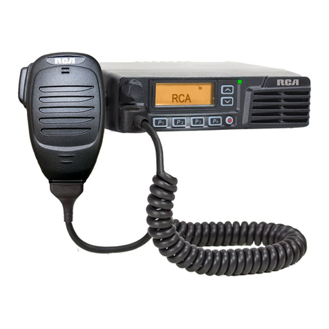
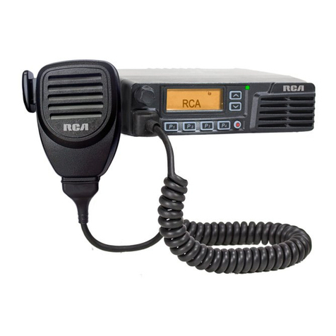
BRM350D Mobile
Two-Way Radio QUICK START GUIDE
BRM350D
Mobile Radio MM301HD
Mobile Mic
Microphone
Hanger
Mounting
Bracket
DC Power Cable
What’s Included:
Complete User Manual at: RCACommunicationsSystems.com
Notes:
Volume Control (Programmable)
LCD Display
Channel Selector (Programmable)
LED Indicator
Microphone Jack
Buttons P1 - P4 (Programmable)
On / O Button
Internal Speaker
1
2
3
4
5
6
7
8
TRANSCEIVER PREPARATION
Installation/Tools Needed
• Electric drill with 6mm bit or above
• Cross head screwdriver
• Hex socket sleeve (used for mounting 5mm × 16mm self-tapping screw)
When installing your transceiver, be sure to select a safe, convenient location. If you’re
installing inside your vehicle, choose a location that minimizes danger to your passengers
and yourself while the vehicle is in motion. Consider installing the unit so that knees or legs
will not strike the unit during vehicle operation. Try to pick a well ventilated location that is
shielded from direct sunlight for your installation location.
Install the mounting bracket in the vehicle using the supplied self-tapping screws (4), flat
washers (4), and spring washers (4). Position the bracket so that the 3 long screw hole
positions on the side of the mounting bracket are towards the rear of the bracket. (Figure 1)
Use the 3 screw positions on the side of the mounting bracket to determine the appropriate
angle of the transceiver. (Figure 2) Position the transceiver, then insert and tighten the
supplied hexagon SEMS screws (4) and flat washers (4). (Figure 3) Double check that all
hardware is securely fastened to ensure that vehicle vibration will not loosen the bracket
or transceiver.
Self-tapping screw
(5mm x 16mm)
Spring washer
Flat washer
Figure 1
Mounting Bracket
Figure 2
LCD Icon / STATUS INDICATION IN RADIO
Icon Name Icon Radio Status
Received Signal
Strength Indicator (RSSI)
The number of bars displayed represents the radio signal strength
and is only displayed while the radio is in receiving mode.
Message Icons
New message/unread message
Inbox is full
Sent successfully
Send failed
Send in-progress
Call Icons
Private Call
Group Call/All Call
Power Icons or Radio is set at low power (L) or high power (H)
Scan Icons
Scan feature is enabled
Priority scan detects activity on channel/group designated as
Priority 1 (if • is blinking) or Priority 2 (if • is steady)
Monitor Selected channel is being monitored
Tones Disable Tones are turned o
Emergency Icon Radio is in Emergency mode
Privacy Icon The Privacy feature is enabled
Talkaround Icon The radio is currently configured for direct radio to radio
communication. RCA and the RCA logo are trademarks of Technicolor SA and are used under license. All other trademarks are the property of their respective owners. © 2020 RCA Communications Systems. All rights reserved.
www.rcacommunicationssystems.com
[email protected]
(877) 822-2915
Created in U.S.A.
DC Power Cable Connection
Mobile Operation
Your vehicle battery must have a nominal rating of 12V. Never connect the transceiver to
a 24V battery. Be sure to use a 12V vehicle battery that has sucient current capacity. If
the current to the transceiver Is insucient, the display may darken during transmission, or
transmit output power may drop excessively.
1. Route the DC power cable supplied with the transceiver directly to the vehicle’s battery
terminals using the shortest path from the transceiver. If using a noise filter, it should
be installed with an insulator to prevent it from touching metal on the vehicle. We
recommend you do not use the power outlet/cigarette lighter socket as some power
outlets have an unacceptable voltage drop. The entire length of the cable must be
dressed so it is isolated from heat, moisture and the engine secondary (high voltage)
ignition system/cables.
2. After the cable Is In place, wrap heat-resistant tape around all fuse holders to protect it
from moisture and tie down the full run of cable.
3. To prevent the risk of short circuiting, disconnect other wiring from the negative (-)
battery terminal before connecting the transceiver.
SEMS Screws
Figure 3
(Radio back)
Figure 4
Fuse holders
4. Confirm the correct polarity of the connections, then attach the power cable to the
battery terminals; red connects to the positive (+) terminal and black connects to the
negative (-) terminal. Use the full length of the supplied cable without cutting o excess
even If the cable is longer than required. In particular, never remove the fuse holders
from the cable. (Figure 4)
5. Reconnect any wiring removed from the negative terminal.
6. Connect the DC power cable to the transceiver’s power supply connector. Press the
connectors firmly together until the locking tab connectors firmly together until the
locking tab clicks. (Figure 5)
Figure 5
Figure 6
Supplied cable
Fuse holder
Microphone Jack
For voice communications, connect a 600 Ω microphone equipped with an 8-pin modular
plug into the modular socket on the front of the main unit. Press firmly on the plug until the
locking tab clicks. (Figure 8)
Figure 8
Microphone Hanger
Attach the supplied microphone hanger using included screws in an easy to access
location that will not interfere with vehicle operation. (Figure 9)
Figure 9
Microphone hanger screws - 3mm x 10mm
Operational Status Indicators
Your radio indicates its operational status through the following:
• Display Icons
• Call Icons
• Sent Item Icons
• LED Indicator
• Audio Tones
Display Icons
The LCD display shows radio status, text entries, and menu entries. The following icons
will appear on the radio’s display. (see chart)
Audio Tones
Alert tones provide you with audible indications of the radio’s status or the radio’s
response to data received.
Continuous Tone - A monotone sound.
Sounds continuously until termination.
Periodic Tone - Sounds periodically depending on the duration set by the radio.
Repetitive Tone - A single tone that repeats itself until it is terminated by the user.
Momentary Tone - Sounds only once for a short period of time defined by the radio.
Antenna Connection
Before operating the radio, install an ecient, well-tuned antenna. The success of your radio
installation will depend largely on the type and installation of your antenna. The transceiver
will provide excellent results if the antenna system and radio installation are handled
properly. (Figure 6)
Use a 50 Ω impedance antenna and low-loss coaxial feed line that has a characteristic
impedance of 50 Ω to match the transceiver input impedance. Coupling the antenna to the
transceiver via feed lines having an impedance other than 50 Ω reduces the eciency of
the antenna system and can cause interference to nearby broadcast television and radio
receivers, and other electronic equipment.
Accessory Connections
External Speaker
If you plan to use an external speaker, choose a speaker with an impedance of 8 Ω. The
external speaker jack accepts a 1/8” (3.5 mm) mono (2-conductor) plug. (Figure 7)
Caution:
• Transmitting without first connecting an antenna or other matched load may
damage the transceiver. Always connect the antenna to the transceiver before
transmitting.
• All fixed stations should be equipped with a lightning arrester to reduce the risk of
fire, electric shock, and transceiver damage.
Making and Receiving Calls
1. Hold the microphone about 2” from your mouth when speaking and press the [PTT]
(push to talk) button. (Figure 10) The red LED lights during call.
2. Release [PTT] to return to the receive/listen (RX) mode. To receive your radio must be
switched to the proper channel and set with matching signaling or Color Code and
Group ID if used in digital mode.
Figure 10
PTT Button
(Push to talk)
Note on PTT: If the Talk Permit Tone is enabled, wait
until the short alert tone ends before talking.
During a call, if the Channel Free Indication feature
is enabled on your radio (programmed by your RCA
Communications Systems Dealer), you will hear a short
alert tone the moment the target radio (the radio that is
receiving your call) releases the PTT button, indicating the
channel is free for you to respond. You will also hear the
Channel Free Indication tone if your call is interrupted, for
example, when the radio receives an Emergency Call.
Complete User Manual at: RCACommunicationsSystems.com
Antenna connector
To antenna
Feed line connector
External Speaker
External Speaker
Connection
Figure 7
Other manuals for BRM350D Series

1

Other RCA Two-way Radio manuals

RCA BR200V User manual

RCA

RCA BR200V User manual

RCA RD3500 User manual

RCA

RCA RD3500 User manual

RCA MR240 User manual

RCA

RCA MR240 User manual

RCA RDR2600V User manual

RCA

RCA RDR2600V User manual

RCA Prodigi RDR1520 Series User manual

RCA

RCA Prodigi RDR1520 Series User manual

RCA PRODIGI RDR2750 User manual

RCA

RCA PRODIGI RDR2750 User manual

RCA RDR4330 User manual

RCA

RCA RDR4330 User manual

RCA RDR2500VX User manual

RCA

RCA RDR2500VX User manual

RCA RDR2500U User manual

RCA

RCA RDR2500U User manual

RCA MR240 User manual

RCA

RCA MR240 User manual

RCA APR100 User manual

RCA

RCA APR100 User manual

RCA RDR3600U User manual

RCA

RCA RDR3600U User manual

RCA BRM350D Series User manual

RCA

RCA BRM350D Series User manual

RCA BR200DV User manual

RCA

RCA BR200DV User manual

RCA RDR2000 Series User manual

RCA

RCA RDR2000 Series User manual

RCA PRODIGI RDR42 Series User manual

RCA

RCA PRODIGI RDR42 Series User manual

RCA digital Xsound BR250 VHF User manual

RCA

RCA digital Xsound BR250 VHF User manual

RCA BR850U User manual

RCA

RCA BR850U User manual

RCA RDR3600V User manual

RCA

RCA RDR3600V User manual

RCA RDR2500V User manual

RCA

RCA RDR2500V User manual

RCA RDR23 0 Series User manual

RCA

RCA RDR23 0 Series User manual

RCA BRM300DV User manual

RCA

RCA BRM300DV User manual

RCA RDR3500V User manual

RCA

RCA RDR3500V User manual

RCA RDR5200 User manual

RCA

RCA RDR5200 User manual

Popular Two-way Radio manuals by other brands

Midland X-Tra Talk LXT600 Series user manual

Midland

Midland X-Tra Talk LXT600 Series user manual

Motorola ST7000 Basic service manual

Motorola

Motorola ST7000 Basic service manual

Uniden MH120 owner's manual

Uniden

Uniden MH120 owner's manual

SAMCOM FPCN10A Operation manual

SAMCOM

SAMCOM FPCN10A Operation manual

Uniden Atlantis 290 owner's manual

Uniden

Uniden Atlantis 290 owner's manual

Sony U-Ceiver ICB-U655 operating instructions

Sony

Sony U-Ceiver ICB-U655 operating instructions

Motorola MTP8550E Series user guide

Motorola

Motorola MTP8550E Series user guide

Uniden frs 300 reference guide

Uniden

Uniden frs 300 reference guide

Uniden DSC BK owner's manual

Uniden

Uniden DSC BK owner's manual

Cobra microTalk PR 170 user guide

Cobra

Cobra microTalk PR 170 user guide

Cobra microTALK PR135 owner's manual

Cobra

Cobra microTALK PR135 owner's manual

Marvel Aavengers AV-212 quick start guide

Marvel

Marvel Aavengers AV-212 quick start guide

Motorola FV500 Series user guide

Motorola

Motorola FV500 Series user guide

Motorola Talkabout T5800 user guide

Motorola

Motorola Talkabout T5800 user guide

Mintech Y15 manual

Mintech

Mintech Y15 manual

Cobra microTalk LI 7000 WX owner's manual

Cobra

Cobra microTalk LI 7000 WX owner's manual

BK Radio KNG M-150 user manual

BK Radio

BK Radio KNG M-150 user manual

Motorola MC micro MPT 1327 Quick reference guide
Motorola

Motorola MC micro MPT 1327 Quick reference guide

manuals.online logo
manuals.online logoBrands
  • About & Mission
  • Contact us
  • Privacy Policy
  • Terms and Conditions

Copyright 2025 Manuals.Online. All Rights Reserved.