GRI PAA User manual

Proudly
Made in U.S.A.
1-800-445-5218
1-800-523-1227
(308) 235-4645
FAX (308) 235-3561
E-MAIL: [email protected]
GEORGE RISK INDUSTRIES, INC.
G.R.I. PLAZA
KIMBALL, NE 69145
WWW.GRISK.COM
WWW.GRISK.COM
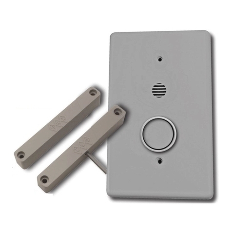
The new GRI Pool Access Alarm was designed as an aid in the prevention
of unattended access to a pool/spa area by a small child. Monitoring all
doors or windows with closed loop or open loop magnetic reed switches,
the Pool Access Alarm will sound an alarm should anyone too small to
manage the adult pass through feature attempt access to the pool/spa
area. For maximum protection all movable openings should be protected
in such a manner by the GRI Pool Access Alarm.
The PAA can be operated with an on-board 9 volt lithium battery or
with a 12 volt externally supplied DC power source, in which case the
battery will perform a back-up function should the externally supplied
source fail for any reason. Both power sources have been designed to
maintain a minimum sound pressure level of 85db at 10’. Should the
battery voltage drop below 8.3 Volts, a low battery mode will be initiated
and the unit will beep approximately every 50 seconds. Battery must be
replaced at this time.
It is suggested that some type of surge protection, such as the GRI CS-1
Current Sensor, be used between the power supply and the PAA.
Note: Unit will function at a minimum 5VDC at a very limited sounder volume.
This power level is considered total battery failure.
WARNING: THIS IS NOT A LIFE SAVING DEVICE.
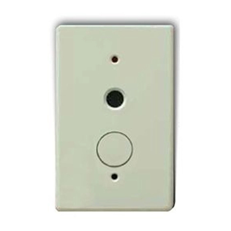
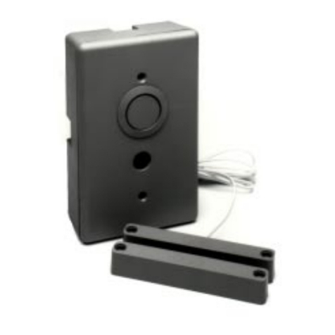
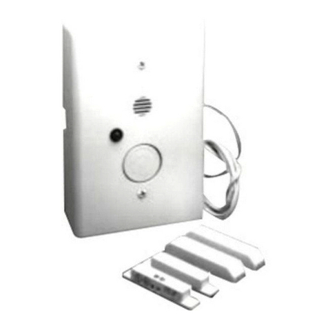
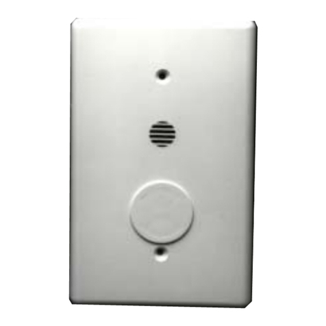
PAA Recessed Pool Access Alarm
PAA-S Surface Mount Pool Access Alarm
Part Numbers
ETL Listed
Pool Access Alarm
PAA
ETL tested to be in compliance with standard safety,
UL 2017, and Florida Building Commission Code
requirements, per ETL listing number 3035022
Exceeds operational requirements of model barrier codes
Microprocessor controlled
Monitors entry to pool and spa areas
Options set by jumpers include closed or open loop, instant
on or 7 second delay alarm, and 15 or 7 second adult shunt
Child resistant button guard built in
Surface or ush mount models
Capable of 2 year life with lithium battery
May be hard wired to remote 12 Volt 500 mA power
source, applied voltage must not exceed 15 VDC
PAA
PAA-S
WARRANTY: One year limited warranty against workmanship, material and factory defects.
1

Proudly
Made in U.S.A.
1-800-445-5218
1-800-523-1227
(308) 235-4645
FAX (308) 235-3561
E-MAIL: [email protected]
GEORGE RISK INDUSTRIES, INC.
G.R.I. PLAZA
KIMBALL, NE 69145
WWW.GRISK.COM
WWW.GRISK.COM
2
Pool Access Alarm PAA & PAA-S
(Next Gen 2022) Built to Scale
GEORGE RISK INDUSTRIES, INC.
KIMBALL, NE 69145
www.grisk.com
1-800-445-5218
E-MAIL: sales@grisk.com
1.70 in
(42.9 mm)
3.39 in
(85.8 mm) 1.31 in
(33.2 mm) 1.56 in
(38.27 mm)
5.19 in
(131.76 mm)
5.47 in
(137.31 mm)
5.41 in
(137.31 mm)
3.27 in
(83.72 mm)
.22 in
(5.5 mm)
.13 in
(3.3
mm)
ETL Listed
Pool Access Alarm
INSTALLATION:
The GRI Pool Access Alarm
mounts easily to the wall by
any door which allows access
to the pool/spa area. Using a
magnetic reed switch, the unit
will detect and announce an
open access by sounding a loud
continuous alarm. Two timed
options are oered: a maximum
seven (7) second delay mode
prior to sounding upon door
opening, or an instant alarm
sounding upon activation. A
surface mount and a recessed
mount model are offered in
both time options for a total of
4 dierent versions. All versions
incorporate a built-in pass through feature and deactivation button to allow adult access without alarm
sounding. Although the Pool Access Alarm cannot be turned o, this feature will simply deactivate the
alarm function for a maximum of fteen (15) seconds. During this time span the adult must exit and close
the door before the alarm sounds. Once the alarm is sounding, it can not be silenced by simply closing
the door. The deactivation button must also be depressed. The sounder cannot be disabled by holding
down the deactivation button.
If a screen is present on the opening giving access to the pool, a second magnetic reed switch should be
mounted on it and both switches wired in parallel or series depending upon the magnetic reed switches.
This conguration will allow the door to be open for ventilation since the unit will activate only when both
the screen and the door or window are opened.
If multiple openings lead to the area, the GRI Pool Access Alarm can monitor all by installing closed
loop switches which are wired in series or open loop switches in parallel. In this way, any opening will be
detected by the GRI Pool Access Alarm. A single deactivation button can also be wired at each opening to
utilize the pass through feature. Additional remote sounders may be wired in to extend sounder coverage.
Please contact your local GRI Distributer for information on remote options. Part numbers and wiring
diagrams are available from the factory.
CHILD
RESISTANT
BUTTON
GUARD
PAA-S
(surface mount)
PAA
(recessed)
WARRANTY: One year limited warranty against workmanship, material and factory defects.

POOL ACCESS ALARM
Operating Instructions
(Operating instructions must be le with the PAA)
Models PAA and PAA-S
Type SM Signaling Device
ETL Tested to be in compliance with Standard for Safety, UL 2017
and Florida Building Commission Code Requirements per ETL
listing number 3035022
NOTE: e POOL ACCESS ALARM must be installed and serviced
by a licensed installer or contractor.
APPLICATION
e POOL ACCESS ALARM is designed as an aid to detect unsupervised access to a pool and / or spa area by a small child.
Monitoring all doors and windows with magnetic reed switches the PAA will sound an alarm should anyone too small to mange
the adult pass through feature attempt to access the pool / spa area. When the alarm is sounding, it can only be turned o by
pressing the shunt / cancel button. If the door is still open for a predetermined time aer the button is pressed, the alarm will
sound again and continue until the door is closed and the button pressed. For maximum protection, all movable openings should
be protected in such a manner.
HOW TO USE
ere are several modes that the POOL ACCESS ALARM can work which is determined by local ordinances and implemented
by the installer.
One mode is that there can be a delay of 7 seconds between opening the door and the sounding of the alarm. is allows you to
open the door from the outside, enter the dwelling and shutting the door behind you, and then pushing the shunt button so that
the alarm will not sound. If the door is not shut or the button is not pressed the alarm will sound until the button is pressed and
the door shut.
e other mode is that a choice of how long the alarm will be silenced between pressing the button and the time it takes to shut
the door. e choice is 7 seconds delay or 15 seconds delay.
RECOMMENDED SYSTEM TESTING
Periodic system testing needs to be performed on a weekly basis and should incorporate the opening of each door and window
covered by the system and conrming the sounding of the alarm. It is recommended to replace the battery every year.
LOW BATTERY AND RED LED
To maintain maximum sounder volume, a low battery mode will be initiated if the voltage of the battery falls below 8.3 volts.
When this occurs the POOL ACCESS ALARM will beep once approximately every 50 seconds for two weeks prior to total bat-
tery failure. e battery must be replaced at this time.
e red LED indicates if there is a battery in the POOL ACCESS ALARM or not. If the PAA is powered solely by an external
power supply the LED will remain lit at all times. If the PAA is powered solely by a battery or if it is powered by an external pow-
er supply with a battery backup, the LED will ash approximately every 8 seconds. If there is a battery connected and the LED
remains solid, this is an indication that the battery is damaged. Failure to replace a damaged battery may make the PAA operate
dierently than intended. If the LED is not lit nor ashing, the PAA is not being powered and is not protecting the door. GRI
highly recommends using a backup battery.
3

LED Pattern Audible Pattern Meaning
Solid None Powered solely by external power supply. If
battery is connected, then the battery is damaged
and must be replaced.
1 Blink every 7~8 Seconds None Powered either via battery only or by external
power supply with battery backup.
None None PAA is inoperative, replace battery and / or
power supply.
Blink Beep every 50 seconds Low battery.
Blink or Solid Constant In alarm.
Rapid blinking One beep preceding the blinking PAA has options loaded, press the shunt button
once to activate.
Rapid blinking stops Two beeps Options have been activated successfully.
SPECIFICATIONS
Battery Ultralife 9 Volt Lithium U9VLJPFP
Battery Life Approximately 2 years
Low Battery Mode 8.3 Volts
External Power Supply 12 Volts DC 500 mA
Must be compliant to one of the following standards:
UL 294, UL 603, UL 864, or UL 1481
Maximum Current Draw 40 mA during alarm
Auxiliary Power Output 250 mA with External Power Supply
Battery Power: Only one GRI external sounder may be
attached (PAA-RS, PAA-RSB, PAA-SS or PAA-SSB) otherwise
the auxiliary power output must not be used.
Mounting Height Reference local code
Sounder Rating 85 dB at 10Ft
Switch Closed Loop with jumper 4 installed
Open Loop with jumper 4 removed
DISCLAIMER
THE GRI POOL ACCESS ALARM IS NOT A LIFE SAVING DEVICE. It is intended to serve strictly
as a monitoring device on doors and windows to help prevent unattended access to pool and spa areas.
If there are questions on the operation or maintenance of the POOL ACCESS ALARM, please contact the factory at:
George Risk Industries
802 South Elm Street
Kimball, NE. 69145
(308) 235-4645
If you believe your POOL ACCESS ALARM is not operating correctly please contact your installation company (names and
phone numbers of installation companies can be obtained by contacting George Risk Industries).
PAA DOC VERSION: 10-FEB-2020
4

POOL ACCESS ALARM
Installation Instructions
DESCRIPTION
e POOL ACCESS ALARM uses a microprocessor to monitor the magnetic reed switches, shunt / cancel button, battery volt-
age, and to provide the timing options. e recessed version (PAA) is designed to t inside a plastic single gang utility box, while
the surface mount version (PAA-S) may easily be mounted to the wall of any structure.
MODEL VERSIONS:
PAA POOL ACCESS ALARM for use with a recessed nonmetallic outlet box
PAA-S POOL ACCESS ALARM, surface mount with included box
NOTE: Nonmetallic outlet box must be compliant to one of the following standards: UL 514C, NFPA 70, or NEMA OS-2.
OPTIONS
ere are four sets of options which are congurable by jumpers between the board and the faceplate of the POOL ACCESS ALARM.
ese options are the delay time of the alarm, the shunt time, whether the AUX out follows the alarm or the door, and open loop or
closed loop. e diagram on the back page shows the location of these jumpers and the setting for the desired options.
WIRING SPECIFICATION
For connection of optional remote equipment and door contact switches, a Belden CAT5 CL2 or equivalent cable is recommend-
ed. For the connection of the 12 volt power supply to the alarm unit a Belden 18-2 CL2-CMR 300V 60º C or equivalent wire
is recommended. In all cases installer should reference current local NEC code and / or code requirements set forth by local
housing authority or code enforcement jurisdiction.
INSTALLING THE DOOR SENSOR
Install the magnetic reed switch on the door according to the manufacturer’s installation instructions. If there is a screen door,
a switch should be installed on it as well. e switches should be connected in parallel as in Figure 1. In this conguration the
POOL ACCESS ALARM will only activate if both doors are open. Next, run the wires from the switch(es) to where the PAA will
be located on the wall.
INPUTS
e POOL ACCESS ALARM provides a single input which is used to trigger it from an armed state by a simple momentary
opening or closing of the circuit between Terminals 2 and 5. If using a CLOSED LOOP (normally open magnetic reed switches)
then the jumper on Pin 4 must be installed. If using an OPEN LOOP (normally closed magnetic reed switches) then the jumper
on Pin 4 must be removed.
Multiple triggers can be utilized by wiring in a series conguration to the input provided. For example, multiple doors can be pro-
tected with one PAA by installing closed loop contacts on each door and wiring in a series circuit to each other, back to the PAA.
An additional input is also provided to remote the shunting or pass through feature of the alarm. A normally open, button type,
momentary push to close switch can be wired to Terminals 2 and 4. Actuation or momentary closure will initiate the pass
thorough shunt feature. Multiple locations can be so equipped by wiring button type switches in parallel to each other or home-
running all remote buttons to Terminals 2 and 4.
Pool Access Alarm PAA & PAA-S
(Next Gen 2022) Built to Scale
GEORGE RISK INDUSTRIES, INC.
KIMBALL, NE 69145
www.grisk.com
1-800-445-5218
E-MAIL: sales@grisk.com
1.70 in
(42.9 mm)
3.39 in
(85.8 mm) 1.31 in
(33.2 mm) 1.56 in
(38.27 mm)
5.19 in
(131.76 mm)
5.47 in
(137.31 mm)
5.41 in
(137.31 mm)
3.27 in
(83.72 mm)
.22 in
(5.5 mm)
.13 in
(3.3
mm)
INSTALLATION
WIRING DIAGRAM
Single Door with screen
Figure 1. Wiring Diagram
SCREEN DOOR
Sounder
Power LED
Shunt/Cancel
5

OUTPUTS
An auxiliary output consisting of a transistor pulling to ground can be used to control on / o functions of additional equipment.
Example uses include cameras or wireless transmitters. ese outputs can also be utilized as an alarm trigger to the security panel.
e AUX output can be set to actuate only when the POOL ACCESS ALARM sounder is sounding or it can be programmed to fol-
low the door. In this conguration, the shunt pass-through feature of the PAA will not negate the activation of the transistor output.
Power for auxiliary output is supplied by Terminal 6 and ground is actuated by Terminal 7. Terminal 6 voltage will be the same
as the main power supply, i.e. 12 volts if by external power and 9 volts if by battery power.
NOTE: Maximum current is 250 mA.
All wires going from the AUX Output must stay within the room containing the PAA.
INSTALLING THE POOL ACCESS ALARM
NOTE: e POOL ACCESS ALARM must be mounted as per local code or regulation.
Remove the POOL ACCESS ALARM from the surface mount case if using the PAA-S. Knockouts are provided on this case for
wire access. Attach the surface mount case directly to the wall or existing xture, or it may be mounted to cover a plastic single
gang electrical box. Choose the options wanted and set the jumpers according to Figure 2 on the back page. Attach the wires
from the door switch to Terminals 2 and 5. It does not matter which wire goes in which location. If using an external 12 volt
DC supply, run the wires from the power source to the alarm unit and attach the positive voltage to Terminal 1 and ground to
Terminal 2. If battery power or battery backup is desired, connect an Ultralife lithium battery at this time. As soon as power is
supplied by the battery or an external power supply, the PAA will have the options loaded and is operating.
e LED will stay lit if it is on external power supply only. If there is a battery inside for either backup or powered only by a bat-
tery the LED will ash every 8 seconds.
WARNING: If using a battery only and the LED stays lit, this is an indication that the battery is defective. Do not use the battery.
e POOL ACCESS ALARM will not function as specied in these instructions.
If using the surface mount PAA., secure battery in Velcro holder which is attached to the case. If using the recessed PAA, remove
plastic covering of the Velcro battery holder exposing the adhesive. Attach battery holder to a location which is away from all live
parts of the PAA in a plastic (NOT METAL) outlet box and reassemble the PAA with the button on the bottom and the sounder
on top. Use the screws provided to secure the faceplate to the PAA.
WARRANTY
One year against workmanship, material, and factory defects. Proof of Purchase is required with returns.
* PAA DOC VERSION: 10-FEB-2020
Pool Access Alarm PAA & PAA-S
(Next Gen 2022) Built to Scale
GEORGE RISK INDUSTRIES, INC.
KIMBALL, NE 69145
www.grisk.com
1-800-445-5218
E-MAIL: sales@grisk.com
1.70 in
(42.9 mm)
3.39 in
(85.8 mm) 1.31 in
(33.2 mm) 1.56 in
(38.27 mm)
5.19 in
(131.76 mm)
5.47 in
(137.31 mm)
5.41 in
(137.31 mm)
3.27 in
(83.72 mm)
.22 in
(5.5 mm)
.13 in
(3.3
mm)
INSTALLATION
WIRING DIAGRAM
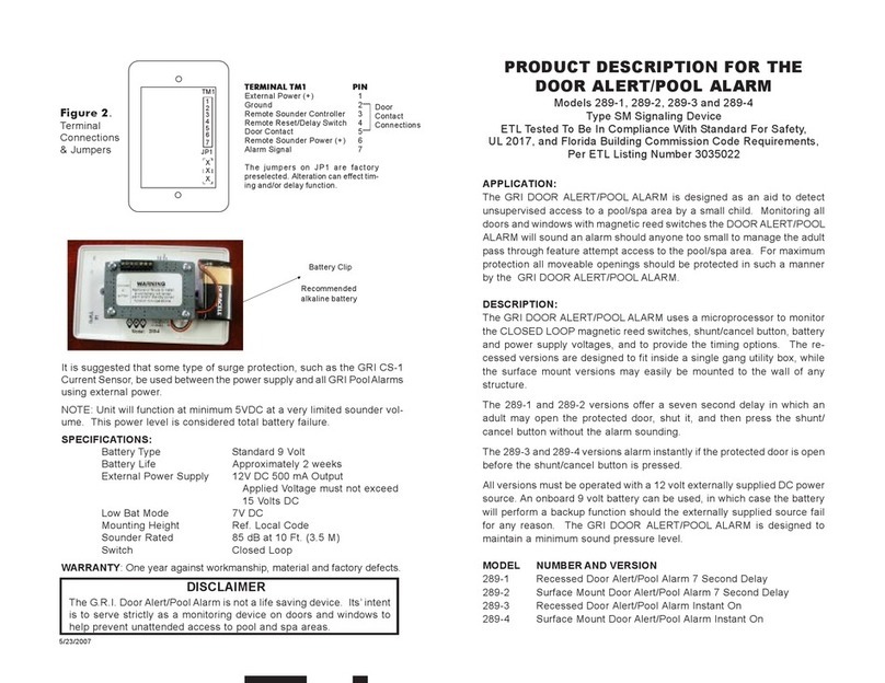
Figure 2.
Terminal Connections
and Jumpers
TERMINAL BLOCK
1 External Power (+)
2 Ground
3 Remote Sounder Controller
4 Remote Reset/Delay Switch
5 Door Contact
6 AUX Power
7 AUX Output
JUMPER / NO JUMPER
1 Instant on / 7 Second Delay
2 15 Second Shunt / 7 Second Shunt
3 Relay Follow ALARM / DOOR
4 Closed Loop / Open Loop
6
This manual suits for next models
1
Table of contents
Other GRI Security System manuals