3
ENGLISH
anchors, screws, brackets not supplied by RCF etc.), which must guarantee the
security of the system / installation over time, also considering, for example,
the mechanical vibrations normally generated by transducers.
9. RCF S.p.A. strongly recommends this product is only installed
by professional qualified installers (or specialised firms) who
can ensure a correct installation and certify it according to the
regulations in force.
The entire audio system must comply with the current standards
and regulations regarding electrical systems.
10. There are numerous mechanical and electrical factors to be considered
when installing a professional audio system (in addition to those which
are strictly acoustic, such as sound pressure, angles of coverage, frequency
response, etc.).
11. HEARING LOSS
Exposure to high sound levels can cause permanent hearing loss. The acoustic
pressure level that leads to hearing loss is different from person to person
and depends on the duration of exposure. To prevent potentially dangerous
exposure to high levels of acoustic pressure, anyone who is exposed to these
levels should use adequate protection devices. When a transducer capable of
producing high sound levels is being used, it is therefore necessary to wear ear
plugs or protective earphones.
See the technical specifications in the instruction manual for the maximum
sound pressure the loudspeaker is capable of producing.
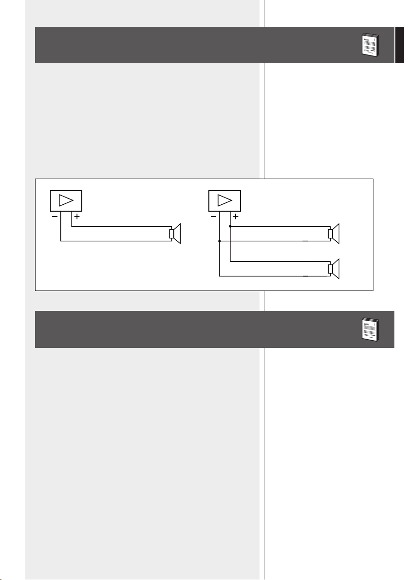
12. To ensure a correct musical reproduction, loudspeaker phase is to be
respected (loudspeakers are connected respecting the amplifier polarity).
This is important when loudspeakers are installed adjacent one another, for
instance, in the same room.
13. To prevent inductive effects from causing hum, noise and a bad system
working, loudspeaker lines should not be laid together with other electric
cables (mains), microphone or line level signal cables connected to amplifier
inputs.
14. The loudspeaker cable shall have wires with a suitable section (twisted,
if possible, to reduce inductive effects due to surrounding electro-magnetic
fields) and a sufficient electrical insulation.
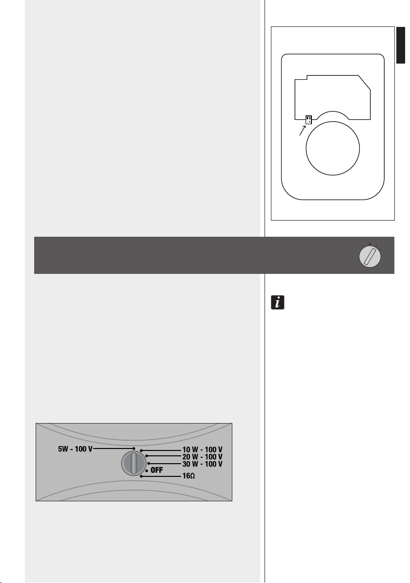
OPERATING PRECAUTIONS
-Install this loudspeaker far from any heat source.
-Do not overload this product for extended periods of time.
-Never force the control elements (keys, knobs, etc. ).
-Do not use solvents, alcohol, benzene or other volatile substances for
cleaning the external parts of this product.
-If the speaker is used in particulary cold places, drive it with a low signal for
5-10 minutes before using it at maximum power.
OPERATING PRECAUTIONS