RDP E725 User manual

RDP Customer Document
Technical Manual for the
E725 Serial Communication
Doc. Ref CD1423H
Issue H
This manual applies to units of mod status 7 ONWARDS
BS EN ISO 9001
Certificate No. FM13141
Affirmed by Declaration
of Conformity
USA & Canada All other countries
RDP Electrosense Inc. RDP Electronics Ltd
2216 Pottstown Pike
Pottstown, PA 19465
U.S.A.
Grove Street, Heath Town,
Wolverhampton, WV10 0PY
United Kingdom
Tel (610) 469-0850
Fax (610) 469-0852
Tel: +44 (0)1902 457512
Fax: +44 (0)1902 452000
www.rdpelectrosense.com
www.rdpelectronics.com

2
INDEX
1INTRODUCTION.....................................................................................................3
2IDENTIFYING YOUR HARDWARE ........................................................................4
2.1 Decoding the E725 Part Number ............................................................................4
2.2 Decoding the Start-up Display Sequence ...............................................................4
3CONNECTION DETAILS ........................................................................................5
3.1 RS232 Connection Details ......................................................................................5
3.2 RS485 Connection Details ......................................................................................5
4ESTABLISHING SERIAL COMMUNICATIONS ......................................................7
4.1 IMPORTANT WARNING BEFORE SENDING COMMANDS..................................7
4.2 Serial Communications Protocol. ............................................................................7
4.3 Establishing RS232 Communications. ....................................................................7
4.4 Establishing RS485 communications. .....................................................................7
5SERIAL COMMUNICATION COMMANDS .............................................................9
5.1 Passwords / User level............................................................................................9
5.2 Quick Reference of runtime commands ..................................................................9
5.3 Example of a runtime command..............................................................................9
5.4 Details of runtime commands................................................................................10
5.5 Quick Reference of setup commands ...................................................................12
5.6 Example of a setup command...............................................................................13
5.7 Serial Communication Commands........................................................................13
6USING THE E725 WITH WINDOWS TERMINAL .................................................17
6.1 Windows Terminal Settings...................................................................................17
7FAULTFINDING. ...................................................................................................19
7.1 Communications problems....................................................................................19
7.2 Commands not being actioned..............................................................................19

3
1 INTRODUCTION
The E725 is fitted with a serial port. This will be either RS232 or RS485 depending upon
the options ordered. If it is RS232, one unit may be connected to each RS232 port on the
host computer. For RS485, up to 256 unit may be connected via an RS232/485 converter
to a single RS232 port on the host computer.
The communication interface between the E725 and the host computer has been designed
to be very flexible and it is very simple to program the E725 using a terminal emulation
program (e.g. Microsoft Windows 3.1™ Terminal Program). Alternatively a high-level
programming language with ASCII based string functions (such as Visual Basic, Delphi,
Pascal etc) could be used to develop data acquisition and control software.
RDP can supply RS232 or RS285 leads and converters. Please contact our sales
department for additional information and pricing.

4
2 IDENTIFYING YOUR HARDWARE
Before you proceed, take a few minutes to familiarize yourself with the hardware that you
have. Note the part number from the label on the outside of the instrument. Note
particularly the 'Serial Output' and the 'Input Board', both of which affect serial
communications. The table below is a summary of the part number structure; full details
are in the main manual for the E725 instrument.
2.1 Decoding the E725 Part Number
230/115/105 = Indicates the choice of AC supply voltage selected (+5/-15%)
SUPPLY 5/12/24 = Indicates the choice of DC supply voltage selected (+50/-25%)
AC = For LVDT/half-bridge etc.
INPUT BOARD DC1/DC2/DC3 = for strain gauge/amplified transducers
0= none
R/RS = Relay/limit card
FR/FRS = Fast relay/limit card
FM = fast MAX/MIN board
OPTION BOARD
2AC/2DC1/2DC2/
2DC3
= Second input card
0= RS232
SERIAL OUTPUT 1= RS485
SPECIAL OPTION 0= None
Example:-
E725 - 230 - AC - FR - 0 - 0….
…has 230V ac supply, and AC input board, a fast limit card,
RS232 output and no special options
2.2 Decoding the Start-up Display Sequence
Connect the E725 to the correct supply and switch on. Note that the E725 identifies itself
on start-up. Of particular importance are b, c and d. Note these values.
Step Example Description
1 E725 Instrument Identification
2 1.03 Software Version Number
3 AC-0 The input and option board fitted in the form AA-B
AA= Signal input board B= Option board
AC = AC signal input version 0 = No board fitted.
DC = DC signal input version 1 = Relay/Limit Board.
2 = Fast Relay/Limit Board.
3 = MAX / MIN / TIR Board.
4 = Second input card
4 00.0.4 Summary of the current COMMS settings in the format 'XX.Y.Z'
XX= Module Address (2 digits, Hexadecimal)
Y = Communication Mode: 0 = RS232, 1 = RS485
Z = Baud Rate: 0 = 600, 1 = 1200, 2 = 2400, 3 = 4800,
4 = 9600, 5 = 19200, 6 = 38400, 7 = 57600

5
3 CONNECTION DETAILS
If you do not wish to make up your own lead, please contact RDP sales and we shall be
happy to quote.
The connections depend upon whether the E725 is fitted with the optional RS485 protocol,
or the standard RS232. Use sections 2.1 & 2.2 to establish if the unit is RS232 or RS485.
If the standard RS232 is fitted, only one unit may be connected to each RS232 port on the
computer, as detailed in 3.1
If the optional RS485 is fitted, multiple units may be connected via an RS485/RS232
converter as detailed in 3.2.
3.1 RS232 Connection Details
A Single E725 can be connected to a computer using the RS232 communication link (see
figure 1). Alternatively if your computer is fitted with more than one serial communication
port then it would be possible to connect more than one E725 to the computer by
connecting the first E725 to serial communications port 1 (COM1), a second E725 to serial
communications port 2 (COM2) etc.
Figure 1 E725 to PC RS232 Communication Lead.
3.2 RS485 Connection Details
The factory fitted RS485 option allows a maximum of two hundred and fifty six E725s to be
connected to a single RS232 serial communication port using a single twisted-pair cable.
The other advantages of RS485 communication over the standard RS232 are higher baud
rate, longer cable lengths (up to 1200 metres) and higher noise immunity.
It is generally recommended that a good quality twisted pair (e.g. Belden 9841) be used
with characteristic impedance of 120R. If Belden 9841 cable cannot be used then any
screened twisted-pair cable with characteristic impedance of 100 to 120R can be used but
the maximum distance or communication baud rate may be reduced.

6
It is also recommended the instruments connected to the RS485 network be connected in
series to minimise loading, data reflections and maintain data integrity.
In RS485 applications, the two transmission lines must be properly terminated, and a
single resistor across the receiver input pair on the Model 485F25 normally provides
adequate termination at the computer end. It is important that the last E725 in the network
is terminated by connecting a resistor across the two transmission lines (see figure 2).
In some instances, particularly in RS485 multi-drop operation, noise may be detected at
the receiver. In the multi-drop configuration, there can be brief periods when no
transmitter is enabled, which allows the network to float. So it is recommended that two
extra resistors be added externally to the Model MA485F, so that the network is biased to
about 1 to 2 volts when all transmitters are disabled (see figure 2). For factory supplied
leads, this will have been done.
The RS485 standard specifies that a maximum of 32 devices can be connected to a single
driver. Therefore, if more than 32 E725's are to be connected to a network then it will be
necessary to install RS485 repeaters at strategic points around the network. It may also
be advantageous to use repeaters if the network is spread over a wide area.
Figure 2 RS485 Wiring Diagram

7
4 ESTABLISHING SERIAL COMMUNICATIONS
4.1 IMPORTANT WARNING BEFORE SENDING COMMANDS
Some serial commands can affect the analogue output and limit relays. If the E725 is
being used in a control application, carefully consider the implications of sending RS232
commands.
4.2 Serial Communications Protocol.
Refer also to sections 2 & 3.
Baud rate The E725 baud rate is selectable. See section 2.2 for details of
how to find the current setting. The default value is 9600
Parity = NONE
Start bits = 1
Stop bits = 1
Number of data bits = 8
4.3 Establishing RS232 Communications.
Please follow these steps in order to verify serial communication.
a) Turn off both the E725 and the host device (PC, PLC etc)
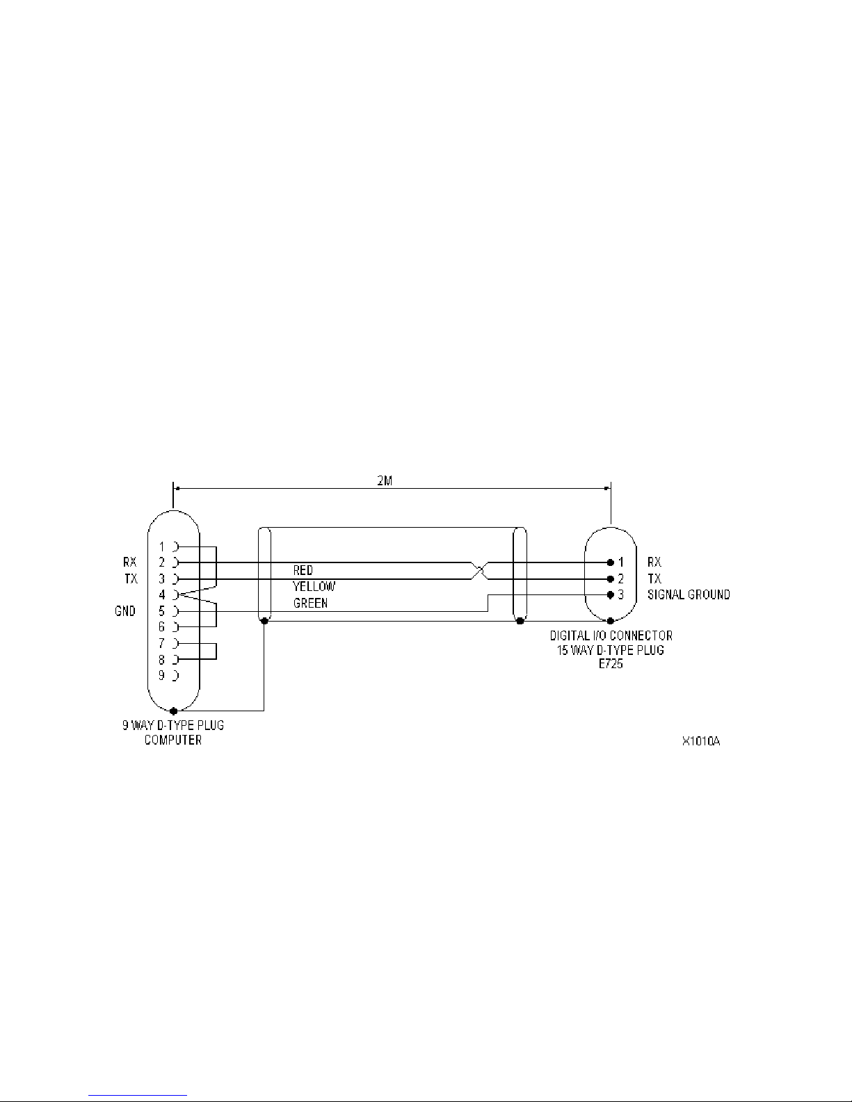
b) Connect the two devices using a lead wired as detailed in section 3.1.
c) Turn on both the E725 and the host computer.
d) Start a serial communications program on the host computer. It is strongly
recommended that a terminal emulation program is used, rather than any high level
software. We recommend Microsoft Terminal for windows 3.1, or a similar program.
e) Configure the terminal software with the correct serial communications protocol and
baud rate, as detailed in section 4.2.
f) Type '#00 sys'* and press the enter key. The E725 should respond with a short line
of identification text, including the unit part number and software version. If this
happens, communication has been successfully established.
* This assumes that the module address is the default value of '00'
See section 7 for faultfinding information.
4.4 Establishing RS485 communications.
Note. The E725 units must have the optional factory fitted RS485 option. See sect 2.
a) Turn off both the E725 and the host device (PC, PLC etc)
b) Connect ONE of the E725 units to the communications lead, leaving all other sockets
unconnected. Ensure that the RS232/485 converter is connected and turned on.
c) Turn on both the E725 and the host computer.
d) Start a serial communications program on the host computer. Initially a terminal
emulation program should be used, rather than any high level software. We
recommend Microsoft Terminal for windows 3.1, or a similar program.
e) Configure the terminal software with the correct serial communications protocol, as
detailed in section 4.2. The baud rate of the communications program should be set
to that of the E725. See section 2.2 to find out the E725 baud rate setting.
f) Send the following commands.

8
Command (replace nn ,X &
Y!), then press <ENTER>
Help notes Unit
response*
#00 set user level,1,X X= level 1 password, default = 1
(see E725 manual for further info)
Assumes that module address is 00.
Nothing or
"OK"
#00 set comms,nn,485,YY,on Set nn to the desired module address. This
should be unique and not '00'. Suggested
value is 01 for the first unit, then 02 etc.
Set YY to the baud rate that the E725 is
currently set to. I.e. do not change it!
'OK'
#nn save nn should match the address as set above 'OK'
#nn sys nn should match the address as set above 'E725..."
etc
* If the stated unit response is not received, there is a problem. Repeat the command
sequence from the start. If this does not solve the problem, see section 7.
Fix a label to the E725 indicating its address. This will assist in system commissioning.
Once the first unit is working, test it in all sockets to ensure that all sockets are working.
Use the #nn sys command to verify communication in each socket
g) Disconnect the first unit and repeat steps b to f for all of the units giving each a
unique non-zero address. It is not necessary to re-test all sockets.
h) Connect all units to the network and test communications with each address.
If desired, the baud rate of each unit may now be changed, however, they must all be set
to the same value. To change the baud rate, first establish communications with the units
and then send the following to each of the units
Command
Press <ENTER> after command
Help notes Unit
response
#nn set user level,1,X Where X is the level 1 password 'OK'
#nn set comms,XX,485,YY,on Where XX is the new module address
and YY is the new baud rate,
(e.g. 9600)
'OK'
#XX save XX = new module address 'OK'
Baud rate changes do not take effect until the E725 has been reset. When all units have
been re-programmed, turn them all off, then on. The new baud rate will now be set.
Remember to change the baud rate of the host device before re-establishing
communications.

9
5 SERIAL COMMUNICATION COMMANDS
Read section 4.1 for important information.
Commands to the E725 may be sent via a simple terminal emulation program or any
programming language with ASCII based string functions (such as Visual Basic, Delphi,
Pascal etc).
A unit will only respond if it receives '#' followed by 2 digits, corresponding to its address.
The E725 can only respond to serial communication during normal operation. In set-up
mode communication is disabled.
5.1 Passwords / User level
In order to protect calibration parameters, several of communications commands require a
password to be set before they will be accepted. The E725 has 3 levels of security; user
level 1, 2 & 3. Some commands do not require a password. The password level for all
commands is detailed by the command description. Once a password has been entered, it
will remain valid until either it is cleared or returning the unit to run mode terminates set-up.
5.2 Quick Reference of runtime commands
The following table lists all the runtime commands that do not require a password.
Command Description
SYS Prints software version number.
GET ERROR Prints error status
CLR ERROR Clears error status.
RESET Resets the E725.
RESET PEAKS Clears the stored MAX, MIN and TIR values.
RESET LIMITS Resets any latched limits.
CLR USER LEVEL Clears the current user level (i.e. password).
ZERO Calculates the tare reading (i.e. zeros the display)
CLR ZERO Clears the tare reading.
DISPLAY INPUT Displays the normal input signal
DISPLAY MAX Displays the MAX input signal.
DISPLAY MIN Display the MIN input signal.
DISPLAY TIR Display the TIR input signal.
DISPLAY F1 Selects display function 1
DISPLAY F2 Selects display function 2
DISPLAY F3 Selects display function 3
DISPLAY F4 Selects display function 4
PRINT DATA Prints the current display value.
GET DATA Prints the current display value.
SCAN Prints the current display value.
PRINT CAL Prints the shunt cal. value (DC board) or the excitation voltage (AC board)
5.3 Example of a runtime command
For example, suppose we want to zero the display using serial communication on the
E725 with address 00, then the following command must be sent:
#00 ZERO

10
5.4 Details of runtime commands
#nn SYS Password not required
Sending this command causes the E725 to return the current software version
#nn GET ERROR Password not required
Returns the number of lines of command received since the FIRST error occurred. CLR
ERROR resets the counter. If no errors have occurred, the response string will state this.
#nn CLR ERROR Password not required
Causes the error counter to be reset.
#nn RESET Password not required
This causes the E725 to reset, which is equivalent to switching the E725 off and on. This
command will clear any change sent to E725 since the last SAVE command.
#nn RESET PEAKS Password not required
This causes the E725 to reset the MAX, MIN and TIR values.
#nn RESET LIMITS Password not required
This causes the E725 to reset any latched limits.
#nn CLR USER LEVEL Password not required
Clears the current user level (password).
#nn ZERO Password not required
Same as pressing Zero from the front panel. See E725 manual for further info.
#nn CLR ZERO Password not required
Same as pressing Clear Zero from the front panel. See E725 manual for further info.
#nn DISPLAY INPUT Password not required
This command forces the E725 to display the normal (dynamic) input signal.
#nn DISPLAY MAX Password not required
This command forces the E725 to display the MAX input signal.
#nn DISPLAY MIN Password not required
This command forces the E725 to display the MIN input signal.

11
#nn DISPLAY TIR Password not required
This command forces the E725 to display the TIR input signal.
#nn DISPLAY F1 Password not required
Only valid if dual channel option board is fitted or the customer has ordered the optional
software function keys and it forces the E725 to display function 1 (i.e. input signal).
If the dual channel board is fitted then the display, limits and analogue output will
track channel A.
#nn DISPLAY F2 Password not required
Only valid if dual channel option board is fitted or the customer has ordered the optional
software function keys and it forces the E725 to display function 2.
If the dual channel board is fitted then the display, limits and analogue output will
track channel B.
#nn DISPLAY F3 Password not required
Only valid if dual channel option board is fitted or the customer has ordered the optional
software function keys and it forces the E725 to display function 3.
If the dual channel board is fitted then the display, limits and analogue output will
track channel (A+B)/2.
#nn DISPLAY F4 Password not required
Only valid if dual channel option board is fitted or the customer has ordered the optional
software function keys and it forces the E725 to display function 4.
If the dual channel board is fitted then the display, limits and analogue output will
track channel (A-B).
#nn PRINT DATA
#nn GET DATA
#nn SCAN
Password not required
All 3 commands do the same thing, the duplication is to provide compatibility with other
RDP serial devices. They cause the current display value to be transmitted.
#nn PRINT CAL Password not required
This command will either print the excitation voltage (ac input board only) or the shunt cal
value (dc board only). The shunt cal value display will be the gross value (i.e. the local
zero offset will not be subtracted from the reading so that the shunt cal value is constant
regardless of the tare reading).
It is important to remember that the LIMITS, FAST MAX/MIN/TIR and analogue output will
all change to reflect either the shunt cal value or excitation voltage.

12
5.5 Quick Reference of setup commands
Command Description
CLR SETUP Clears the current set-up in volatile memory
SAVE Saves the current set-up to non-volatile memory.
SET USER LEVEL Facilitates entry of the user level and password.
SET PASSWORDS Facilitates changes to passwords for levels 1, 2 and 3.
SET COMMS Programs the communication protocol and baud rate.
SET DATA LOGGING Programs the data-logging mode of operation.
SET FRONT PANEL Enables/Disables the front panel.
SET EXCITATION Programs the excitation voltage for the DC input board.
SET GAIN Programs the gain for the input board.
SET DP Programs Full scale value with decimal places (I.e. cal point)
SET SCALING Calibrates the input signal.
SET LINEARISATION Programs straight-line linearisation.
SET POLYNOMIAL Programs polynomial linearisation.
SET ENGINEERING OFFSET Programs the engineering offset.
SET TARE POINT Programs the tare point.
SET FILTER VALUE Programs the filter value.
SET COUNTS Programs the count facility
SET LIMIT Programs the limits.
The table lists all the set-up commands that require a password. The relevant password is
listed on the far right hand side of the page next to the command. For example, SET
COMMS requires User Level 3.
The communication interface between the E725 and the host computer has been designed
to be very flexible by using simple English commands. This makes it very simple to
program the E725 using a terminal emulation program or alternatively any high-level
programming language with ASCII based string functions (such as Visual Basic, Delphi,
Pascal etc) can be used to develop data acquisition and control software.
Since the E725 can be used on a RS485 network, all units expect to be sent a two digit
hexadecimal address before any command, this address must be preceded by # and the
command line dos not match the programmed address of the E725 then the command will
be ignored.
The E725 can only respond to serial communication during normal operation (i.e.
pressing a front panel key, applying a digital input or if the instrument is in the set-up
menu disables serial communication).
For example, suppose we want to zero the display using serial communication on the
E725 with address 00, then the following command must be sent : -
#00 ZERO
In this section, all the E725 commands will have the following format : -
#nn COMMAND,P1,P2
where #nn Please substitute nn with the address of the E725 instrument which you wish
to communicate.

13
COMMAND The command to be sent.
,P1,P2 Optional command line parameters.
It is important to remember that all instructions sent to the 650 must be terminated
with a carriage-return line-feed sequence.
The E725 can also be configured for software handshaking, so that the E725 will respond
with either: -
OK If a valid command that does not request data (e.g. ZERO) has been
received.
ERROR If the E725 does not recognise the command or the necessary password
has not been set.
Data String If the host computer requests data (e.g. Print Data).
All responses from the E725 are terminated with a carriage-return, line feed (ASCII
characters 13, 10) sequence.
If the E725 does not receive a character after serial communication has been
requested (i.e. the ‘#’ character has been received) then the E725 will time out,
erasing all received data and resuming normal operation.
5.6 Example of a setup command
Command Comments
#00 SET USER LEVEL,1,1 Sets the user level to 1, using the default password
for level 1, which is 1! Note that '#00' indicates a
unit having address '00'
#00 SET COMMS,01,232,19200,on Sets the communications parameter to address 01,
RS232, 19200 baud and handshaking on.
#01 SAVE Saves the new settings. (Note change in address!)
#01 RESET Note that the new baud rate is not active until after
the unit has been reset. Change host settings!
5.7 Serial Communication Commands
#nn CLR SETUP User Level 1, 2 or 3
Clears all set-up parameters for the current user level, INCLUDING CALIBRATION.
#nn SAVE User Level 1, 2 or 3
This command saves all of the settings to non-volatile memory. Until this command is
used, all settings will be lost if the power is switched off or the unit is reset.

14
#nn SET USER LEVEL,L,P User level & password required
The E725 has 3 levels of security; user levels 1, 2 & 3. Each of the user levels has a
separate password. In order to change settings, first check the user level required, then
enter it here if you are authorised. Level 3 is the highest level (giving access to levels 1, 2
and 3). The default password for level 3 access is 3.
Ldefines the user level you wish to enter
Pdefines the password for the user level
For example, to enable access to the calibration and limits menu, send the command: -
Example: - #00 SET USER LEVEL,2,2
#nn SET PASSWORDS,P1,P2,P3 User Level 3
This commands re-programs the three passwords, which are used to access the various
E725 set-up facilities
Where P1 is the password used for the limits menu (User Level 1).
P2 is the password used for the calibration menu (User Level 2).
P3 is the password used for the Configuration Set-up Menu (User Level 3).
#nn SET COMMS,Address,Protocol,BaudRate,HandShaking User Level 1
This command sets up the communications parameters for the E725.
Address Sets the module address of the E725. This only needs to be changed if a
number of E725 instruments are connected to the same RS485 network.
Acceptable values are 00 to FF hexadecimal.
Protocol Sets the comms protocol for the E725. Acceptable values are 232 or 485.
BaudRate Sets the communications baud rate of the E725. Acceptable values are
600, 1200, 2400, 4800, 9600, 19200, 38400 or 57600.
HandShaking Sets the response made by the E725 to a command. If OFF then the E725
does not make any response to commands otherwise if ON the E725 will
respond with OK or ERROR if the command was erroneous.
Changes to the baud rate are not effective until the E725 has been reset.
For example, to set the E725 address to zero, RS232 communication at 9600 and
software hand-shaking the command would be: - #nn SET COMMS,00,232,9600,ON
#nn SET DATA LOGGING,Mode User Level 1
The data logging command controls the flow of display data to the serial port. When off,
data is only sent when requested by an appropriate command. In any of its 3 different
modes, data is sent as detailed below.

15
Mode = OFF Disables data logging function.
Note that data streaming continues between setting the user level and
sending the 'off' command.
Mode = HOLD The displayed value is sent each time the digital HOLD input is
pulsed. See the instrument manual for details of Digital Inputs. Display
flashes whilst HOLD is applied.
The maximum frequency at which the HOLD pin can be pulsed is
40Hz but the serial port should be monitored to ensure that the last
piece of serial data has been transmitted before the next HOLD pulse
is applied.
Mode = DISPLAY The displayed value is sent each time display updates (4/sec approx.)
Mode = CONT Data is sent as fast as possible. The transmission rate depends upon
limit settings, filter value and calibration method but particularly baud
rate. At 57600 baud, between 70 and 120 readings per sec (nom) is
possible, at 9600 baud this will reduce to 50 to 60 readings (nom).
NOTE: - The speed of limit and MAX/MIN response will be reduced.
Example:- #00 SET DATA LOGGING,DISPLAY causes the display data to be transmitted
each time the display updates.
#nn SET FRONT PANEL,Mode User Level 3
Mode = ON or OFF. Turns front panel keys on or off
#nn SET EXCITATION,Value User Level 3
This command is used to set the excitation voltage. Acceptable values are 1, 3, 5 or 10.
Disconnect the transducer before changing this as excessive voltage could destroy the
transducer. Measure the excitation with a voltmeter before connecting the transducer.
#nn SET GAIN,Value User Level 3
This command is used to set the gain of the input board. Acceptable values are 1, 2, 3, 4,
5, 6, 7, or 8. See the E725 manual for details.
#nn SET Counts, Count User Level 1
This command allows you to enter a number which will force the calibrated input signal to
be displayed in the specified resolution. For example, if the display resolution is 1 decimal
places and 25 is entered, then the calibrated input signal will be displayed in increments of
0.25 (e.g. 0.00, 0.25, 0.50 etc.).
Count Sets the required number of counts.
Notes – The count facility only applies to the displayed input signal and does not
apply to:
1. The cal. signal (i.e. AC excitation voltage, displayed shunt cal. value)
2. Signal used for the software limits or the MAX/MIN/TIR values.
3. Data printed to the RS232/485 port.

16
For example
#00 SET USER LEVEL,1,1
#00 SET COUNTS,25 (i.e. Count = 25)
#nn SET DP,Resolution,Full Scale,Count User Level 2
This command is used to set the number of decimal places, the transducer calibration
point (i.e. full scale value) and desired display resolution.
Resolution Sets the Number of decimal places for display. Acceptable values 0,1,2,3 or 4.
Full Scale Sets the transducer calibration point (i.e. full-scale value).
Count Sets the required number of counts.
For example
#00 SET USER LEVEL,2,2
#00 SET DP,2,100,25 (i.e. Decimal Places = 2
Full Scale Value = 100
Count = 25)
#nn SET SCALING,M,C User Level 2
This command is used to set the transducers calibration data, so that the transducer is
scaled according to the following formulae: - Y = Mx + C + E + T
Where Y = Scaled data in engineering units
M = Calibration scaling factor
C = Calibration zero offset
E = Engineering offset
T = Tare Reading
x = ADC Counts
#nn SET LINEARISATION,CP0,M0,C0,CP1,M1,C1.. ,CPn,Mn,CnUser Level 2
This command is used to set the transducers calibration data, so that the transducer is
linearised using the straight-line method.
CP0First calibration break point
M0
First scaling constant
C0
First offset constant
This option cannot not be used if either the fast limit or the fast MAX / MIN / TIR board is
fitted and the maximum number of break point is eleven.
#nn SET POLYNOMIAL,Cn, .. ,C1,C0User Level 2
This command is used to set the transducers calibration data, so that the transducer is
linearised using a polynomial.
Note This option cannot not be used if either the fast limit or the fast MAX / MIN / TIR board
is fitted and the maximum number of coefficients is 16 (i.e. n = 15).

17
#nn SET ENGINEERING OFFSET,Value User Level 2
Used to set the engineering offset and tare point to the entered value.
#nn SET TARE POINT,Value User Level 2
This command is used to set the tare point to the entered value.
#nn SET FILTER VALUE,Value User Level 1
This command is used to set the filter value. Acceptable values are 1 to 9.
#nn SET LIMIT, Limit, Operation, Mode, Set-Point, Deviation,
Hysteresis, Latched
User Level 1
This command is used to configure the limit. The command line parameters are:
Limit Defines the limit to be configured. Acceptable values are L1, L2, L3 and L4.
Operation
Defines the operation of the limit.
A
cceptable values are OFF, HI, LO and
DEVIATION.
Mode Defines the signal that the limit is to be compared against, Acceptable values
are GROSS, NETT, TARE, MAX, MIN and TIR.
Set Point
Defines the limits set point.
Deviation
Defines the limits deviation value.
Hysteresi
s
Defines the limits hysteresis value.
Latched Defines whether the limit is working is latched or unlatched mode. Acceptable
values are LATCHED or UNLATCHED.
6 USING THE E725 WITH WINDOWS TERMINAL
The E725 has been fully tested with Microsoft Windows® Terminal program on Windows
3.1 and 3.11 for Work Groups and Windows 95. It will probably work with other versions
also. Remember to configure the communication settings.
Assuming that you have connected the E725 to your computer using the appropriate lead
(turn both units OFF before connecting or disconnecting), you are now ready to
communicate with the E725.
To test communications, type:
#00 SYS and press the enter key. (Assuming the E725 address is 00)
The E725 should respond, probably with its type and version number.
This verifies that you have full communications with the E725. If not, check the settings,
communication for the correct serial communications settings.
6.1 Windows Terminal Settings.
Settings, Terminal Preferences: - (Local Echo = ON), (CR > CR/LF = outbound)
Settings, Communications: - 8 data, no Parity, 1 Stop, Flow = Xon/Xoff. Baud as required.

18
Remember to save the terminal settings otherwise they will be lost.

19
7 FAULTFINDING.
7.1 Communications problems.
1) Check that the terminal emulation program on the host PC is configured to send both
'Carriage Return' and 'Line Feed' when the enter key is pressed. The E725 will not
respond otherwise.
Carriage return = ASCII code 13, sometimes entered as /013 or ^m
Line feed = ASCII code 10, sometimes entered as /010 or ^j
2) Check that the setting for the COM port on the host computer is the actual port that
the E725 is connected to.
3) Check the communications settings.
4) The most common reason for communications failure is incorrect connections in the
serial lead. If after the above have been re-checked there is still no communication,
double check the serial lead connections, then check again for good measure!
Before you contact RDP, ensure that you have tested communications as detailed above.
We are unable to assist unless it can be shown that the communications problems are not
as a result of programming errors in applications software. Testing communications on a
terminal program is essential.
7.2 Commands not being actioned.
Remember that many commands require the correct user level (password) to be set and
many are volatile until the SAVE command is sent.
Other manuals for E725
1
Table of contents