Realtek RTL8201(L) User manual

RTL8201(L)
2002-01-18 Rev.1.04
1
REALTEK SINGLE CHIP
SINGLE PORT 10/100MBPS
FAST ETHERNET PHYCEIVER
RTL8201(L)
1. Features........................................................................ 2
2. General Description .................................................... 2
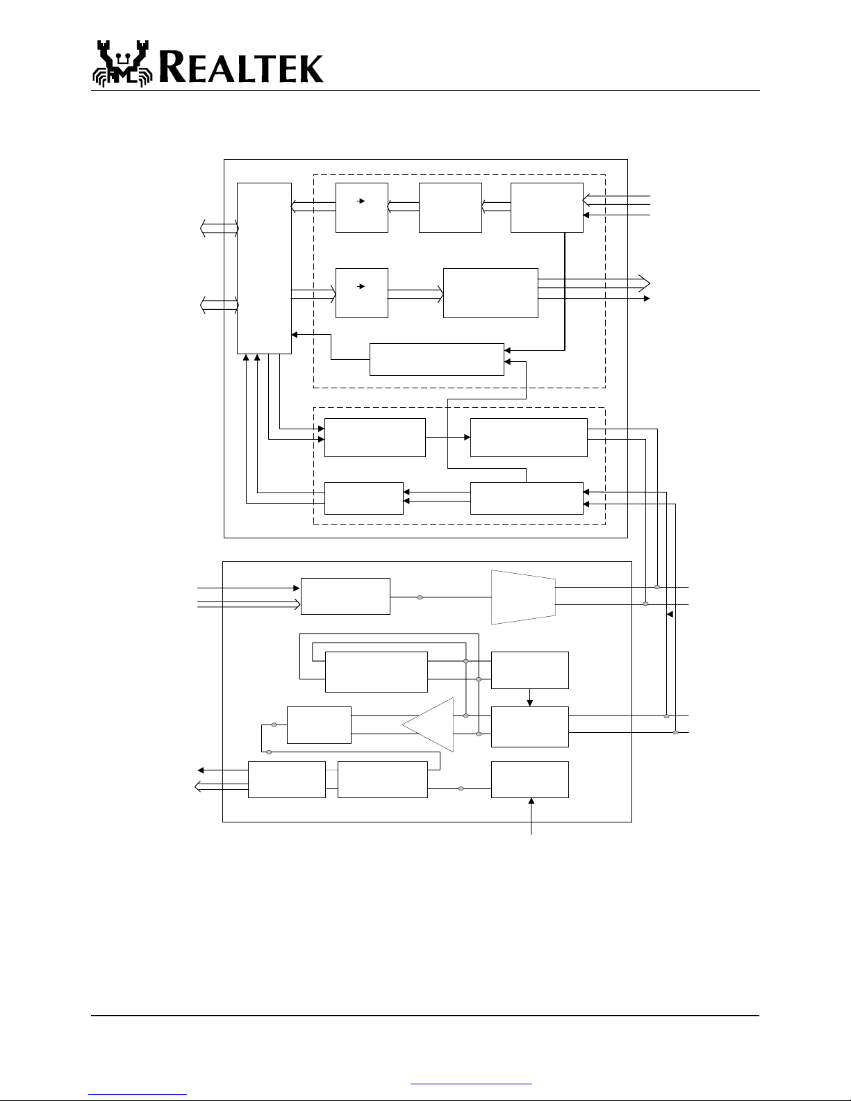
3. Block Diagram............................................................. 3
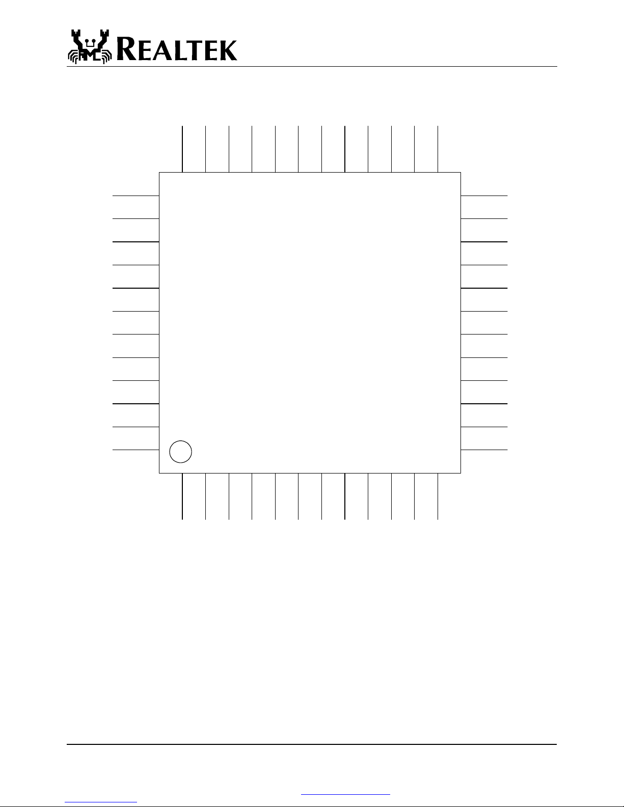
4. Pin Assignments .......................................................... 4
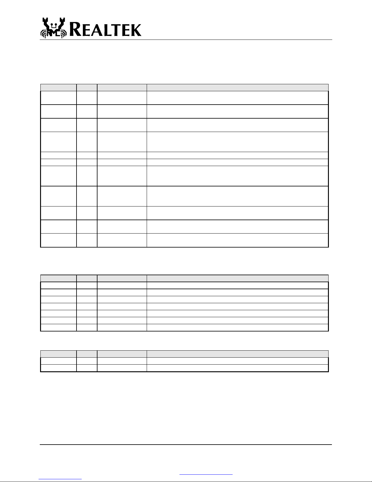
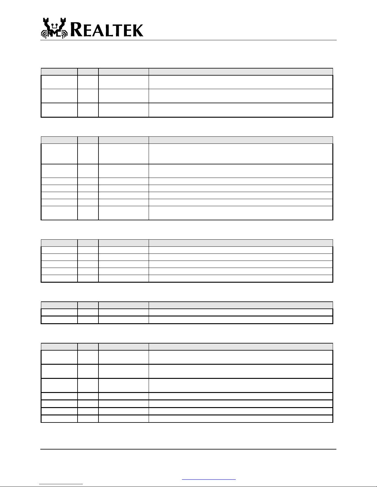
5. Pin Description ............................................................ 5
5.1 100 Mbps MII & PCS Interface ............................. 5
5.2 Serial Network Interface (SNI) .............................. 5
5.3 Clock Interface ....................................................... 5
5.4 100Mbps Network Interface................................... 6
5.5 Device Configuration Interface .............................. 6
5.6 LED Interface/PHY Address Config...................... 6
5.7 Reset and Test pins................................................. 6
5.8 Power and Ground pins.......................................... 6
6. Register Descriptions .................................................. 7
6.1 Register 0 Basic Mode Control .............................. 7
6.2 Register 1 Basic Mode Status................................. 9
6.3. Register 2 PHY Identifier 1................................. 10
6.4. Register 3 PHY Identifier 2................................. 10
6.5. Register 4 Auto-negotiation Advertisement................ 11
6.6 Register5Auto-NegotiationLinkPartnerAbility.................. 12
6.7 Register 6 Auto-negotiation Expansion (ANER) . 14
6.8 Register16NwaySetup(NSR)....................................... 14
6 . 9 Register 17 Loopback, Bypass, Receiver Error Mask (LBREMR).... 15
6.10 Register 18 RX_ER Counter (REC)................... 15
6.11 Register1910MbpsNetworkInterfaceConfiguration.......... 15
6.12 Register 20 PHY 1_1.......................................... 15
6.13 Register 21 PHY 1_2.......................................... 16
6.13 Register 22 PHY 2 ............................................. 16
6.14 Register 23 Twister_1 ........................................ 16
6.15 Register 24 Twister_2 ........................................ 16
7. Functional Description ............................................. 17
7.1 MII and Management Interface............................ 17
7.2 Auto-negotiation and Parallel Detection .............. 18
7.3 Flow control support ............................................ 18
7.4 Hardware Configuration and Auto-negotiation.............. 19
7.5 LED and PHY Address Configuration................. 20
7.6 Serial Network Interface ...................................... 20
7.7 Power Down, Link Down, Power Saving, and Isolation Modes 21
7.8 Media Interface .................................................... 21
7.8.1 100Base Tx/Rx ............................................. 21
7.8.2 10Base Tx/Rx ............................................... 22
7.9 Repeater Mode Operation .................................... 22
7.10 Reset, Power, and Transmit Bias........................ 22
8. Electrical Characteristics ......................................... 23
8.1 D.C. Characteristics ............................................. 23
8.1.1. Absolute Maximum Ratings........................ 23
8.1.2. Operating Conditions................................... 23
8.1.3. Power Dissipation........................................ 23
8.1.4 Supply Voltage: Vcc ..................................... 23
8.2 A.C. Characteristics ............................................. 24
8.2.1 Transmission Without Collision ................... 24
8.2.2 Reception Without Error............................... 24
9. Mechanical Dimensions ............................................ 25
Tel: +49(0)234-9351135 · Fax: +49(0)234-9351137 E-MAIL:[email protected] http://www.cornelius-consult.de

RTL8201(L)
2002-01-18 Rev.1.04
2
1. Features
The Realtek RTL8201(L) is a Fast Ethernet Phyceiver with MII interface to the MAC chip. It provides the following
features:
Supports MII interface
Supports 10/100Mbps operation
Supports half/full duplex operation
IEEE 802.3/802.3u compliant
Supports IEEE 802.3u clause 28 auto negotiation
Supports power down mode
Supports operation under Link Down Power
Saving mode
Supports repeater mode
Speed/duplex/auto negotiation adjustable
3.3V operation with 5V signal tolerance
Low operation power consumption
Adaptive Equalization
25MHz crystal/oscillator as clock source
Multiple network status LED support
Supports 7-wire SNI (Serial Network Interface)
interface
Flow control ability support to co-work with
MAC (by MDC/MDIO)
48-pin LQFP package
2. General Description
The RTL8201(L) is a single-port Phyceiver with an MII (Media Independent Interface). It implements all 10/100M Ethernet
Physical-layer functions including the Physical Coding Sublayer (PCS), Physical Medium Attachment (PMA), Twisted Pair
Physical Medium Dependent Sublayer (TP-PMD), 10Base-Tx Encoder/Decoder and Twisted Pair Media Access Unit
(TPMAU). It is fabricated with an advanced CMOS process to meet low voltage and low power requirements.
The RTL8201(L) can be used as a Network Interface Adapter, MAU, CNR, ACR, Ethernet Hub, Ethernet Switch.
Additionally, it can be used in any embedded system with an Ethernet MAC that needs a twisted pair physical connection.
Tel: +49(0)234-9351135 · Fax: +49(0)234-9351137 E-MAIL:[email protected] http://www.cornelius-consult.de

RTL8201(L)
2002-01-18 Rev.1.04
3
3. Block Diagram
RXIN+
RXIN-
TXO+
TXO -
RXC 25M
25M
TXC 25M
TXD
RXD
TD+
Variable Current
3 Level
Driver
Master
PPL
Adaptive
Equalizer
Peak
Detect
3 Level
Comparator
Control
Voltage
MLT-3
to NRZI
Serial to
Parrallel
ck
data
Slave
PLL
Parrallel
to Serial
Baseline
wander
Correction
5B 4B
Decoder
Data
Alignment Descrambler
4B 5B
Encoder Scrambler
10/100
half/full
Switch
Logic
10/100M Auto-negotiation
Control Logic
Manchester coded
waveform
10M Output waveform
shaping
Data Recovery Receive low pass filter
RXD
RXC 25M
TXD
TXC 25M
TXD10
TXC10
RXD10
RXC10
Link pulse
10M
100M
MII
Interface
SNI
Interface
Tel: +49(0)234-9351135 · Fax: +49(0)234-9351137 E-MAIL:[email protected] http://www.cornelius-consult.de

RTL8201(L)
2002-01-18 Rev.1.04
4
4. Pin Assignments
RTL8201
7. TXC
2. TXEN
3. TXD3
4. TXD2
5. TXD1
6. TXD0
16. RXC
1. COL
23. CRS
22. RXDV
18. RXD3
19. RXD2
20. RXD1
21. RXD0
24. RXER
25. MDC
26. MDIO
46. X1
47. X2
33. TPTX-
34. TPTX+
28. RTSET
31. TPRX+
30. TPRX-
43. ISOLATE
40. RPTR/
RTT2
39. Speed
38. Duplex
37. ANE
41. LDPS
44. MII/
SNIB
9. LED0/
PAD0
10. LED1/
PAD1
12. LED2/
PAD2
13. LED3/
PAD3
15. LED4/
PAD4
27. RTT3/
VCTRL
42. RESETB
48. AVDD2
32. AVDD0
36. AVDD1
29. AGND
35. AGND
45. AGND
8. DVDD0
14. DVDD1
17. DGND
11. DGND
Tel: +49(0)234-9351135 · Fax: +49(0)234-9351137 E-MAIL:[email protected] http://www.cornelius-consult.de

RTL8201(L)
2002-01-18 Rev.1.04
5
5. Pin Description
5.1 100 Mbps MII & PCS Interface
Symbol Type Pin(s) No. Description
TXC O 7 Transmit Clock: This pin provides a continuous clock as a timing reference
for TXD[3:0] and TXEN.
TXEN I 2 Transmit Enable: The input signal indicates the presence of a valid nibble
data on TXD[3:0].
TXD[3:0] I 3, 4, 5, 6 Transmit Data: MAC will source TXD[0..3] synchronous with TXC when
TXEN is asserted.
RXC O 16 Receive Clock: This pin provides a continuous clock reference for RXDV
and RXD[0..3] signals. RXC is 25MHz in the 100Mbps mode and 2.5Mhz in
the 10Mbps mode.
COL O 1 Collision Detected: COL is asserted high when a collision is detected on the media.
CRS I/O 23 Carrier Sense: This pin’s signal is asserted high if the media is not in IDEL state.
RXDV O 22 Receive Data Valid: This pin’s signal is asserted high when received data is
present on the RXD[3:0] lines; the signal is deasserted at the end of the
packet. The signal is valid on the rising of the RXC.
RXD[3:0] O 18, 19, 20, 21 Receive Data: These are the four parallel receive data lines aligned on the
nibble boundaries driven synchronously to the RXC for reception by the
external physical unit (PHY).
RXER O 24 Receive error: if any 5B decode error occurred such as invalid J/K, T/R,
invalid symbol, this pin will go high
MDC I 25 Management Data Clock: This pin provides a clock synchronous to MDIO,
which may be asynchronous to the transmit TXC and receive RXC clocks.
MDIO I/O 26 Management Data Input/Output: This pin provides the bi-directional
signal used to transfer management information.
5.2 Serial Network Interface (SNI)
10Mbps only
Symbol Type Pin(s) No. Description
COL O 1
Collision Detect
RXD0 O 21
Received Serial Data
CRS O 23
Carrier Sense
RXC O 16 Receive Clock: Resolved from received data
TXD0 I 6
Transmit Serial Data
TXC O 7 Transmit Clock: Generate by PHY
TXEN I 2 Transmit Enable: For MAC to indicate transmit operation
5.3 Clock Interface
Symbol Type Pin(s) No. Description
X2 O 47 25Mhz Crystal Output: This pin provides the 25MHz crystal output.
X1 I 46 25Mhz Crystal Input: This pin provides the 25MHz crystal input.
Tel: +49(0)234-9351135 · Fax: +49(0)234-9351137 E-MAIL:[email protected] http://www.cornelius-consult.de

RTL8201(L)
2002-01-18 Rev.1.04
6
5.4 100Mbps Network Interface
Symbol Type Pin(s) No. Description
TPTX+
TPTX-
O
O
34
33
Transmit Output
RTSET I 28 Transmit bias resistor connection: This pin should be pulled to GND by a
2.0K resistor.
TPRX+
TPRX-
I
I
31
30
Receive input
5.5 Device Configuration Interface
Symbol Type Pin(s) No. Description
ISOLATE I 43 Set high to isolate the RTL8201(L) from the MAC. This will also isolate the
MDC/MDIO management interface. In this mode, the power consumption is
minimum.
RPTR/RTT2 I 40 Set high to put the RTL8201(L) into repeater mode. In test mode, this pin is
re-defined as RTT2.
SPEED I 39 Set high to put the RTL8201(L) into 100Mbps operation
DUPLEX I 38 Set high to enable full duplex
ANE I 37 Set high to enable Auto-negotiation mode, set low to force mode
LDPS I 41 Set high to put the RTL8201(L) into LDPS mode,
MII/SNIB/T
XD5(test)
I 44 Pull high to set the RTL8201(L) into MII mode operation
5.6 LED Interface/PHY Address Config
Symbol Type Pin(s) No. Description
LED0/PAD0 O 9 Link LED
LED1/PAD1 O 10 Full Duplex LED
LED2/PAD2 O 12 Link 10/ACT LED
LED3/PAD3 O 13 Link 100/ACT LED
LED4/PAD4 O 15 Collision LED
5.7 Reset and Test pins
Symbol Type Pin(s) No. Description
RTT3/CTRL O 27 Currently a test pin, this pin may be utilized for future functions.
RESETB I 42 RESETB: Setting low to reset the chip.
5.8 Power and Ground pins
Symbol Type Pin(s) No. Description
AVDD0 P 32 Analog power: 3.3V power supply for analog circuit; should be well
decoupled
AVDD1 P 36 Analog power: 3.3V power supply for analog circuit; should be well
decoupled
AVDD2 P 48 3.3V power supply for PLL, should be well decoupled and use a bead with
100ohm @ 100MHz to connect to analog power
AGND P 29,35,45
Analog Ground: Should be connected to a larger GND plane
DVDD0 P 8 Digital Power: 3.3V power supply for digital circuit.
DVDD1 P 14 Digital Power: 3.3V power supply for digital circuit.
DGND P 11,17
Digital Ground: Should be connected to a larger GND plane
Tel: +49(0)234-9351135 · Fax: +49(0)234-9351137 E-MAIL:[email protected] http://www.cornelius-consult.de

RTL8201(L)
2002-01-18 Rev.1.04
7
6. Register Descriptions
This section will describe definitions and usage for each of the registers available in the RTL8201. The first six registers of the
MII are defined by the MII specification. Other registers are defined by Realtek Semiconductor Corp. for internal use and are
reserved for specific uses.
Register Description Default (h)
0 Basic Mode Control Register 3100
1 Basic Mode Status Register 7849
2 PHY Identifier 1 Register 0000
3 PHY Identifier 2 Register 8201
4 Auto-negotiation Advertisement Register 1E1
5 Auto-negotiation Link Partner Ability Register 80
6 Auto-negotiation Expansion Register 0
6.1 Register 0 Basic Mode Control
Address Name Description/Usage Default/Attribute
0:<15> Reset Reset: This bit sets the status and control registers of the PHY in a
default state. In order to reset the RTL8201L by software control, a ‘1’
must be written to bit 15 using an MII write operation. The bit clears
itself after the reset process is complete, and does not need to be cleared
using a second MII write. Writes to other Control register bits will have
no effect until the reset process is completed, which requires
approximately 1us. Writing a ‘0’ to this bit has no effect. Because this
bit is self clearing after a few cycles from a write operation, it will
return a ‘0’ when read.
1: Software reset
0: Normal operation
0, RW
0:<14> Loopback Loopback: This bit enables loopback of transmit data nibbles
TXD<3:0> to the receive data path. The RTL8201L may be placed into
loopback mode by writing a ‘1’ to bit 14. Loopback mode may be
cleared either by writing a ‘0’ to bit 14 or by resetting the chip. When
this bit is read, it will return a ‘1’ when the chip is in
software-controlled loopback mode, otherwise it will return a ‘0’.
1: Enable loopback
0: Normal operation
0, RW
0:<13> Spd_Set Speed Set: This bit can set the network speed. If Auto-negotiation is
enabled, this bit has no effect on speed selection. However, if
Auto-negotiation is disabled by software control, the operating speed of
the RTL8201L can be forced by writing the appropriate value to bit 13.
Writing a ‘1’ to this bit forces 100Base-X operation, while writing a ‘0’
forces 10Base-T operation. When this bit is read, it returns the value of
the software controlled forced speed selection only.
1: 100Mbps
0: 10Mbps
When 100Base-FX mode is enabled, this bit=1, and this bit is read only.
1, RW
Tel: +49(0)234-9351135 · Fax: +49(0)234-9351137 E-MAIL:[email protected] http://www.cornelius-consult.de

RTL8201(L)
2002-01-18 Rev.1.04
8
0:<12> Auto
Negotiation
Enable
Auto Negotiation Enable: Auto-negotiation can be disabled by either
hardware or software control. This bit can enable/disable the Nway
auto-negotiation function. If the ANEN input pin is driven to a logic ‘0’,
Auto-negotiation is disabled by software control. When
Auto-negotiation is disabled in this manner, writing a ‘1’ to the same bit
of the control register or resetting the chip will re-enable
Auto-negotiation. Writing to this bit has no effect when
Auto-negotiation has been disabled by hardware control. When read,
this bit will return the value most recently written to this location, or ‘1’
if it has not been written since the last chip reset.
1: Enable auto-negotiation; bits 0:<13> and 0:<8> will be ignored
0: Disable auto-negotiation; bits 0:<13> and 0:<8> will determine the
link speed and the data transfer mode, respectively
When 100Base-FX mode is enabled, this bit=0, and this bit is read only.
1, RW
0:<11> Power Down Power Down: The RTL8201L supports a low power mode which is
intended to decrease power consumption. This bit turns down the power
of the PHY chip including internal crystal oscillator circuit. The MDC,
MDIO is still alive for accessing the MAC.
Writing a ‘1’ will enable power down mode, and writing a ‘0’ will
return the RTL8201L to normal operation. When read, this register will
return a ‘1’ when in power down mode, and a ‘0’ during normal
operation.
1: Power down
0: Normal operation
0, RW
0:<10> Reserved Reserved: Ignore the output of the RTL8201L when these bits are read.
0:<9> Restart Auto
Negotiation
Restart Auto Negotiation: Bit 9 is a self-clearing bit that allows the
Nway auto-negotiation process to be restarted, regardless of the current
status of the Auto-negotiation state machine. In order for this bit to have
an effect, Auto-negotiation must be enabled. Writing a ‘1’ to this bit
restarts Auto-negotiation while writing a ‘0’ to this bit has no effect.
When this bit is read, it will always return a ‘0’.
1: Re-start auto-negotiation
0: Normal operation
0, RW
0:<8> Duplex Mode Duplex Mode: By default, the RTL8201L powers up in half duplex
mode. The chip can be forced into full duplex mode by writing a ‘1’ to
bit 8 while Auto-negotiation is disabled. Half duplex mode can be
resumed either by writing a ‘0’ to bit 8 or by resetting the chip. When
Nway is enabled, this bit reflects the results of the Auto-negotiation, and
is in a read only mode. When Nway is disabled, this bit can be set
through the SMI, and is in a read/write mode. When 100FX is enabled,
this bit can be set through the SMI or FX_DUPLEX pin and is in a
read/write mode. This bit sets the duplex mode if auto negotiation is
disabled (bit 0:<12>=0).
1: Full duplex
0: Normal operation
After auto negotiation completes, this bit will reflect the duplex status.
1, RW
0:<7:0> Reserved Reserved Bits: All reserved MII register bits must be written as ‘0’ at
all times. Ignore the RTL8201L output when these bits are read.
Tel: +49(0)234-9351135 · Fax: +49(0)234-9351137 E-MAIL:[email protected] http://www.cornelius-consult.de

RTL8201(L)
2002-01-18 Rev.1.04
9
6.2 Register 1 Basic Mode Status
Address Name Description/Usage Default/Attribute
1:<15> 100Base-T4 100Base_T4: The RTL8201L supports the 100Base-T4 function. If the
chip is set to operate in this mode, this bit will return a ‘1’ when read.
1: Enable 100Base-T4 support
0: Suppress 100Base-T4 support
0, RO
1:<14> 100Base_TX_
FD
100Base_TX_FD: The RTL8201L is capable of operating in
100Base-TX full duplex mode. If the chip is set to operate in this mode,
this bit will return a ‘1’ when read.
1: Enable 100Base-TX full duplex support
0: Suppress 100Base-TX full duplex support
1, RO
1:<13> 100BASE_TX_
HD
100Base_TX_HD: The RTL8201L is capable of operating in
100Base-TX half duplex mode. If the chip is set to operate in this mode,
this bit will return a ‘1’ when read.
1: Enable 100Base-TX half duplex support
0: Suppress 100Base-TX half duplex support
1, RO
1:<12> 10Base_T_FD 10Base_T_FD: The RTL8201L is capable of operating in 10Base-T full
duplex mode. If the chip is set to operate in this mode, this bit will
return a ‘1’ when read.
1: Enable 10Base-T full duplex support
0: Suppress 10Base-T full duplex support
1, RO
1:<11> 10_Base_T_HD 10Base_T_HD: The RTL8201L is capable of operating in 10Base-T
half duplex mode. If the chip is set to operate in this mode, this bit will
return a ‘1’ when read.
1: Enable 10Base-T half duplex support
0: Suppress 10Base-T half duplex support
1, RO
1:<10:6> Reserved Reserved: Ignore the output of the RTL8201L when these bits are
read.
1:<5> Auto
Negotiation
Complete
Auto-negotiate Complete: Bit 5 will return a ‘1’ if the
Auto-negotiation process has been completed and the contents of
registers 4 and 5 are valid.
1: Auto-negotiation process completed
0: Auto-negotiation process not completed
0, RO
1:<4> Remote Fault Remote Fault: The PHY will return a ‘1’ in bit 4 when its Link Partner
has signaled a far-end fault condition. When a far end fault occurs, the bit
will be latched at ‘1’ and will remain so until the register is read and the
remote fault condition has been cleared.
1: Remote fault condition detected (cleared on read)
0: No remote fault condition detected
When in 100Base-FX mode, this bit means an in-band signal
Far-End-Fault is detected.
0, RO
1:<3> Auto
Negotiation
Auto-Negotiation Ability: The RTL8201L is capable of performing
IEEE Auto-negotiation, and will return a ‘1’ when bit 4 is read,
regardless of whether or not the Auto-negotiation function has been
disabled.
1: Link had not been experienced fail state
0: Link had been experienced fail state
1, RO
Tel: +49(0)234-9351135 · Fax: +49(0)234-9351137 E-MAIL:[email protected] http://www.cornelius-consult.de

RTL8201(L)
2002-01-18 Rev.1.04
10
1:<2> Link Status Link Status: The RTL8201L will return a ‘1’ on bit 2 when the link
state machine is in Link Pass, indicating that a valid link has been
established. Otherwise, it will return ‘0’. When a link failure occurs
after the link pass state has been entered, the Link Status bit will be
latched at ‘0’ and will remain so until the bit is read. After the bit is
read, it becomes ‘1’ if the Link Pass state has been entered again.
1: Valid link established
0: No valid link established
0, RO
1:<1> Jabber Detect Jabber Detect: The RTL8201L will return a ‘1’ on bit 1 if a jabber
condition has been detected. After the bit is read, or if the chip is reset,
it reverts to ‘0’. This is for 10Base-T only.
1: Jabber condition detected
0: No jabber condition detected
0, RO
1:<0> Extended
Capability
Extended Capability: The RTL8201L supports extended capability
registers, and will return a ‘1’ when bit 0 is read. Several extended
registers have been implemented in the RTL8208, and their bit functions
are defined later in this section.
1: Extended register capability
0: Basic register capability only
1, RO
6.3. Register 2 PHY Identifier 1
The PHY Identifier Registers #1 and #2 together form a unique identifier for the PHY section of this device. The Identifier
consists of a concatenation of the Organizationally Unique Identifier (OUI), the vendor's model number and the model
revision number. A PHY may return a value of zero in each of the 32 bits of the PHY Identifier if desired. The PHY Identifier
is intended to support network management.
Address Name Description/Usage Default/Attribute
2:<15;0> PHYID1 PHY identifier ID for software recognize RTL8201 0000, RO
6.4. Register 3 PHY Identifier 2
Address Name Description/Usage Default/Attribute
3:<15;0> PHYID2 PHY identifier ID for software recognize RTL8201 8201, RO
Tel: +49(0)234-9351135 · Fax: +49(0)234-9351137 E-MAIL:[email protected] http://www.cornelius-consult.de

RTL8201(L)
2002-01-18 Rev.1.04
11
6.5. Register 4 Auto-negotiation Advertisement
(ANAR)
This register contains the advertised abilities of this device as they will be transmitted to its link partner during
Auto-negotiation.
Address Name Description/Usage Default/Attribute
4:<15> NP Next Page: The RTL8201L does not implement the Next Page function,
so bit 15 will always return a ‘0’ when read.
0: Transmitting the primary capability data page
1: Transmitting the protocol specific data page
0, RO
4:<14> ACK Acknowledge: Because the Next Page function is not implemented, bit
14 will always return a ‘0’ when read.
1: Acknowledge reception of link partner capability data word
0: Do not acknowledge reception
0, RO
4:<13> RF Remote Fault: Bit 13 returns a value of ‘1’ when the RTL8201L has
detected a remote fault. The RTL8201L advertises this information, but
does not act upon it.
1: Advertise remote fault detection capability
0: Do not advertise remote fault detection capability
0, RW
4:<12:11> Reserved Reserved: Ignore the output of the RTL8201L when these bits are
read.
4:<10> Pause Pause: The use of this bit is independent of the negotiated data rate,
medium, or link technology. Setting this bit indicates the availability of
additional DTE capabilities when full duplex operation is in use. This
bit is used by one MAC to communicate Pause Capability to its Link
Partner and has no effect on PHY operation.
1: Flow control is supported by local node
0: Flow control is NOT supported by local node
0, RW
4:<9> T4 100Base-T4: This bit advertises the ability to the Link Partner that the
RTL8201L can operate in 100Base-T4 mode. Writing a ‘0’ to this bit
will suppress the transmission of this ability to the Link Partner.
Resetting the chip will restore the default value. The default value is ‘1’
and writing a ‘1’ will set this bit to ‘1’. Reading this bit will return the
last written value or the default value if no write has been completed
since the last reset.
1: 100Base-T4 is supported by local node
0: 100Base-T4 not supported by local node
0, RO
4:<8> TXFD 100Base-TX-FD: This bit advertises the ability to the Link Partner that
the RTL8201L can operate in 100Base-TX full duplex mode. Writing a
‘0’ to this bit will suppress the transmission of this ability to the Link
Partner. Resetting the chip will restore the default value. The default
value is ‘1’ and writing a ‘1’ will set this bit to ‘1’. Reading this bit will
return the last written value or the default value if no write has been
completed since the last reset.
1: 100Base-TX full duplex is supported by local node
0: 100Base-TX full duplex not supported by local node
1, RW
4:<7> TX 100Base-TX: This bit advertises the ability to the Link Partner that the
RTL8201L can operate in 100Base-TX half duplex mode. Writing a ‘0’
to this bit will suppress the transmission of this ability to the Link
Partner. Resetting the chip will restore the default value. The default
value is ‘1’ and writing a ‘1’ will set this bit to ‘1’. Reading this bit will
return the last written value or the default value if no write has been
completed since the last reset.
1: 100Base-TX is supported by local node
0: 100Base-TX not supported by local node
1, RW
Tel: +49(0)234-9351135 · Fax: +49(0)234-9351137 E-MAIL:[email protected] http://www.cornelius-consult.de

RTL8201(L)
2002-01-18 Rev.1.04
12
4:<6> 10FD 10Base-T-FD: This bit advertises the ability to the Link Partner that the
RTL8201L can operate in 10Base-T full duplex mode. Writing a ‘0’ to
this bit will suppress the transmission of this ability to the Link Partner.
Resetting the chip will restore the default value. The default value is ‘1’
and writing a ‘1’ will set this bit to ‘1’. Reading this bit will return the
last written value or the default value if no write has been completed
since the last reset.
1: 10Base-T full duplex supported by local node
0: 10Base-T full duplex not supported by local node
1, RW
4:<5> 10 10Base-T: This bit advertises the ability to the Link Partner that the
RTL8201L can operate in 10Base-T half duplex mode. Writing a ‘0’ to
this bit will suppress the transmission of this ability to the Link Partner.
Resetting the chip will restore the default value. The default value is ‘1’
and writing a ‘1’ will set this bit to ‘1’. Reading this bit will return the
last written value or the default value if no write has been completed
since the last reset.
1: 10Base-T is supported by local node
0: 10Base-T not supported by local node
1, RW
4:<4:0> Selector Selector Field: This field reflects the binary encoded selector supported
by this node. Bits 4:0 contain a fixed value of <00001>, representing
CSMA/CD, is specified. This indicates that the chip belongs to the
802.3 class of PHY transceivers. No other protocols are supported.
<00001>, RW
6.6 Register 5 Auto-Negotiation Link Partner Ability
(ANLPAR)
This register contains the advertised abilities of the Link Partner as received during Auto-negotiation. The content changes
after the successful Auto-negotiation if Next-pages are supported.
Address Name Description/Usage Default/Attribute
5:<15> NP Next Page: Bit 15 returns a value of ‘1’ when the Link Partner
implements the Next Page function and has Next Page information that
it wants to transmit. However, since the RTL8201L does not implement
the Next Page function, it ignores the Next Page bit, except to copy it to
this register.
0: Transmitting the primary capability data page
1: Transmitting the protocol specific data page
0, RO
5:<14> ACK Acknowledge: Bit 14 is used by Auto-negotiation to indicate that a
device has successfully received its Link Partner’s Link Code Word.
1: Link partner acknowledges reception of local node’s capability data word
0: No acknowledgement
0, RO
5:<13> RF Remote Fault: Bit 13 returns a value of ‘1’ when the Link Partner
signals that it has detected a remote fault. The RTL8201L advertises this
information, but does not act upon it.
1: Link partner is indicating a remote fault
0: Link partner does not indicate a remote fault
0, RO
5:<12:11> Reserved Reserved: Ignore the output of the RTL8201L when these bits are
read.
5:<10> Pause Pause: Indicates that the Link Partner pause bit is set.
1: Flow control is supported by Link partner
0: Flow control is NOT supported by Link partner
0, RO
5:<9> T4 100Base-T4: This bit indicates that the Link Partner can support
100Base-T4 mode. This bit is cleared any time Auto-negotiation is
restarted or the RTL8201L is reset.
1: 100Base-T4 is supported by link partner
0: 100Base-T4 not supported by link partner
0, RO
Tel: +49(0)234-9351135 · Fax: +49(0)234-9351137 E-MAIL:[email protected] http://www.cornelius-consult.de

RTL8201(L)
2002-01-18 Rev.1.04
13
5:<8> TXFD 100Base-TX-FD: This bit indicates that the Link Partner can support
100Base-TX full duplex mode. This bit is cleared any time
Auto-negotiation is restarted or the RTL8201L is reset.
1: 100Base-TX full duplex is supported by link partner
0: 100Base-TX full duplex not supported by link partner
0, RO
5:<7> TX 100Base-TX: This bit indicates that the Link Partner can support
100Base-TX half duplex mode. This bit is cleared any time
Auto-negotiation is restarted or the RTL8201L is reset.
1: 100Base-TX is supported by link partner
0: 100Base-TX not supported by link partner
This bit will also be set after the link in 100Base is established by
parallel detection and the RTL8201L Nway function is enabled but the
link partner does not support Nway.
1, RO
5:<6> 10FD 10Base-T-FD: This bit indicates that the Link Partner can support
10Base-T full duplex mode. This bit is cleared any time
Auto-negotiation is restarted or the RTL8201L is reset.
1: 10Base-T full duplex is supported by link partner
0: 10Base-T full duplex not supported by link partner
0, RO
5:<5> 10 10Base-T: This bit indicates that the Link Partner can support 10Base-T
half duplex mode. This bit is cleared any time Auto-negotiation is
restarted or the RTL8201L is reset.
1: 10Base-T is supported by link partner
0: 10Base-T not supported by link partner
This bit will also be set after the link in 10Base is established by parallel
detection and the RTL8201L Nway function is enabled but the link
partner does not support Nway.
0, RO
5:<4:0> Selector Selector Field: Bits 4:0 reflect the value of the Link Partner’s
selector field. These bits are cleared any time Auto-negotiation is
restarted or the chip is reset, and generally reflect the value of
<0001>, representing CSMA/CD, is specified, indicating that the
Link Partner is an 802.3 device.
<00000>, RO
Note that the values are only guaranteed to be valid once Auto-negotiation has successfully completed, as indicated by bit 5 of
the MII Status Register.
Tel: +49(0)234-9351135 · Fax: +49(0)234-9351137 E-MAIL:[email protected] http://www.cornelius-consult.de

RTL8201(L)
2002-01-18 Rev.1.04
14
6.7 Register 6 Auto-negotiation Expansion (ANER)
This register contains additional status for NWay auto-negotiation.
Address Name Description/Usage Default/Attribute
6:<15:5> Reserved Reserved: Ignore the output of the RTL8201L when these bits are read.
This bit is always set to 0.
6:<4> MLF Multiple Link Fault: Status indicating if a multiple link fault has
occurred. Bit 4 is a read-only bit that gets latched high when a multiple
link fault occurs in the Auto-negotiation state machine. For further
details, please consult the IEEE standard. The bit is reset to ‘0’ after the
register is read, or when the chip is reset.
1: Fault occurred
0: No fault occurred
0, RO
6:<3> LP_NP_ABLE Link Partner Next Page Able: Status indicating if the link partner
supports Next Page negotiation. Bit 3 returns a ‘1’ when the Link
Partner has Next Page capabilities. It has the same value as bit 15 of the
Link Partner Ability Register.
1: Supported
0: Not supported
0, RO
6:<2> NP_ABLE Local Next Page Able: This bit indicates if the local node is able to
send additional Next Pages. The RTL8201L does not have Next Page
capabilities, so it will always return a ‘0’ when bit 2 is read.
0, RO
6:<1> PAGE_RX Page Received: This bit is set high when a new Link Code Word Page
has been received from the Link Partner, checked and acknowledged.
This bit is cleared when the link is lost or the chip is reset. It is
automatically cleared when the auto-negotiation link partner’s ability
register (register 5) is read by management.
0, RO
6:<0> LP_NW_ABLE Link Partner Auto-Negotiation Able: Bit 0 returns a ‘1’ when the
Link Partner is known to have Auto-negotiation capabilities. Before any
Auto-negotiation information is exchanged, or if the Link Partner does
not comply with IEEE Auto-negotiation, the bit returns a value of ‘0’.
1: Link partner supports Nway auto-negotiation
0: Link partner does not support Nway auto-negotiation
0, RO
6.8 Register 16 Nway Setup (NSR)
Address Name Description/Usage Default/Attribute
16:<15:12> Reserved Ignore the results of these bits when read.
16:<11> ENNWLE 1: LED4 Pin indicates linkpulse 0, RW
16:<10> Testfun 1: Auto-neg speeds up internal timer 0, RW
16:<9> NWLPBK 1: Set Nway to loopback mode. 0, RW
16:<8:3> Reserved Ignore the results of these bits when read.
16:<2> FLAGABD 1: Auto-neg experienced ability detect state 0, RO
16:<1> FLAGPDF 1: Auto-neg experienced parallel detection fault state 0, RO
16:<0> FLAGLSC 1: Auto-neg experienced link status check state 0, RO
Tel: +49(0)234-9351135 · Fax: +49(0)234-9351137 E-MAIL:[email protected] http://www.cornelius-consult.de

RTL8201(L)
2002-01-18 Rev.1.04
15
6.9 Register17 Loopback,Bypass, ReceiverErrorMask(LBREMR)
Address Name Description/Usage Default/Attribute
17:<15> RPTR Set to 1 to put the RTL8201(L) into repeater mode 0, RW
17:<14> BP_4B5B Assertion of this bit allows bypassing of the 4B/5B & 5B/4B encoder. 0, RW
17:<13> BP_SCR Assertion of this bit allows bypassing of the scrambler/descrambler. 0, RW
17:<12> LDPS Set to 1 to enable Link Down Power Saving mode 0, RW
17:<11> AnalogOFF Set to 1 to power down analog function of transmitter and receiver. 0, RW
17:<10> Reserved Ignore the results of this bit when read.
17:<9:8> LB<1:0> LB<1:0> are register bits for loopback control as defined below:
1) 0 0 for normal mode;
2) 0 1 for PHY loopback;
3) 1 0 for twister loopback
<0, 0>, RW
17:<7> F_Link_100 Used to logic force good link in 100Mbps for diagnostic purposes. 1, RW
17:<6:5> Reserved Ignore the results of these bits when read.
17:<4> CODE_err Assertion of this bit causes a code error detection to be reported. 0, RW
17:<3> PME_err Assertion of this bit causes a pre-mature end error detection to be
reported.
0, RW
17:<2> LINK_err Assertion of this bit causes a link error detection to be reported. 0, RW
17:<1> PKT_err Assertion of this bit causes a detection of packet errors due to 722 ms
time-out to be reported.
0, RW
17:<0> RWPara Parameter access enable, set 1 to access register 20~24 0, RW
6.10 Register 18 RX_ER Counter (REC)
Address Name Description/Usage Default/Attribute
18:<15:0> RXERCNT This 16-bit counter increments by 1 for each valid packet received. H’[0000], RW
6.11 Register 19 10Mbps Network Interface Configuration
Address Name Description/Usage Default/Attribute
19:<15:6> Reserved Ignore the results of these bits when read.
19:<5> LD This bit is the active low TPI link disable signal. When low
TPIstilltransmit link pulses and TPI stays in good link state.
1, RW
19:<4:2> Reserved Ignore the results of these bits when read.
19:<1> HBEN Heart beat enable 1, RW
19:<0> JBEN 1: Enable jabber function
0: Disable jabber function
1, RW
6.12 Register 20 PHY 1_1
Address Name Description/Usage Default/Attribute
20:<15:0> PHY1_1 PHY 1 register (functions as RTL8139C<78>) R/W
Tel: +49(0)234-9351135 · Fax: +49(0)234-9351137 E-MAIL:[email protected] http://www.cornelius-consult.de

RTL8201(L)
2002-01-18 Rev.1.04
16
6.13 Register 21 PHY 1_2
Address Name Description/Usage Default/Attribute
21:<15:0> PHY1_2 PHY 1 register (functions as RTL8139C<78>) R/W
6.13 Register 22 PHY 2
Address Name Description/Usage Default/Attribute
22<15:8> PHY2_76 PHY2 register for cable length test (functions as RTL8139C<76>) RO
22:<7:0> PHY2_80 PHY2 register for PLL select (functions as RTL8139C<80>) R/W
6.14 Register 23 Twister_1
Address Name Description/Usage Default/Attribute
23:<15:0> TW_1 Twister register (functions as RTL8139C<7c>) R/W
6.15 Register 24 Twister_2
Address Name Description/Usage Default/Attribute
24:<15:0> TW_2 Twister register (functions as RTL8139C<7c>) R/W
Tel: +49(0)234-9351135 · Fax: +49(0)234-9351137 E-MAIL:[email protected] http://www.cornelius-consult.de

RTL8201(L)
2002-01-18 Rev.1.04
17
7. Functional Description
The RTL8201(L) Phyceiver is a physical layer device that integrates 10Base-T and 100Base-TX functions and some extra
power manage features into a 48 pin single chip which is used in 10/100 Fast Ethernet applications. This device supports the
following functions:
MII interface with MDC/MDIO management interface to communicate with MAC
IEEE 802.3u clause 28 Auto-Negotiation ability
Flow control ability support to cooperate with MAC
Speed, duplex, auto-negotiation ability configurable by hard wire or MDC/MDIO.
Flexible LED configuration.
7-wire SNI(Serial Network Interface) support, works only on 10Mbps mode.
Power Down mode support
4B/5B transform
Scrambling/De-scrambling
NRZ to NRZI, NRZI to MLT3
Manchester Encode and Decode for 10 BaseT operation
Clock and Data recovery
Adaptive Equalization
7.1 MII and Management Interface
To set the RTL8201(L) for MII mode operation, pull MII/SNIB pin high and properly set the ANE, SPEED, and DUPLEX
pins.
The MII (Media Independent Interface) is an 18-signal interface which is described in IEEE 802.3u supplying a standard
interface between PHY and MAC layer. This interface operates in two frequencies – 25Mhz and 2.5Mhz to support
100Mbps/10Mbps bandwidth for both the transmit and receive function. While transmitting packets, the MAC will first assert
the TXEN signal and change byte data into 4 bits nibble and pass to the PHY by TXD[0..3]. PHY will sample TXD[0..]
synchronously with TXC — the transmit clock signal supplied by PHY – during the interval TXEN is asserted. While
receiving a packet, the PHY will assert the RXEN signal, pass the received nibble data RXD[0..3] clocked by RXC, which is
recovered from the received data. CRS and COL signals are used for collision detection and handling.
The MAC layer device can control PHY by the MDC/MDIO management interface, but for proper operation, the PHY address
needs to be well configured so the management command can be delivered to the PHY. The MDC can be software generated
to clock the 1 bit serial data stream to/from the MDIO to access the registers of the PHY.
In 100Base-TX mode, when decoded signal in 5B is not IDLE, the CRS signal will assert and when 5B is recognized as IDLE
it will be de-asserted. In 10Base-T mode, CRS will assert when the 10M preamble been confirmed and will be de-asserted
when the IDLE pattern been confirmed.
The RXDV signal will be asserted when decoded 5B are /J/K/and will be deasserted if the 5B are /T/R/or IDLE in 100Mbps
mode. In 10Mbps mode, the RXDV signal is the same as the CRS signal.
The RTL8201(L) does not use the TXER signal and will not affect the transmit function.
Tel: +49(0)234-9351135 · Fax: +49(0)234-9351137 E-MAIL:[email protected] http://www.cornelius-consult.de

RTL8201(L)
2002-01-18 Rev.1.04
18
7.2 Auto-negotiation and Parallel Detection
The RTL8201(L) supports IEEE 802.3u clause 28 Auto-negotiation operation which can cooperate with other transceivers
supporting auto-negotiation. By this mechanism, the RTL8201(L) can auto detect the link partner’s ability and determine the
highest speed/duplex configuration and transmit/receive in this configuration. If the link partner does not support
Auto-negotiation, then the RTL8201(L) will enable half duplex mode and enter parallel detection. The RTL8201(L) will
default to transmit FLP and wait for the link partner to respond. If the RTL8201(L) receives FPL, then the auto-negotiation
process will go on. If it receives NLP, then the RTL8201(L) will change to 10Mbps and half duplex mode. If it receives a
100Mbps IDLE pattern, it will change to 100Mbps and half duplex mode.
To enable the auto-negotiation mode operation on the RTL8201, pull the ANE pin high and the SPEED pin and DUX pin will
enable the mode. The auto-negotiation mode can be externally disabled by pulling the ANE pin low. In this case, the SPEED
pin and DUX pin will change the media configuration of the RTL8201.
Below is a list for all configurations of the ANE/SPEED/DUX pins and their operation mode.
ANE SPEED DUX Operation
H L L Auto-negotiation enabled: the ability field does not support 100Mbps or full duplex mode
operation
H L H Auto-negotiation enabled: the ability field does not support 100Mbps operation
H H L Auto-negotiation enabled: the ability field does not support full duplex mode operation
H H H Default setup, auto-negotiation enabled: the RTL8201(L) will support 10BaseT/100BaseTX,
half/full duplex mode operation
L L L Auto-negotiation disabled: forces the RTL8201(L) into 10BaseT and half duplex mode
L L H Auto-negotiation disabled: forces the RTL8201(L) into 10BaseT and full duplex mode
L H L Auto-negotiation disabled: forces the RTL8201(L) into 100BaseTX and half duplex mode
L H H Auto-negotiation disabled: forces the RTL8201(L) into 100BaseTX and full duplex mode
7.3 Flow control support
The RTL8201(L) supports flow control indications. The MAC can program the MII register to indicate to the PHY that flow
control is supported. When MAC supports the Flow Control mechanism, setting bit 10 of the ANAR register by MDC/MDIO
interface, then the RTL8201(L) will add the ability to its N-Way ability. If the Link partner also supports Flow Control, then
the RTL8201(L) can recognize the Link partner’s N-Way ability by examining bit 10 of ANLPAR (register 5).
Tel: +49(0)234-9351135 · Fax: +49(0)234-9351137 E-MAIL:[email protected] http://www.cornelius-consult.de

RTL8201(L)
2002-01-18 Rev.1.04
19
7.4 Hardware Configuration and Auto-negotiation
This section describes methods to configure the RTL8201(L) and set the auto-negotiation mode. This list will show the various
pins and their setting to provide the desired result.
1) Isolate pin: Set high to isolate the RTL8201(L) to MAC. This will also isolate the MDC/MDIO management interface. In
this mode, power consumption is minimum. Please refer to the section covering Isolation mode and Power Down mode.
2) RPTR pin: Pull high to set the RTL8201(L) into repeater mode. This pin is pulled low by default. Please refer to the
section covering Repeater mode operation.
3) LDPS pin: Pull high to set the RTL8201(L) into LDPS mode. This pin is pulled low by default. Please refer to the section
covering Power Down mode and Link Down Power Saving.
4) MII/SNIB: Pull high to set RTL8201(L) into MII mode operation, which is the default mode for the RTL8201. This pin
pulled low will set the RTL8201(L) into SNI mode operation. When set to SNI mode, the RTL8201(L) will work at
10Mbps. Please refer to the section covering Serial Network Interface for more detail information.
5) ANE pin: Pull high to enable Auto-negotiation (default). Pull low to disable auto-negotiation and activate the parallel
detection mechanism. Please refer to the section covering Auto-negotiation and Parallel Detection
6) Speed pin: When ANE is pulled high, the ability to adjust speed is setup. When ANE is pulled low, pull this pin low to
force 10Mbps operation and high to force 100Mbps operation. Please refer to the section on Auto-negotiation and Parallel
Detection.
7) DUX pin: When ANE is pulled high, the ability to adjust the DUX pin will be setup. When ANE is pulled low, pull this
pin low to force half duplex and high to force full duplex operation. Please refer to the section covering Auto-negotiation
and Parallel Detection.
Tel: +49(0)234-9351135 · Fax: +49(0)234-9351137 E-MAIL:[email protected] http://www.cornelius-consult.de

RTL8201(L)
2002-01-18 Rev.1.04
20
VDD33
LED4
LED3
GND
LED2
LED0
LED1
R23
150
D3
LED
R19
150
R22
5.1K
D5
LED
D4
LED
D2
LED
R26
5.1K R27
150
R24
5.1K
R20
5.1K
R18
5.1K D1
LED
R21
150
R25
150
VDD33
LED4
LED3
GND
LED2
LED0
LED1
R23
150
D3
LED
R19
150
R22
5.1K
D5
LED
D4
LED
D2
LED
R26
5.1K R27
150
R24
5.1K
R20
5.1K
R18
5.1K
D1
LED
R21
150
R25
150
7.5 LED and PHY Address Configuration
In order to reduce the pin count on the RTL8201, the LED pins are duplexed with the PHY address pin. Because the PHYAD
strap options share the LED output pins, the external combinations required for strapping and LED usage must be considered
in order to avoid contention. Specifically, when the LED outputs are used to drive LEDs directly, the active state of each
output driver is dependent on the logic level sampled by the corresponding PHYAD input upon power-up/reset. For example,
if a given PHYAD input is pulled low then the corresponding output will be configured as an active high driver.
Above are examples of LED and PHY address configurations. In the left figure, the PHY address is set to (00001b=01h). In
the right figure, the PHY address is set to (00010b=02h). In the above two PHY address designs, all useable LEDs have been
connected. It is not necessary to utilize all LED functions when designing for the RTL8201.
The LEDs are defined in the following table.
LED Description
LED0 Link
LED1 Full Duplex
LED2 Link 10-Activity
LED3 Link 100-Activity
LED4 Collision
7.6 Serial Network Interface
The RTL8201(L) also supports the traditional 7-wire serial interface to cooperate with legacy MACs or embedded systems. To
setup for this mode of operation, pull the MII/SNIB pin low and by doing so, the RTL8201(L) will ignore the setup of the
ANE and SPEED pins. In this mode, the RTL8201(L) will set the default to work in 10Mbps and Half-duplex mode. But the
RTL8201(L) may also support full duplex mode operation if the DUPLEX pin has been pulled high.
This interface consists of 10Mbps transmit and receive clock generated by PHY, 10Mbps transmit and receive serial data,
transmit enable, collision detect, and carry sense signals.
Tel: +49(0)234-9351135 · Fax: +49(0)234-9351137 E-MAIL:[email protected] http://www.cornelius-consult.de
Table of contents
Other Realtek Network Card manuals
Popular Network Card manuals by other brands

US Robotics
US Robotics USR997900 installation guide

MGE UPS Systems
MGE UPS Systems minislot 66244 user manual

Acorn Computers Limited
Acorn Computers Limited A300 Series quick start guide

Continental Access
Continental Access CICP18ACCNETBD installation instructions

Linksys
Linksys Wireless USB Network Adapter Quick install

CIS Technology
CIS Technology 8886 - Photosmart Camera Dock Digital Docking... user manual