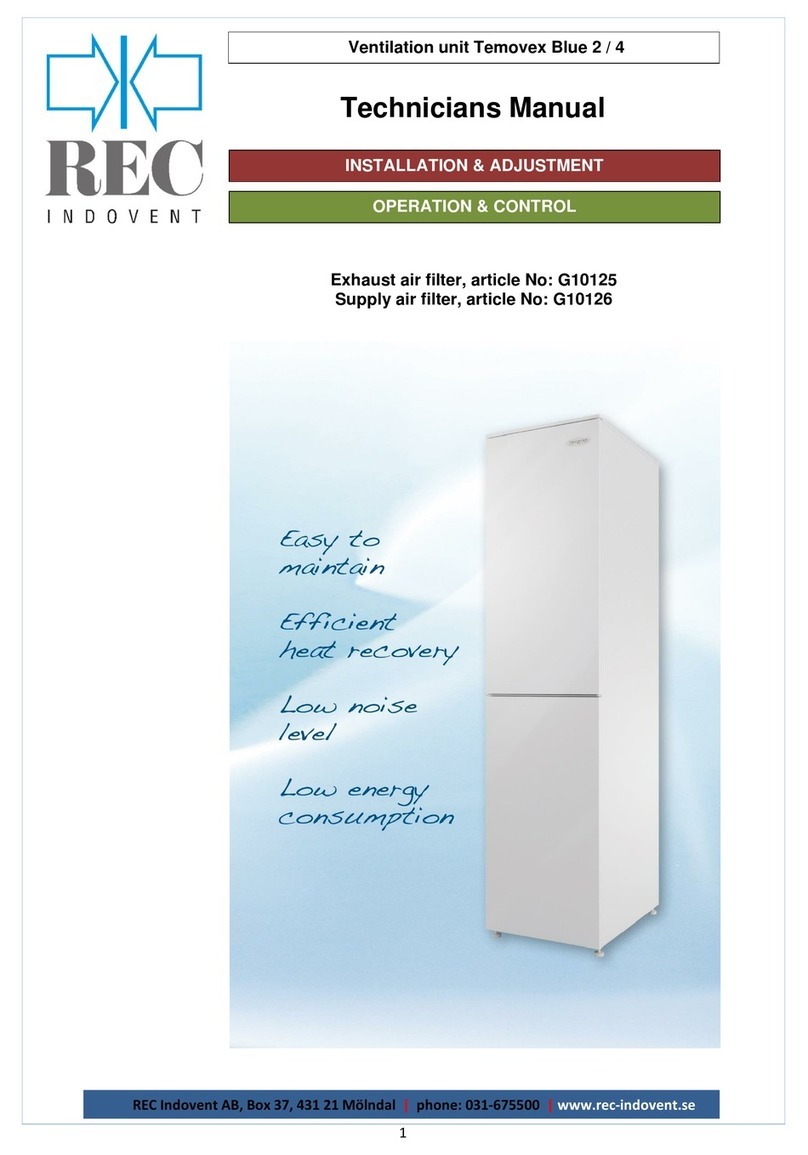
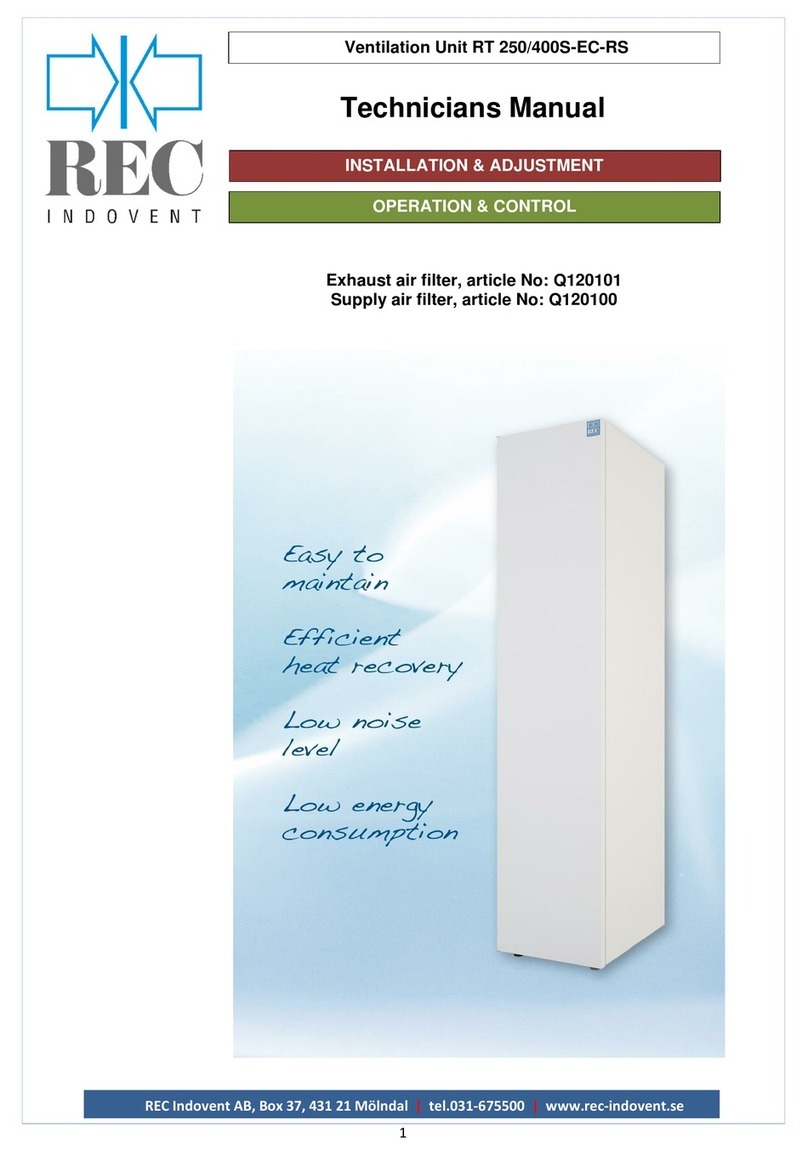
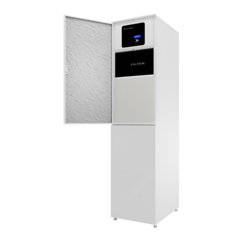
REC RT 1000S-EC-RS User manual

ggg
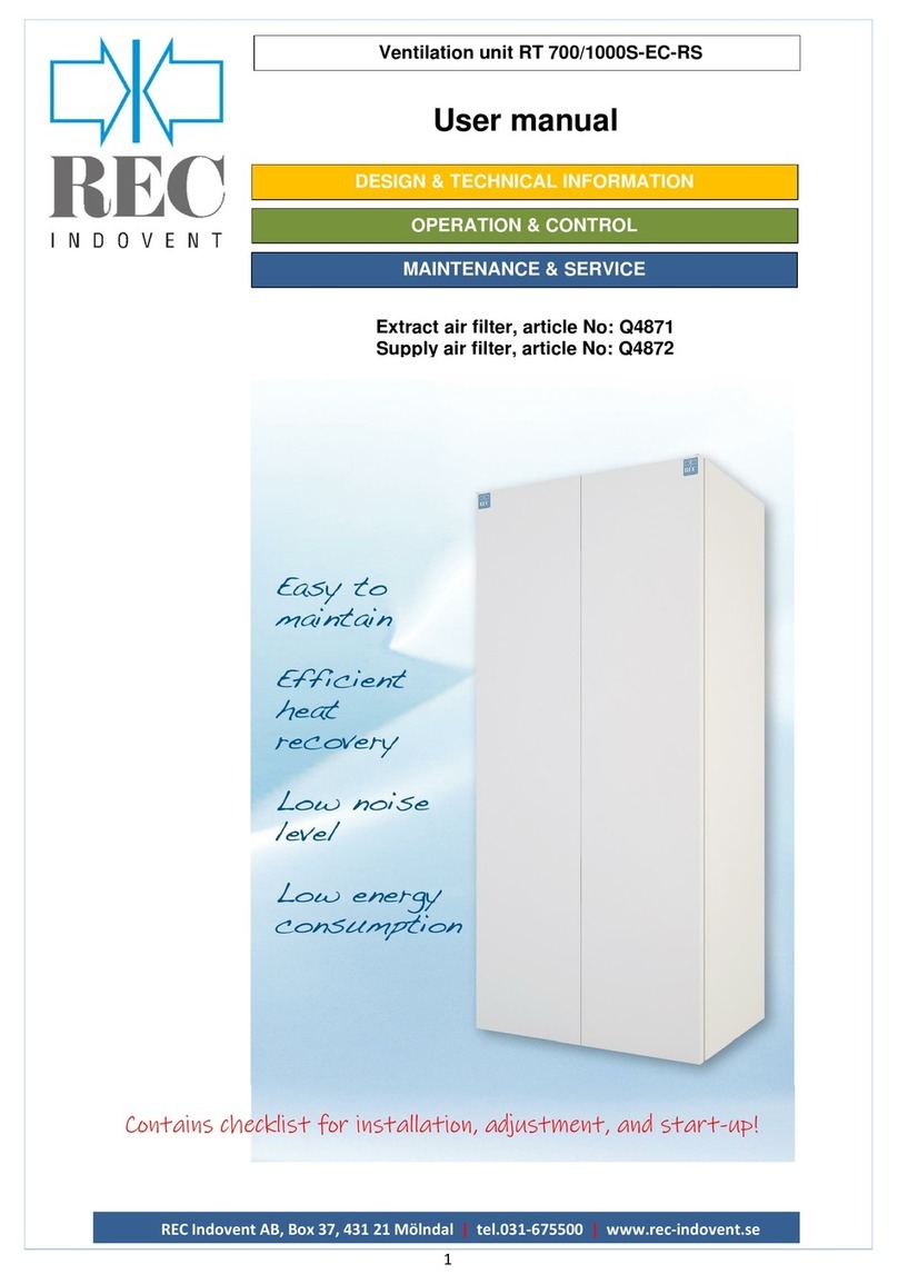
Ventilation unit RT 700/1000S-EC-RS
REC Indovent AB, Box 37, 431 21 Mölndal | tel.031-675500 |www.rec-indovent.se
1
User manual
DESIGN & TECHNICAL INFORMATION
OPERATION & CONTROL
MAINTENANCE & SERVICEMAINTENANCE & SERVICE
Extract air filter, article No: Q4871
Supply air filter, article No: Q4872

REC Indovent AB, Box 37, 431 21 Mölndal | tel.031-675500 |www.rec-indovent.se
2
CONTENTS
Ventilation Unit RT 700/1000S-EC-RS
Sid
Design & technical information
Product description 3
Casing 3
Filter, exhaust air 3
By‐pass damper 3
Fan, exhaust air 3
Fan, supply air 3
Heat exchanger 3
Filter, supply air 3
Inspection door 3
Adjustable feet 3
Condensate drain 3
Control panel 3
Reheater 3
Functional diagram ‐supply air control 4
Chiller / Cooling coil (optional) 4
Technical specification 5
Dimensions 5
Operation & control unit
Overview
Fel! Bokmärket är inte definierat.
Control unit main screen
The menu system
How to change values and settings
Menu screens, structure and contents
Fel! Bokmärket är inte definierat.
Main menu
Version
Language
Address
1. Temperature
Fel! Bokmärket är inte definierat.
Temperatures
ECO-adjusts
Control mode
Limit for cooling
2. Fan control 10
Fan control
3. Timer 11
Time and summer / wintertime
Activate timer
Time schedule
Weekend schedule
4. Inputs / Outputs 12
Status analog inputs
Universal analog inputs
Status digital inputs
Status analog outputs
Status digital outputs
Calibration of temperature sensors
5. Manual/Auto 13
Supply air regulator
Fans, bypass, heating and cooling
Digital outputs
Filter timer
6. Alarm 14
Current alarm
Alarm history
7. Load settings 14
8. Unlock functions 15
9. Authorization 15
Default user parameter setting 15
Options
Remote panel –Simple 16
Remote panel –3-way 16
Remote panel –with display 16
Stove mode 18
Maintenance & service
Cleaning 19
Changing filter 19
Cleaning the fans 19
Cleaning the heat exchanger 19
Checking the condensate drain 19
Cleaning, air diffusers 20
Cleaning the duct system 20
Checking the outdoor air intake 20
Service 20
Disposal 20

REC Indovent AB, Box 37, 431 21 Mölndal | tel.031-675500 |www.rec-indovent.se
3
DESIGN & TECHNICAL INFORMATION
Ventilation unit RT 700/1000S-EC-RS
General description
RT 700/1000S-EC-RS is designed for ventilation of
homes, offices, nurseries or other similar premises.
The Temovex unit is intended to be placed in
heated spaces such as laundry room, boiler room,
corridor or similar.
RT 700/1000S-EC-RS has everything integrated in
one unit.
The system consists in it´s standard version, of a
counterflow heat exchanger, two fans, two filters,
reheater, bypass damper and a control system.
Placeringsguide
1. Casing
2. Extract air filter (behind hatch)
3. Bypass damper motor 1
4. Extract air fan (behind hatch)
5. Supply air fan (behind hatch)
6. Heat exchanger
7. Supply air filter
8. Inspection hatch
9. Adjustable feet
10. Condensate drain
11. Control panel
12. Reheater
13. Bypass damper motor 2 (behind hatch)
1. Casing
The casing is made of hot galvanised sheet metal
with 30 mm insulation between the sheets. As a
standard, the side panels and the front are powder
coated in white. The front door has a magnetic strip
which keeps the door closed. The unit top has
sleeve connections where all ducts are connected.
2. Extract air filter
Coarse 60%, bag (art. No. Q4871)
3. Bypass damper 1
The Temovex AHU has an automatic bypass
damper which makes the air bypass the heat
exchanger whenever heat recovery is not
necessary. The bypass setting is adjusted on the
control panel. The bypass function is splitted in two
dampers with one motor each.
4. Extract air fan
The unit has low-energy fan of EC type with
integrated overheating.
5. Supply air fan
The same type as extract air fan (see point 4)
6. Heat exchanger
Temovex counterflow heat exchanger is designed
by our own staff and is the result of 30 years
experience of high efficient counterflow heat
exchangers.
The heat exchanger is made of thin aluminium
sheets, and is completely sealed beetween the
supply air and exhaust air. This is important in
order to avoid odours and other contaminants to
seeping through to the fresh air side. The heat
exchanger has no moving parts, which eliminates
wear.
7. Supply air filter
ePM1-50%, bag (art. No. Q4872).
8. Inspection hatch
When cleaning the heat exchager or controlling the
condensate drain, the Inspection hatch is opened.
(See chapter "Maintenance & service").
9. Adjustable feet
The cabinet has adjustable rubber feet.
10. Condensate drain
The Temovex unit is fitted with a condensate drain
at the bottom of the unit. This should be connected
to a drain or fed to a floor drain.
11. Control panel
All settings for fan speed, reheating, bypass etc.
are made via the control panel and the AHU's
integrated control system.
If you have added optional parts to your Temovex
AHU, these functions, too, are set via the control
panel.
12. Reheater
The unit is as standard fitted with an electric
reheater. The heater is integrated in the unit and
settings are made via the control panel.
By water heating, is the water coil delivered
separatly and shall be placed in the supply air duct
outside the unit. Even a two-way valve and valve
motor is included in the delivery from REC.
12. Bypass damper 2
(see point 3)
2
3
4
7
8
10
1
5
6
9
11
12
13

REC Indovent AB, Box 37, 431 21 Mölndal | tel.031-675500 |www.rec-indovent.se
4
DESIGN & TECHNICAL INFORMATION
Ventilation unit RT 700/1000S-EC-RS
Functional diagram
VVX Counterflow heat exchanger
ST1 Bypass damper
EVB Reheater, electricity/water
GT1 Temperature sensor, Supply air (
red sensor
)
GT11 Temperature sensor, outdoor air (
blue sensor
)
TFR Filter, Supply air (Outdoor air)
FFR Filter, Exhaust air
TF Fan, Supply air
FF Fan, Exhaust air
GT2 Over heat protection (with electric heater)
GT3 Temperature sensor, Exhaust air (
yellow sensor
)
GT7 Freeze protection (when water coil)
GT5 Temperature sensor, Extract air (
green sensor
)
Chiller (cooling coil) EKB (optional)

REC Indovent AB, Box 37, 431 21 Mölndal | tel.031-675500 |www.rec-indovent.se
5
DESIGN & TECHNICAL INFORMATION
Ventilation unit RT 700/1000S-EC-RS
Tecnical specification RT700
Electric heater Water heater
Standard Extended heater Standard
Rated electric power (total) 2150 W 2850 - 4050 W 350 W
heater 1800 W 2500 - 3700 W 2400 W1, externally
fans 2 x 170 W 2 x 170 W
Voltage/Frequency 230 V, 50 Hz 3 x 400 V, 50Hz 230 V, 50 Hz
Fuse 10 A 3 x 10 A 10 A
Water connection - DN12
Filter, supply air / exhaust air Bag: art nr. Q4872 / Bag: art nr. Q4871
Weight 195 kg
Brandklass A15
Dimensions (WxDxH) 870x620x1900 mm
Duct connections 4 x Ø200 mm
Condensate drain ¾”
Storage Temperature Range -20 …. +50ºC
Operating Temperature 0 …. +50ºC
1At water temp. 55/45 °C and 70% of maximum flow.
Tecnical specification RT1000
Electric heater Water heater
Standard Extended heater Standard
Rated electric power (total) 3190 W 5690 W 690 W
heater 2500 W 5000 W 2900 W1, externally
fans 2 x 340 W 2 x 340 W
Voltage/Frequency 3 x 400 V, 50Hz 230 V, 50 Hz
Fuse 3 x 10 A 10 A
Water connection - DN12
Filter, supply air / exhaust air Bag: art nr. Q4872 / Bag: art nr. Q4871
Weight 195 kg
Brandklass A15
Dimensions (WxDxH) 870x620x1900 mm
Duct connections 4 x Ø250 mm
Condensate drain ¾”
Storage Temperature Range -20 …. +50ºC
Operating Temperature 0 …. +50ºC
1At water temp. 55/45 °C and 70% of maximum flow.

REC Indovent AB, Box 37, 431 21 Mölndal | tel.031-675500 |www.rec-indovent.se
6
DESIGN & TECHNICAL INFORMATION
Ventilation unit RT 700/1000S-EC-RS
Dimensions RT700
Dimensions RT1000

REC Indovent AB, Box 37, 431 21 Mölndal | tel.031-675500 |www.rec-indovent.se
6
OPERATION & CONTROL
Ventilation Unit RT 700/1000S-EC-RS
General
This is a description of the basic functions that you can modify to suit your own preferences and circumstances.
The unit’s control system optimizes the function according to the settings you make. As a user of the air handling
unit it is good to know the following:
In the menus for heating and cooling, where you as a user have the possibility to make changes, the “auto mode”
is the most optimized function. Should you choose a manual setting, On or Off, the manual settings take
precedence.
Control unit
Up
Down
Right
Left
Confirm
Show alarm
Delete
Alarm Flashing There are one or more alarms that have not been acknowledged.
Steady There are one or more acknowledged alarms left.
Setting Flashing You are in a menu where it is possible to change some parameters.
Steady You are now in change position.
Menu system.
The unit’s various settings and the status of different values such as temperature etc. Can be viewed by scrolling
around in the menu system. Certain parameters and operational settings can also be changed. No basic system
configurations can be changed without authorization code (technician level).
There is a main menu that the system automatically reverts to approx. 25 minutes after the keys have been last
touched. The system also automatically logs you out after this time if you have logged in with a code.
How to change values and settings
Scroll to the desired menu using the arrow keys. Press “OK”, and the adjustable variable will start blinking.
Change with the up or down arrow keys. Moving between lateral positions is done with the right or left arrow key.
When the correct value is set, confirm with “OK”. The cursor then moves to the other alterable variable in the
same menu.
OK
C
REC TEMOVEX
Mode: Normal
Status: Heating 100%
Temp. : 21.0 °C ↓
OK
C

REC Indovent AB, Box 37, 431 21 Mölndal | tel.031-675500 |www.rec-indovent.se
7
OPERATION & CONTROL
Ventilation Unit RT 700/1000S-EC-RS
Menus and their structure
In the manual the various menus are shown looking as closely as possible as they appear on the hand terminal.
The possible jumps between the menus are also shown in the manual. More detailed information for certain
menus will, where relevant, be shown after the respective section. Begin the trek through the menus here at the
main menu.
Main menu
Mode shows current fan mode. The unit can operate in several modes, depending on temperature and
commands given to the unit etc. The options available are Stop, Low, Normal, Boost, Max, Kitchen mode, Stove
mode, Night cooling, Defrost, ECO, Fire, ECO2 and Safe mode. For more info, please see the respective mode in
the manual.
Status shows the current heating/cooling level and % output. Possible modes are Heating xx%, Bypass xx% and
Cooling xx%. If all have 0% output, ------ 0 % is shown.
Temp shows current temperature set-point.
|
}
Se sid
Fel!
€
~
Some menus may be
missing, depending on
unit configuration
€
~
~
€
~
€
|
}
|
}
|
}
|
}
|
}
|
}
|
}
|
}
~
€
~
€
~
€
~
€
|
}
REC TEMOVEX
Mode: Normal
Status: Heating 100%
Temp. : 20.0 ºC Ô
►Temperature
Fan control
Timer
In/Outputs
Temperature p. 8
Temperature
►Fan control
Timer
In/Outputs
Temperature
Fan control
►Timer
In/Outputs
Fan control
Timer
►In/Outputs
Manual/Auto
Fan control p. 10
Manual/Auto p. 13
Alarm history p. 14
Version
Version:2.1-1-00
ID number:13261274
14:04:20 08:02
Choose language
English
Address:
PLA: 254
ELA: 30
IP: -
Main menu
Sideways movement with
arrow keys right/left
Menu tree continues on
a different place in the
manual
In/Outputs
Manual/Auto
►Alarm history
Load settings
Timer
In/Outputs
►Manual/Auto
Alarm history
Timer p. 11
In/Outputs p. 12
Movement up/down with
arrow key up/down
~
€
|
}
Load settings p. 14
Manual/Auto
Alarm history
►Load settings
Unlock functions
|
}
Unlock functions p. 15
Alarm history
Load settings
►Unlock functions
Authorization
|
}
Authorization p 15
Alarm history
Load settings
Unlock functions
►Authorization

REC Indovent AB, Box 37, 431 21 Mölndal | tel.031-675500 |www.rec-indovent.se
8
OPERATION & CONTROL
Ventilation Unit RT 700/1000S-EC-RS
Version
Displays program version and control-electronics’manufacturing number. Current date and time are also shown,
which also can be changed here.
Language
Select Swedish, English or Polish.
Address
This shows the unit’s address. Can be changed.
1. Temperature.
Temperatures
Outdoor temperature is measured on incoming air at the point where the sensor is located. The sensor is placed
in the outdoor air duct as far from the unit as possible. The temperature may differ slightly from the actual outside
temperature, which may depend on the length of the duct, insulation etc.
Supply air temperature is measured in the supply air duct normally about one meter away from the unit. Supply air
is the fresh air that, after possible heating, is sent to the room.
Exhaust air temperature is measured in the exhaust air duct close to the unit. Exhaust air is the air that leaves the
room and returns to the unit.
Extract air temperature is measured in the extract air duct close to the unit. Extract air is the air that, after the heat
has been recovered, leavesthe unit and is sent out of the house.
Room temperature is measured using an external sensor located in an appropriate place in the apartment/house.
Frost protection temperature is only used with water-based heating and shows the temperature of the return water
from the heating coil. When the water temperature is too low the unit will stop, to prevent freezing of the water
coil.
ECO adjusts
ECO adjust is only used with exhaust air and room control and indicates a temperature range where heating and
cooling is not active. E.g. with ECO adjust 2 degrees and a set-point of 20 degrees, heating and cooling will not
be active between 18 and 22 degrees. ECO adjust is active when ECO is active.
Control mode
What is displayed under temperature depends on the type of control mode selected. There are five different
control modes to choose from depending on the application: a) supply air control, b) cascaded exhaust air control,
c) cascaded room control, d) outdoor compensated supply air control and e) zonal room control.
For the temperature setting and readout, select the column below corresponding to your configuration.

REC Indovent AB, Box 37, 431 21 Mölndal | tel.031-675500 |www.rec-indovent.se
9
OPERATION & CONTROL
Ventilation Unit RT 700/1000S-EC-RS
a) Supply air control b) Exhaust air control c) Room control d) Outdoor compensated supply air
control
The menu frost protection temperature is only shown when water heating is configured.
Limit for cooling
The default setting is that cooling is not activated until the outside temperature is above +20 degrees. If you want
to change this, set the outdoor temperature at which the cooling can start. There is also an adjustable hysteresis
so that the cooling does not open and close all the time if the temperature is around the set value.
Cont’d. below
|
|
|
~
€
~
€
Extract air temp. ↑
Actual: 11.5 ºC
↓
~
€
Exhaust air temp. ↑
Actual: 20.1 ºC
↓
Freeze P. temp. ↑
Actual: 8.5 ºC
↓
~
€
|
Cooling limit ↑
Outd. Temp> 20.0˚C
Hysteresis 1.0 ˚C
Cont’d. from Temperature p. 7 and above
page
|
|
|
}
|
|
}
~
€
Supply air temp ↑
Actual : 25.1 ºC
↓
~
€
~
€
Supply air temp. ↑
livingroom
Actual: 26.5 ºC
~
€
Outdoor air temp. ↑
Actual: 15.5 ºC
↓
Room temp. bedroom
Actual : 19.2 ºC
Setpoint: 19.0 ºC
ECO adjust.: 2 ºC↓
Room temp livingroom
Actual : 20.6 ºC
Setpoint: 21.0 ºC
ECO adjust.: 2 ºC↓
e) Zonal room control
Cont’d. from Temperature p. 7
|
|
}
|
|
|
}
|
|
|
}
|
|
}
|
|
~
€
~
€
~
€
Outdoor comp. Setp.↑
10 ºC = 18 ºC
15 ºC = 12 ºC
~
€
~
€
Supply air temp ↑
Actual : 25.1 ºC
↓
~
€
Supply air temp ↑
Actual : 25.1 ºC
↓
~
€
~
€
Outdoor comp. Setp.↑
-5 ºC = 23 ºC
0 ºC = 22 ºC
5 ºC = 20 ºC ↓
~
€
Supply air temp ↑
Actual : 25.1 ºC
↓
~
€
Outdoor air temp. ↑
Actual: 15.5 ºC
↓
~
€
Outdoor air temp. ↑
Actual: 15.5 ºC
↓
~
€
Outdoor air temp. ↑
Actual: 15.5 ºC
↓
|
}
Supply air temp
Actual : 25.1 ºC
Setpoint: 25.0 ºC
↓
Exhaust air temp.
Actual : 20.1 ºC
Setpoint: 20.0 ºC
ECO adjust.: 2 ºC↓
Room temp.
Actual : 20.1 ºC
Setpoint: 20.0 ºC
ECO adjust.: 2 ºC↓
OD temp.: 15.5 ºC
Supply air temp.
Act.: 25.1ºC Setp.->
Comp.SP: 12.0 ºC ↓
Outdoor comp. Setp.
-20 ºC = 25 ºC
-15 ºC = 24 ºC
-10 ºC = 23 ºC ↓

REC Indovent AB, Box 37, 431 21 Mölndal | tel.031-675500 |www.rec-indovent.se
10
OPERATION & CONTROL
Ventilation Unit RT 700/1000S-EC-RS
2. Fan control
In the operating menu you can set which mode the fans should run in. You can also see if the fans are running at
fixed speed or variable. You can also see current values and setpoints. The set values are seen within
parentheses.
Fan control
In the fan control the following six modes are always available:
·Auto: The most optimal mode. This automatically controls the temperature acc. to the built-in and
optimized algorithms of the system.
·Min flow: This forces the system to run with the set minimum flow.
·Boost: This forces the system to boost the flow. Useful if you, for example, quickly would like to air out.
·Max flow: When the fan runs with the set maximum flow.
·Kitchen flow: Used while the cooker fan is used. During kitchen flow the supply air fan normally has a
higher flow than the exhaust air fan to compensate for the air that the cooker fan extracts.
·Off: In this mode all fans are off.
The following three modes are available if the feature is installed and configured. Even if the feature is not
configured, it is visible and can be selected, but the system will after a few seconds revert to the previous
selection.
·Stove: Used when a stove is being used. In the stove mode normally the supply air fan has a higherflow
than the exhaust air fan to compensate for the air that the stove extracts.
·ECO: Only used with room control or exhaust air control when you are not home. The fans go down to
minimum flow but are gradually increasing to normal flow based on heating or cooling needs. ECO
adjust gives a temperature range around the setpoint where neither heating nor cooling is active.
·Fire: Not used on this unit!
|
}
Fan mode:Auto
Speed: Fixed Speed
SAF: 50 ( 50 ) %
EAF: 50 ( 50 ) %
Cont’d. from Fan control p. 7

REC Indovent AB, Box 37, 431 21 Mölndal | tel.031-675500 |www.rec-indovent.se
11
OPERATION & CONTROL
Ventilation Unit RT 700/1000S-EC-RS
3. Timer
In the timer setting menu, the clock can be set, and the timer configured.
Timer setting
Time and summer / wintertime
This allows you to set the time and indicate
if it should be adjusted automatically for
summer/wintertime.
Activate timer.
The timer is activated at delivery and
connected to the mode min flow.
Deactivating the timer will cause the set
times under time and weekend schedule to
be disabled as well.
Time schedule
There is an option of two periods per day.
NOTE! If you want the timer active from
e.g. Monday 20:00 until Tuesday 06:00 the
setting should be Monday Per 2: 20:00 –
24:00 and Tuesday Per 1: 00:00 –06:00.
If you have the same times recurring every
day in the week you can use the function
Monday ÚFriday.
If you want the same times on both Saturday, Sunday and all holidays (specified in the holiday settings), you can
use the macro function Saturday ÚHoliday.
Otherwise, there is a special menu for the holiday times.
Weekend schedule
Up to 24 separate holiday periods for a full year can be set. A holiday period can be any number of days, from 1
to 365, in sequence. The dates are in the format: MM:DD (Imagine that you are entering a time period from 00:00
one day until 00:00 the next day. For example, holiday June 6th is written 06:06 –06:07.) When the current date
falls within a holiday period the operating period for “Holiday”will be used.
€
~
|
|
}
|
|
}
|
}
|
}
~
€
Time: 08:59
Date: 14:02:25
Weekday: Tuesday
Summer/winter time ↓
Adjust clock
Automatically for
Summer time: Yes
Activate timer ↑
No
The timer controls:
ECO
►Schedule
Holiday schedule
Schedule
►Holiday schedule
Cont’d. from Timer p. 7
~
€
~
€
~
€
~
€
~
€
~
€
|
|
}
|
|
|
|
|
|
~
€
Holiday (mm:dd)
1: 01-01 - 01-01
2: 01-01 - 01-01
3: 01-01 - 01-01 ↓
Holiday (mm:dd) ↑
4: 01-01 - 01-01
5 01-01 - 01-01
6: 01-01 - 01-01 ↓
Holiday (mm:dd) ↑
7: 01-01 - 01-01
8 01-01 - 01-01
9: 01-01 - 01-01
↓
Holiday (mm:dd) ↑
10: 01-01 - 01-01
11: 01-01 - 01-01
12: 01-01 - 01-01
↓
Holiday (mm:dd) ↑
13: 01-01 - 01-01
14: 01-01 - 01-01
15: 01-01 - 01-01 ↓
Holiday (mm:dd) ↑
16: 01-01 - 01-01
17: 01-01 - 01-01
18: 01-01 - 01-01
↓
Holiday (mm:dd) ↑
19: 01-01 - 01-01
20: 01-01 - 01-01
21: 01-01 - 01-01 ↓
Holiday (mm:dd) ↑
22: 01-01 - 01-01
23: 01-01 - 01-01
24: 01-01 - 01-01
|
|
~
€
~
€
~
€
~
€
~
€
~
€
~
€
|
|
|
|
|
|
}
|
}
|
}
Monday->Friday:
Per. 1: 08:00- 17:00
Per. 2: 00:00- 00:00
Monday:
Per. 1: 08:00- 17:00
Per. 2: 00:00- 00:00
↓
Tuesday: ↑
Per. 1: 08:00- 17:00
Per. 2: 00:00- 00:00
↓
Wednesday: ↑
Per. 1: 08:00- 17:00
Per. 2: 00:00- 00:00
↓
Thursday: ↑
Per. 1: 08:00- 17:00
Per. 2: 00:00- 00:00
↓
Friday: ↑
Per. 1: 08:00- 17:00
Per. 2: 00:00- 00:00
↓
Saturday: ↑
Per. 1: 08:00- 17:00
Per. 2: 00:00- 00:00
↓
Saturday->Holiday:
Per. 1: 00:00- 00:00
Per. 2: 00:00- 00:00
Sunday: ↑
Per. 1: 00:00- 00:00
Per. 2: 00:00- 00:00
↓
Public holiday: ↑
Per. 1: 08:00- 17:00
Per. 2: 00:00- 00:00

REC Indovent AB, Box 37, 431 21 Mölndal | tel.031-675500 |www.rec-indovent.se
12
OPERATION & CONTROL
Ventilation Unit RT 700/1000S-EC-RS
4. Inputs/Outputs
In this menu the status of all inputs and outputs can be controlled.
Sensors can also be calibrated.
Status analog inputs.
This shows all the system’s current temperatures.
Universal analog inputs.
The universal inputs can be configured for different purposes
such as temperature or 0-10V input. Can be eg room sensors,
anti-freeze sensors or pressure sensors, etc. Current values of
resp. entrance are displayed. Temperature in ˚C and pressure
in Pa.
“Not active”means the input is not used (nothing is configured
for the input).
Status digital inputs.
“On”means 24V is applied on the input and the mode
configured for the input is active.
“Off”means the input is at 0V and the mode is not active.
The alarm inputs may have status ok or Alarm.
Status analog outputs.
This shows the current voltage on the
output.
Status digital outputs.
“On”means the output is active and “Off”consequently means
the output is not active.
Calibration of temperature sensors.
This gives the possibility to adjust the value for the
temperature sensors up or down. (Set an offset value). May,
for example, be used to synchronize the old normal
thermometer with the system temperature. Input the difference
here and they will display the same values.
|
}
|
|
|
|
}
~
€
~
€
DI4 SA fan :Ok ↑
DI5 EA fan :Ok
DI6 Not active :Off
DI7 Overheat p.:Ok
↓
Analog inputs
►Digital inputs
Analog outputs
Digital outputs
DI1 Not active Off
DI2 Not active Off
DI3 Not active Off
↓
~
€
DI8 FilterAla:Ok ↑
|
|
}
AO1 SA fan: 5.0 V
AO2 EA fan: 5.0 V
AO3 Heater: 10.0V
AO4 Chiller: 0.0 V
Analog inputs
Digital inputs
►Analog outputs
Digital outputs
~
€
|
|
|
}
~
€
DO1 BP opening :On
DO2 BP closing :Off
DO3 PWM heat :Off
DO4 Not active :Off↓
Digital inputs
Analog outputs
►Digital outputs
Calibrate sensors
DO5 CP heater :On↑
DO6 KAVK :Off
DO7 ULS :Off
~
€
|
~
€
|
}
|
UAI1: 24.7ºC K: 0.0↑
UAI2: NaN ºC K: 0.0
UAI3: NaN ºC K: 0.0
UAI4: NaN ºC K: 0.0
AI1: 18.3ºC K: 0.0
AI2: 24.6ºC K: 0.0
AI3: 23.2ºC K: 0.0
AI4: 13.3ºC K: 0.0 ↓
Digital inputs
Analog outputs
Digital outputs
►Calibrate sensors
~
€
~
€
|
|
}
AI1 OD temp 10.0ºC
AI2 SA.temp 20.0ºC
AI3 EA temp 21.3ºC
AI4 EXT temp 14.0ºC↓
UAI1 Not act 0.0 ↑
UAI2 Not act 0.0
UAI3 Not act 0.0
UAI4 Not act 0.0 ↓
►Analog inputs
Digital inputs
Analog outputs
Digital outputs
Cont’d from Inputs/Outputs p. 7
AO1 SA fan: 5.0 V
AO2 EA fan: 5.0 V
AO3 Heat/Coo: 10.0 V
AO4 BypassVP: 0.0 V↓
Alternative display when
selecting VP

REC Indovent AB, Box 37, 431 21 Mölndal | tel.031-675500 |www.rec-indovent.se
13
OPERATION & CONTROL
Ventilation Unit RT 700/1000S-EC-RS
5. Manual/Auto
In Manual/Auto a great number of functions may be controlled manually,
which is very useful for commissioning and troubleshooting.
All possible menus are shown on the side. In a real application all of
these are never present simultaneously since there are not that many
outputs, allowing for all to be configured at the same time, and also
since perhaps certain functions are not needed in the application in
question and thus are not configured.
If an output is manually controlled the normal control is rendered
ineffective. Therefore, an alarm is generated as soon as any output is
set to any other mode than Auto.
Supply air regulator
The supply air regulator signal may be manually varied between 0 and
100%. The output signal for the temperature control will follow if it is in
the Auto mode.
Fans, bypass, heating and cooling
The operating mode of the fans can be controlled manually 0-100% as
can heating, bypass and cooling. For the bypass damper the level of
opening of the damper is also shown.
Digital outputs
All configured digital outputs such as ULS, KAVK, CP etc. can be set to
Auto, On or Off, (or similar words indicating the two possible conditions
of a digital signal).
Filter timer
The filter timer is also controlled here. You can set an interval between
the filter changes of 6 –18 months. In the menu the number of months
remaining before the filters should be changed is shown. NOTE! This
value is only updated once per day. I.e. if “Interval”is changed the “Time
remaining”will not be changed before the next day.
When it is time to change filter, this is indicated on the display on the row
“Mode”by having the existing text alternate with the text “Change filter”.
After the filter change, you should reset the timer in this menu.
NOTE! Even if you change filters prematurely (before the prompt
appears on the display), you should reset the timer, to ensure the correct
time interval for the next filter change.
|
€
~
|
|
|
|
|
~
€
~
€
~
€
~
€
~
€
~
€
~
€
~
€
~
€
|
|
}
|
|
|
|
|
~
€
SA controller
Auto
Man. output: 0
↓
Supply air fan ↑
Auto
Man. output: 0
↓
Exhaust air fan ↑
Auto
Man. output: 0
↓
Heater ↑
Auto
Man. output: 0 %
↓
PreHeat electric ↑
Auto
Man. output: 0 %
↓
Duct heater ↑
Auto
Man. output: 0 %
↓
BP / By-pass damper↑
Auto
Man. output: 0
Pos.: 100% open
↓
Chiller ↑
Auto
Man. output: 0
↓
ULS/OD air damper ↑
Auto
↓
KAVK / Cond. boiler↑
Auto
↓
CP/Circ. pump ↑
Heater: Auto
↓
Cont’d from Manual/Auto p. 7
CP/Circ. pump ↑
Chiller: Auto
↓
€
~
Filter timer ↑
Interval: 12 months
Remains: 10 months
Set zero: No

REC Indovent AB, Box 37, 431 21 Mölndal | tel.031-675500 |www.rec-indovent.se
14
OPERATION & CONTROL
Ventilation Unit RT 700/1000S-EC-RS
6. Alarm
Current alarm
Current alarm and its status can be seen by pushing the red button.
Here the alarms may also be acknowledged, blocked or unblocked (allow alarm).
An alarm that was confirmed, but where the error was not fixed will show as a confirmed error in the menu. As
soon as the error is fixed it will disappear from the menu (since it is already confirmed).
You can also block an alarm in order to run the unit despite the alarm. NOTE! This you should not be done
without proper knowledge, since it may cause danger and in worst case damage to property.
Alarm history
This shows the 21 latest alarm activities. E.g. when the alarm was triggered, when it was confirmed and/or reset
etc. No alarms may be confirmed, blocked etc here.
7. Load settings
This reloads previously saved settings into the DUC, or if you have never saved anything the default settings.
All settings are loaded except date and time.
|
~
€
|
Sensor error OD
Temp
28 Feb 15:20 Klass:A
↓
Any menu
Back to previous menu
El.heat. overheated↑
28 Feb 14:34 Klass:A
El.heat
. overheated
►Acknowledge
Block
OK
|
}
~
€
28 Feb 15:20 A ↑
El.heat. overheated
Activated ↓
Cont’d. from Alarm history p.7
28 Feb 13:50 A ↑
Sensor error OD
temp
Acknowledge ↓
|
}
Load saved
Settings:
No
Cont’d from Load settings p. 7

REC Indovent AB, Box 37, 431 21 Mölndal | tel.031-675500 |www.rec-indovent.se
15
OPERATION & CONTROL
Ventilation Unit RT 700/1000S-EC-RS
8. Unlock functions
Used if you add functions afterwards. Please contact your supplier!
9. Authorization
This is where a technician with proper access rights may log in to adjust the system and if necessary, change
certain parameters.
Default user parameters setting.
Parameter Default Setting Parameter Default Setting
Language Swedish Summertime Yes
Address 254, 30 Activate timer No
Setpoint supply air temp.
control 19 ˚C The timer controls Min flow
Setpoint exhaust air control 21 ˚C Schedule Monday-Friday 8-17, 0-0
Setpoint room control 21 ˚C Holiday schedule 0-0
Outdoor compensated
setpoint 25, 24, 23, 23, 22, 20, 18, 18 Holiday 01-01 –01-01
Eco adjustment 2 Manual/Auto (all) Auto
Cooling limit Outd. Temp> 20.0˚C
Hysteresis: 1.0 ˚C Filter timer Interval 12 months
Fan Control Auto
|
}
|
}
►Log in
Log in
State code: ****
Cur.level:None
Cont’d from Authorization p. 7
|
}
Input code: 0
Cont’d from Unlock functions p. 7

REC Indovent AB, Box 37, 431 21 Mölndal | tel.031-675500 |www.rec-indovent.se
16
OPERATION & CONTROL
Ventilation Unit RT 700/1000S-EC-RS
Options
Remote panel –Simple (art.no. Q100446)
Remote panel - Simple (TG-R4) contains a temperature sensor and a set-point knob.
The unit is used as a room thermostat, but also allows you to shift the set-point within
a certain range.
The normal set-point is entered on the ventilation unit display and based on this value
the set-point may be adjusted using the knob on the Remote Panel –Simple plus or
minus a few degrees.
The adjusted set-point is shown on the main menu of the unit display.
Remote panel –Simple uses analog transmission of values to the unit.
Remote panel –3-way (art.no. Q100543)
Simple remote panel for easy activation of normal mode, minimum mode (ECO) and
forced mode.
Even potential alarms (red LED) are indicated on the panel.
Remote panel –with display (art.no. Q101299)
Remote panel –with display is the most advanced remote panel.
This also contains a temperature sensor and can be used as a
room thermostat. It also has a display and some keys allowing
you to see different temperatures and set them. You can also set
the fan speed and see a lot of other information. In addition, it
has an “away key”built in.
Temperature set-point display.
Normally (when you have not touched any key for the last 10 s) the set-point is shown on the display at the same
time as the indoor temperature symbol and the house symbol are turned on.
Change of the temperature set-point.
Pushing once on the menu selection key will cause the set-point symbol to start flashing and the possibility is
given to change the set-point using the adjustment keys. The value is saved when no keys have been touched for
10 s and the display reverts to showing the set-point.
Remote panel - Simple
Remote panel –3-way
Away mode
Adjustment keys
Menu selection
Remote panel –with display
Set-point symbol
Fan speed Kitchen/Stove
Fan symbol
Indoor temp symbol,
outdoor temp symbol
and house symbol
respectively
Away mode
BP open
Temperature

REC Indovent AB, Box 37, 431 21 Mölndal | tel.031-675500 |www.rec-indovent.se
17
OPERATION & CONTROL
Ventilation Unit RT 700/1000S-EC-RS
Display of actual temperature.
Pushing once more (within 10 s) on the menu selection key will turn off the set-point symbol, the indoor
temperature symbol will start flashing and the display will show the actual value. The adjustment keys have no
function in this case. When the keys have not been touched for 10 s, the display will revert to showing the set-
point.
Display of the outdoor temperature.
Pushing once more (within 10 s) on the menu selection key will turn off the indoor temperature symbol. At the
same time the outdoor temperature symbol is turned on and the outdoor temperature is shown in the display. The
adjustment keys have no function in this case. When the keys have not been touched for 10 s, the display will
revert to show the set-point.
Fan speed:
Pushing once more (within 10 s) on the menu selection key will turn on the fan symbol and the fan speed as well
as MAN or AUTO. The fan symbol will start flashing and the fan speed can be changed by stepping around to the
desired mode (min, normal, forced or max) with the adjustment keys. The modes correspond to the setting in the
menu selection Mode on the main display and a change onthe remote panel will also be shown on the main
panel.
The symbol MAN indicated that the unit is using a different mode than AUTO.
It may be that the unit is in a speed between min and max and normal and forced respectively due to forced or
safe mode. The symbol fan speed will show the actual fan mode according to the following:
·At fan speed 0 no box filled.
·< normal mode leftmost box turned on
·= normal mode the two leftmost boxes are turned on
·> normal mode but < = Forced mode the three leftmost boxes are turned on
·= max mode all boxes turned on
If the unit on the main display is run manually using Hand/Auto the fan speed will not be changed when changed
on the remote panel. What happens is that the changes are made on the symbols of the display and also on the
main panel in the menu Mode but are not implemented on the fans until you exit the manual mode in Hand/Auto.
The new setting is saved when you continue with menu selections or after not having touched the keys for 10 s
and the display reverting to showing the set-point.
Kitchen/Stove.
The symbol kitchen/stove is turned on when the unit is operated in the stove or kitchen mode.
Away mode/ECO mode.
Pressing the away key will turn off the away mode symbol and the unit changes to ECO mode.
An additional press will make the mode revert.
The mode assumes that ECO is activated on the unit under system.
Bypass.
The bypass symbol is turned on when the bypass is > 0 % open.
Cool.
COOL is turned on if cooling is selected under system and the cooling valve is open > 0 %.
Heat.
HEAT is turned on if the controller requests > 0 % heating.
Alarm.
SERVICE is turned on if there is an unconfirmed alarm on the unit.
Off.
OFF is turned on if the unit is in the off mode.

REC Indovent AB, Box 37, 431 21 Mölndal | tel.031-675500 |www.rec-indovent.se
18
OPERATION & CONTROL
Ventilation Unit RT 700/1000S-EC-RS
Stove mode
Extent.
The stove mode must be activated from the factory to make the stove mode work.
In addition to the software configuration a momentary switch is included in the function (To
connect and configure please see the Technician Manual).
The stove mode means reduced exhaust air and increased supply air during the initial time
after the stove has been lit. It means that the cooling is blocked so that you do not cool out
the nice heating from the stove.
Start of stove timer.
Pushing once on the switch starts the stove mode and a timer starts counting down at the same time. If you regret
the choice you can easily turn off the mode with a new push on the switch.
Stove indication.
That the stove mode is active is indicated on the indicator lamp in the switch.
For more extensive functional description see the TechnicianManual under the section 7.15 I/O configuration.
REC 21-07-02 (pgm. ver. 2.4-1-00)

REC Indovent AB, Box 37, 431 21 Mölndal | tel.031-675500 |www.rec-indovent.se
19
MAINTENANCE & SERVICE
Ventilation Unit RT 700/1000S-EC-RS
Cleaning
Keep the unit clean for maximum performance and
long service life. The filters should be changed at
least once a year or more frequently if necessary.
The fans and heat exchangers must be cleaned
according to the instructions below.
Changing filters
The Temovex unit has two filters, exhaust air filter
and outdoor air filter (fresh air).
The filters should be changed at least once a year
or more often if necessary. The filter should not be
washed but replaced with new ones.
The unit has a filter guard that alerts when the filter
is to be replaced.
New filters can be ordered from REC Indovent AB at
www.rec-indovent.se or phone 031-675500.
The unit must not be operated without the
intended original filters. Operation without filters
seriously affects the performance of the unit and
can damage the unit's fans and heat exchangers.
The unit operates even if the filters are dirty, but the
performance would be less good, energy
consumption increases and heat recovery
decreases.
Cleaning the fans
·Switch of the power.
·Open the unit's doors.
·Remove both covers.
·Disconnect the fan's electric plug and pull out
the fan. (Clean one fan at a time).
·Clean the impeller using a brush or
compressed air.
·Refit the fans in reverse order.
·Refit the covers.
·Close the doors.
·Turn on the power.
NOTE! The fans must under no
circumstances be cleaned under running
water!
Cleaning the heat exchanger
·Switch of the power.
·Open the unit's doors.
·Remove both fans (see above).
·Open the inspection hatches by
the bottom of the unit.
·Remove the red plug at the
bottom of the unit, the condensate
drain.
·Flush the heat exchanger with hot
water.
NOTE! If the unit is fitted with a condensate
evaporator unit (KAVK), a wet vac should be
used to deal with the rinse water.
A degreasing agent may be required if the heat
exchanger is very dirty.
NOTE! The agent must be of a type which is
not aggressive to aluminium. Alkaline
detergents with caustic ammonia and alike
must never be used, since they have a
corrosive action on aluminium, i.e. ruin the heat
exchanger.
·Refit the red plug (On the same side of the unit
as the filters).
·Refit the inspection hatches.
·Refit the fans in reverse order.
NOTE! Make sure the fan motors are not/do
not get wet when restarting the unit. If wet, this
could be fatal!
·Refit the covers.
·Close the unit doors.
·Turn on the power using the main switch.
Checking the condensate drain
·Open the unit's doors.
·Open the inspection hatches at the bottom of
the cabinet.
·Make sure the drain is not
blocked. This can be done
by pouring some water into
the bottom of the unit.
NOTE! On the side which does not have a red
plug.
·If the drain is jammed, try to remove the
obstruction. If need be, call a plumber.
·Refit the inspection hatches.
·Close the unit doors.
Cleaning the air diffusers
The building's air diffusers must be
cleaned regularly in order to maintain
correct ventilation. Use a dry cloth
and/or a small brush to reach inside the
opening of the diffuser. It can also be
taken down if that makes cleaning
easier. Use a duster or a dry cloth to
remove possible dirt marks in the ceiling
around the device.
NOTE! The air diffuser's setting must not be
changed. If taken down, each diffuser must be
returned to its original place.
!
!
!
!
This manual suits for next models
1
Table of contents
Other REC Fan manuals