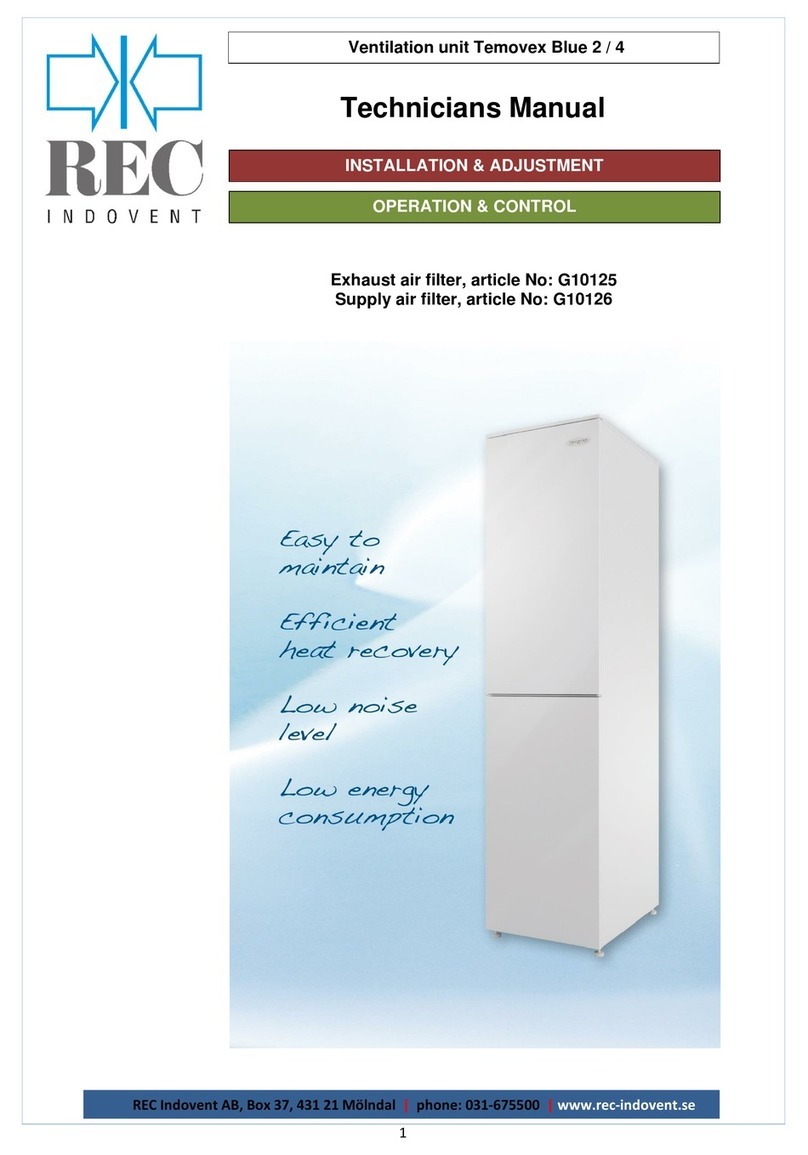
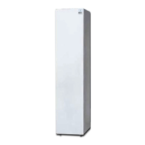
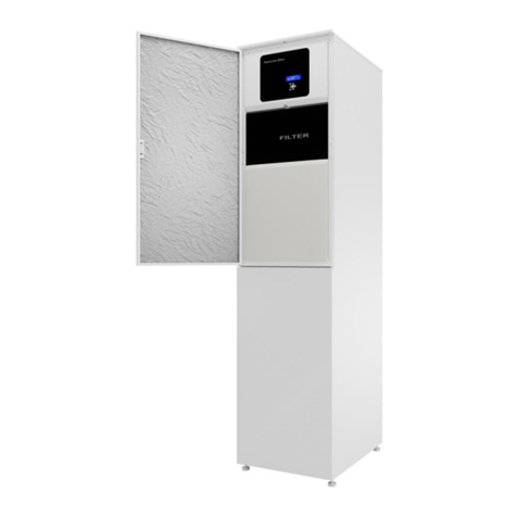
REC RT 400S-EC-RS User manual

Ventilation Unit RT 250/400S-EC-RS
REC Indovent AB, Box 37, 431 21 Mölndal | tel.031-675500 |www.rec-indovent.se
1
Exhaust air filter, article No: Q120101
Supply air filter, article No: Q120100
INSTALLATION & ADJUSTMENT
OPERATION & CONTROL
Technicians Manual

CONTENTS
Ventilation Unit RT 250/400S-EC-RS
REC Indovent AB, Box 37, 431 21 Mölndal | tel.031-675500 |www.rec-indovent.se
2
Page
Installation & Adjustment
Safety and Security 3
Receipt of Delivery 3
Installation 3
Mounting 3
Installation of Water-Resistant Substrate 3
Anti-tip Protection 3
Condensate Drain 3
The Duct System 3
Silencing 4
Placing of Temperature Sensors 4
Insulation 4
Duct cover for AHU top 4
Open Fireplace 4
Power connection 4
Access to connection terminals 5
Circuit Diagram 6
Terminal Description 7
Connection Options 8
Fireplace Button
ULS, KAVK, CP Heat Etc.
Modbus
Remote Panel –With Display
Remote Panel –3-Position
Remote Panel –Easy (TG-R4)
Internet
Operation & Control
2. Menu table configuration 11
2.1. Control function 17
Control Functions
Cascade Control
Setpoint Adjustment
Room Sensors
2.2. Demand Control 17
Activate
Temperature control
CO2 control
Moisture control
2.3. Fan Setup 18
Fan control
Setting fan speeds
Fan delay
2.4. Temperature control 18
Setting the controllers
What are P and I
Supply air controller
Room controller
Exhaust air controller
Zone control
Pre-heat controller
2.5. PID output 19
Heating, Bypass, Cooling
Pre-heater
Duct heater
2.6. ECO/ECO2 19
ECO-mode
ECO2-mode
ECO adjustment
Fault safe mode
Activate ECO2 cooling
Temp diff.
Temperature conditions for forcing
Screen view at boosting and ECO
Fan curve at ECO/ECO2
2.7. Heater 21
Type of heater
Electric heater
Water heater
Anti-freeze function
Exercise of valve
2.8. Defrosting 22
Stop defrost
During stop defrost
2.9. Bypass 22
Bypass dumper´s running time
Outdoor temp. limit of open
Activate ramptime
2.10.Cooling recovery 23
2.11.Night cooling 23
Extended running time.
Boost cooling
Conditions night cooling
2.12.Forced cooling 24
2.13.Timer 24
2.14.KAVK (Condensation boiler) 24
2.15.I/O configuration 25
Analog inputs
Digital inputs
Priority order
Timer
Stove mode
Digital outputs
Inverting digital outputs
Analog outputs
2.16.Modbus 26
2.17.TCP/IP 27
2.18.EXOline address 27
2.19.Remote Panel 27
2.20.Setpoint Adjustment TG-R4 27
2.21.Activate Exhaust fan 27
2.22.Filter Timer 27
2.23.Cloudigo 27
2.24.Save Settings 27
2.25.User Menu 27
2.26.Zones 28
Enable Zones
Remote Panel Configuration
Temperature Menus
2.27.Change Alarm Class 28

REC Indovent AB, Box 37, 431 21 Mölndal | tel.031-675500 |www.rec-indovent.se
3
INSTALLATION & ADJUSTMENT
Ventilation Unit RT 250/400S-EC-RS
Safety and Security
Please read this manual carefully. Pay special
attention to the safety text marked with the
exclamation mark above.
Receipt of Delivery
Check that the number of packages matches the
consignment note and that there is no transport
damage. The ventilation unit must be stored
indoors.
If possible, the unit should be kept lying down
to minimize the risk of personal injury in case of
overturning. Pay special attention to this if children
are nearby.
Installation
Work performed by the layman can impair the
performance of the ventilation unit and result in
injury to person or property. Incorrectly adjusted
units will not achieve the desired benefits such as
adequate air quality and maximized energy savings.
The unit is heavy. Edges and corners that you do
not usually come in contact with can be sharp. Use
gloves when moving the unit.
Keep an eye on children. An unassembled
unit can easily tip over under abnormal loads.
Mounting
The ventilation unit is mounted upright in the utility
room, laundry room or the like. The unit is designed
to stand in frost-free space, which is extra important
when using condensate drains.
Ensure that there is a stable and level surface on
the installation site. If the unit is placed on wooden
floors or other moisture-sensitive materials, the unit
must be placed on a water-resistant substrate (type
Temovex Art. No. Q100490) to prevent marks and
moisture damage if possible. leakage or
condensation. (See next paragraph for assembly.)
It is an advantage if the unit can be placed at least
10 mm away from the wall. This is to minimize the
risk of muffler noise. We recommend that the walls
of surrounding rooms also be soundproofed. These
precautions should be maintained despite the fact
that Temovex units are generally very quiet. The
unit is equipped with adjustable rubber feet and well
balanced fans, to avoid vibration.
The unit should be installed in such a way that it is
easy to access for maintenance and inspection.
Make sure the door at the front can be fully opened.
The unit must be placed so that it cannot be flushed
with water during operation. As an option, the unit
can be provided with protection that allows the
installation to withstand IP class X5.
Installation of Water-Resistant Substrate
Q100490
The ventilation unit is often installed in a corner or
next to another cabinet. In this case, there are two
sides to support the Water-Resistant Substrate. The
third side is created with suitable wooden strip
which is attached to the floor with eg double-sided
adhesive tape, glue, screw etc. Cut lower the base
to a width of 500mm (440mm + 30mm fold in each
side). Cut equally on each side. Otherwise, follow
the instructions that come with the underlay.
Anti-tip Protection Q100428
If it is judged that there is a risk that the unit may tip
forward, there is a tip guard (art. no. Q100428) as
an option. This is then fixed to the back of the unit
and screwed during installation in the wall behind
the unit.
Condensate Drain
The unit is equipped with a condensation drain at
the bottom of the unit. This should be connected to
a drain or routed to a floor well. Make sure that the
condensation line is placed far enough down in the
floor well, otherwise it can draw cold air from it. The
condensation line does not
need to be fitted with a
water trap. The
condensate drain has to be
connected when the unit is
installed. If the unit is
equipped with condensation boiler (KAVK) no
external connection is needed.
The Duct System
Ducts and duct details should be made of an age-
resistant material that is also easy to clean inside.
For shorter adaptations between, for example a roof
hood and the duct system, a flexible duct called
"Drasuten" can advantageously be used.
Tumble dryers and drying cabinets must not be
connected directly to the duct system. “Dragavbrott”
shall be used.
!
!
!

REC Indovent AB, Box 37, 431 21 Mölndal | tel.031-675500 |www.rec-indovent.se
4
INSTALLATION & ADJUSTMENT
Ventilation Unit RT 250/400S-EC-RS
Silencing
Silencers dimensioned for the installation should be
fitted both for the supply air and exhaust air, either
directly onto the Temovex unit, or to the duct system
as close to the unit as possible. Under certain
conditions, silencers on the outdoor air duct as well
as extract air duct may be necessary.
Placing of Temperature Sensor
The four duct sensors are color-marked at both
ends as follow:
Outdoor air = blue
Supply = red
Extract = green
Exhaust = yellow
At delivery, all temperature sensors are electrically
connected to the control system. The extract and
exhaust air sensors are also pre-mounted in the
AHU's respective air ducts.
The outdoor air and supply air sensors must be
mounted during installation in respective duct.
The supply air sensor should be placed in the
supply air duct, at least 0,6 m from the heater to
avoid direct heat radiation, and after the first bend if
possible, where the temperature is more
homogeneous.
The outdoor air sensor should be placed as far from
the unit as possible (as far as the cable allow).
Remember to seal the holes carefully.
If the unit is equipped with a water battery, the anti-
freeze sensor is also pre-mounted and connected.
If a room sensor is used, it should be placed approx.
1,8 m above the floor in the living room, prefereably
on an interior wall.
Insulation
Outdoor air and extract air ducts in heated spaces
must be insulated against condensation along their
entire length, using an insulation sleeve minimum
PE30. The diffusion barriers are sealed with
ventilation tape.
Supply and exhaust air ducts in warm rooms do not
need to be insulated against condensation,
however, heat insulation may be appropriate.
Decided on a case by case basis.
If the supply and exhaust air ducts are placed in
cold or unheated spaces, they shall be heat
insulated. If insulation mat is used, a total thickness
of at least 120 mm should be achieved. The
insulation should be shared in two layers with
overlapping joints.
If placement in loose wool, the cover layer over the
ducts should be at least 150 mm.
Duct cover for AHU top
The lacquered, 2-piece cover hides the ducts at the
top of the Temovex unit. The cover is telescopic and
will fit ceiling heights between 2,30 - 2,70 m. We
recommend a gap of 5 mm between ceiling and
duct cover to avoid anytransfer of vibrations.
1. Measure the
distance from the top
of the unit (without
duct cover) to the
ceiling.Assemble the
two pieces on a flat
surface/floor, and
ensure that the
height will allow a
gap of approx. 5 mm
to the ceiling.Use the
enclosed 4 self-
tapping screws to
make the holes in
the upper (smaller)
cover plate. Use the 4 white screws to join the
two cover plates.
2. Put the duct cover on top of the unit, placing
the screw-heads in the "key" holes. Fix the
cover onto the unit by sliding it backwards
some 5 mm (see
picture).If the duct
cover is mounted
onto an existing
unit, the pop rivets
at the unit top have
to be replaced by
screws.
3. Whenever you need access to the
upper part of the Temovex unit,
the duct cover is lifted off in one
piece (point 2 above, but reverse
order)
Open Fireplace
Most modern fireplaces and the like have a
separate outdoor air connection which provides the
combustion chamber with combustion air. If this is
not available/possible, a separate outdoor air
diffuser needs to be fitted. The stove consumes
between 150-300 m3/h.
To make it easier to start the stove (ignition, the
fireplace door is open), the Temovex unit can be
equipped with the option "stove function".
Power connection
The AHU is provided with a grounded plug.
Connect the plug to an earthed 1-phase socket
(230 VAC / 10 A).
Connection at the top of the unit.

REC Indovent AB, Box 37, 431 21 Mölndal | tel.031-675500 |www.rec-indovent.se
5
INSTALLATION & ADJUSTMENT
Ventilation Unit RT 250/400S-EC-RS
Access to connection terminals
The bottom card can now be reached and set up with
required functions.
After the installation of functions is done, re-fit the DUC in
reverse order.
The printed circuit board screen print.
DUC
Remove the DUC
from the PCB by
squeezing each
top of the four
spacers with a
pair of pliers.
Squeeze one at a
time and ease the
DUC out at the
same time.
The DUC is now
attached to the
board by 2 ribbon
cables only.
The spring locks
on the plugs of
the DUC's ribbon
cables make it
easy to loosen
them from the
circuit board.

REC Indovent AB, Box 37, 431 21 Mölndal | tel.031-675500 |www.rec-indovent.se
6
INSTALLATION & ADJUSTMENT
Ventilation Unit RT 250/400S-EC-RS
Circuit Diagram

REC Indovent AB, Box 37, 431 21 Mölndal | tel.031-675500 |www.rec-indovent.se
7
INSTALLATION & ADJUSTMENT
Ventilation Unit RT 250/400S-EC-RS
Description of terminal blocks
General
Joining of circuits is made on the bottom circuit
board. To access the circuit board, remove the DUC
(see previous page).
Texts on the circuit board show where to connect
what. All terminals have a Jxx No. and a small
triangle on pin 1.
When in the following text for example J26/1,2 is
stated, it means that the function should be
connected to terminal J26, pin 1 and 2.
Where appropriate, the signal is marked on the
board.
Room sensor (Terminal J6/1,2)
If room sensor is to be used, keep in mind that room
control must be selected in the configuration of the
system.
External cooling (Terminal J8/1,2,3)
The system also has ability to handle an external
water-cooling battery, e.g. natural cooling from
boreholes.
The cooling battery is controlled via an external
valve (0 - 10 V).
Reheater water (Terminal J7)
Two alternative is possible, so called wax-actuator
(controlled by PWM-signal) or motor-actuator (0-
10V signal).
(The cable may already be connected upon
delivery)
Temperature sensors (Terminal J9)
Temperature sensors (PT1000) for
outdoor air
,
supply air
,
extract air
and
exhaust air
are already
connected at delivery.
Freeze protection (Terminal J10/1,2)
In order to prevent freezing of the water battery in
the case of water heating, a freeze protection
sensor (temperature sensor) is placed on the return
line from the water battery.
Modbus (Terminal J12)
Terminal for possible modbus communication.
ECO Remote (Terminal J100)
Terminal for connecting a remote control (optional)
with among other things alarm indication and a
switch for ECO mode.
NOTE! When using ECO Remote, DO6 must be
configured for Normal flow, DO7 for Sum alarms
and DI2 to ECO.
Fans (Terminal J13 and J14)
Connection terminals for the fans. These are
already connected at delivery.
By-pass (Terminal J28)
Connection terminal for the by-pass damper. The
cable is already connected at delivery.
Optional terminal for by-pass (Terminal J29)
Extra connection terminal for by-pass damper
(some AHU models).
Ext.1, Ext.2 and Ext.3 (Terminals J23 to J25/1,2)
There is, as an option, the possibility to connect
three external switches which at closing change the
fan speeds according to the choices made during
configuration. Appropriate flows are preset but can
be changed by a qualified installer via the control
panel.
For available choices see section "Operation &
Control".
Start/stop (Terminal J26/1,2)
An external switch for "Start/stop" can be
connected. The switch does not make the unit
powerless. It just makes the AHU stop running.
If this function is used, the jumper J34 should be
moved to mode OFF.
Optional terminal for filter guard (Terminal J21)
For some of the larger AHU models only.
Relay outputs (Terminals J19, J20)
The system has 4 identical relay outputs which can
be configured to various functions. The
configuration in the circuit diagram above is just one
example, others is possible. To see which options
are available, please turn to chapter "Operation &
control".
A condensation boiler (KAVK), if any, is already
connected at delivery.
Mains voltage (Terminals J15, J16, J17)
230VAC, 50Hz
Chassis (Terminal J18)
Ground connection of chassis.
Electric heater, power supply (Terminal J5/2,3)
Pin 2 phase, pin 3 neutral (blue).
Electric heater, control signals (Terminal J4)

REC Indovent AB, Box 37, 431 21 Mölndal | tel.031-675500 |www.rec-indovent.se
8
INSTALLATION & ADJUSTMENT
Ventilation Unit RT 250/400S-EC-RS
Connection Options
Connection of Fireplace Button (24V)
Connection of ULS, KAVK, CP-heating etc. (230V)
Connection according to above, on any output DO4-DO7 and selected output configure to selected function.
Blue
Brown
Yellow/Green
ULS
KAVK
CP-heating
The selected digital output is
configured to fireplace mode.
In this example, DO6 is selected.
The selected digital input is
configured to fireplace mode.
In this example, DI2 is selected.

REC Indovent AB, Box 37, 431 21 Mölndal | tel.031-675500 |www.rec-indovent.se
9
INSTALLATION & ADJUSTMENT
Ventilation Unit RT 250/400S-EC-RS
Connection Modbus
Connect Modbus on Terminal J12 pin 3 and 4.
Connection Remote Panel –With Display
You cannot have both Modbus and remote panel. To connect a remote panel with a display, Modbus
communication must be deactivated. Contact REC.
Remote panel with display can be connected according to below.
Remote Panel PCB
10 J8/1
11 J8/3
42 J12/3
43 J12/4
Connection Remote panel –3-position
Connect the socket to terminal 100
(ECO Remote).
Connect blue cable to terminal J8/1
(24VAC).
Connect pink cable to terminal
J26/1.
Please note! The configuration of
inputs and outputs should be in this
order for the display to work:
DO6 - Normal, DO7 - Alarm, DI1 -
ECO, DI2 - Forc
Modbus
A
B

REC Indovent AB, Box 37, 431 21 Mölndal | tel.031-675500 |www.rec-indovent.se
10
INSTALLATION & ADJUSTMENT
Ventilation Unit RT 250/400S-EC-RS
Connection Remote panel –Easy (TG-R4)
Remote - PCB
panel
1 J6/1
2 J6/2
3 J10/3
4 J10/4
Connection Internet (Cloudigo)
Connect an internet cable to DUC as on picture.
Pull out the cable through a suitable lead-through on the top of the unit.

REC Indovent AB, Box 37, 431 21 Mölndal | tel.031-675500 |www.rec-indovent.se
11
OPERATION & CONTROL
Ventilation Unit RT 250/400S-EC-RS
For initial information see the User Manual!
Start at Authorization and log in as Technician with code 2222.
2. Menu table configuration Not relevant for RT 250/400 (should not be selected)
Parameter Standard setting Changed setting of this unit
2.1. Control function
2.1.1. Control function SA control ☐ODT comp. SA control, ☐Casc. room control,
☐Casc. EA control
2.1.1.1. When cascade control max/min SA setpoint
Max 52,0 ˚C __________ ˚C (0 - 150 ˚C)
Min 12,0 ˚C __________ ˚C (0 - 150 ˚C)
2.1.2. Setpoint adjust.
Min -3,0 ˚C __________ ˚C (-10,0 –0,0 ˚C)
Max 3,0 ˚C __________ ˚C (0,0 –10,0 ˚C)
TG-R4 (Display of current setpoint)
Ext. display (Display of current setpoint)
2.1.3. Room sensor (displayed at
Casc. room control and Remote panel) Only analog input ☐Only external display, ☐Mean value
2.2. Demand control (only displayed with SA control)
2.2.1. Activate
Temp.-control No ☐Yes
2.2.1.1. Extract air temp. control
Setpoint. 22,0 ˚C __________ ˚C (0 - 50 ˚C)
Control mode Cool ☐Heat
2.2.1.1.1. PI-settings temperature
P-band 33,0 ˚C __________ ˚C
I-time 100,0 sec __________ sec
CO2-control No ☐Yes
2.2.1.2. CO2-control
Setpoint 1000 ppm __________ ppm (0 –2000 ppm)
2.2.1.2.1. PI-settings CO2
P-band 100 ppm __________ ppm
I-time 100,0 sec __________ sec
Humidity-control No ☐Yes
2.2.1.3. Humidity-control
Setpoint 60 % RH __________ % RH (0 –100 % RH)
2.2.1.3.1. PI-settings humidity
P-band 33,0 % RH __________ % RH
I-time 100,0 sec __________ sec
2.3. Fan setup
2.3.1. Fan control
Fan control Fixed Speed ☐Pressure, ☐Flow
2.3.2. Fan speeds
2.3.2.1. Supply air fan
Min 20 % __________ %
Normal 50 % __________ %
Boost 80 % __________ %
Kitchen 80 % __________ %
Stove 80 % __________ %
Night cool 50 % __________ %
Max 100 % __________ %
Fire 0 % __________ %
2.3.2.1.1. Delay SA fan
Start 0 sec __________ (0 –3600 sec)
Stop 60 sec __________ (0 –3600 sec)
Ramp time 1.00 V/s __________ V/s
2.3.2.2. Extract air fan
Min 25 % __________ %
Normal 55 % __________ %
Boost 85 % __________ %
Kitchen 20 % __________ %
Stove 20 % __________ %

REC Indovent AB, Box 37, 431 21 Mölndal | tel.031-675500 |www.rec-indovent.se
12
OPERATION & CONTROL
Ventilation Unit RT 250/400S-EC-RS
Night cool 55 % __________ %
Max 100 % __________ %
Fire 100 % __________ %
2.3.2.2.1. Delay EA fan
Start 0 sec __________ (0 –3600 sec)
Stop 0 sec __________ (0 –3600 sec)
Ramp time 1.00 V/s __________ V/s
2.4. Temperature control
2.4.1. SA control
P-band 33,0 ˚C __________ ˚C
I-time 100,0 sec __________ sec
2.4.2. Room control (is displayed if Casc. room control is selected)
P-band 100,0 ˚C __________ ˚C
I-time 300,0 sec __________ sec
2.4.3. EA control (is displayed if Casc. EA control is selected)
P-band 100,0 ˚C __________ ˚C
I-time 300,0 sec __________ sec
2.4.4. SA control Livingroom (is displayed if Zone control is selected)
P-band 33,0 ˚C __________ ˚C
I-time 100,0 sec __________ sec
2.4.5. Room control Livingroom (is displayed if Zone control is selected)
P-band 100,0 ˚C __________ ˚C
I-time 300,0 sec __________ sec
2.4.6. Preheat control (is displayed if Pre Heater is selected)
P-band 33,0 ˚C __________ ˚C
I-time 100,0 sec __________ sec
2.5. PID output (no settings)
2.5.1. PID output
Heating xxx %
By-pass xxx %
Cooling xxx %
2.5.2. PID output preheater (is displayed if preheater is selected)
Damper xxx %
Electric xxx %
2.5.3. PID output duct heater (is displayed if zone control is selected)
Heating xxx %
Setpoint change x,x ˚C
2.6. ECO/ECO2 (is displayed if ECO and/or ECO2 is selected under system settings)
2.6.1. Activate ECO2 cooling (is
displayed if ECO2 is selected
under system settings)
Yes ☐No
2.6.2. Temp. diff.
Heat 1,0 ˚C __________ ˚C (0 –10,0 ˚C)
Cool 2,0 ˚C __________ ˚C (0 –10,0 ˚C)
Dead band 0,5 ˚C __________ ˚C (0 –1,0 ˚C)
2.6.3. Temp diff for increase to boost
Heat: TL>FL+ 1,0 ˚C __________ ˚C (0 –10,0 ˚C)
Cool: TL<FL- 1,0 ˚C __________ ˚C (0 –10,0 ˚C)
2.6.4. Alarm delay
Warning temperature deviation 300 sec __________ sec
2.7. Heater
2.7.1. Type of heater Electric ☐Water (PWM), ☐No heater, ☐Water (0-10V)
2.7.1.1. When selecting "Electric"
Period 60 sec __________ sec (0 –600 sec)
2.7.1.2. When selecting "Water (PWM)"
Frost protection
Start temp. 13,0 ˚C __________ ˚C (13 –50,0 ˚C)
Exercise valve No ☐Yes
Day Monday __________ (Monday - Sunday)
Hour 0 __________ (0 - 23)
Valve runtime 180 sec __________ sec
Period 10 sec __________ sec (0 –600 sec)
Reg. area 67 - 87 % __________ - __________ % (0 –100 %)
2.7.1.3. When selecting "Water (0-10V)"
Frost protection 13,0 ˚C __________ ˚C (13 –50,0 ˚C)

REC Indovent AB, Box 37, 431 21 Mölndal | tel.031-675500 |www.rec-indovent.se
13
OPERATION & CONTROL
Ventilation Unit RT 250/400S-EC-RS
Start temp.
Dead band valve 0,5 % __________ % (0 –50,0 %)
Exercise valve No ☐Yes
Day Monday __________ (Monday - Sunday)
Hour 0 __________ (0 - 23)
Valve runtime 180 sec __________ sec
2.8. Defrost
2.8.1. Exhaust temperature 0,0 ˚C ☐__________ ˚C (-30,0 –10,0 ˚C)
Defrost time 5 min ☐__________ min
Delay 3 h ☐__________ h (0 - 24 h)
2.8.2. During stop defrost (if electric reheater)
Bypass 0 % ☐__________ % (0 –100 %)
SAF 0 % ☐__________ % (0 –100 %)
Heat 0 % ☐__________ % (0 –100 %)
During stop defrost (if water reheater)
Bypass 100 % ☐__________ % (0 –100 %)
SAF 0 % ☐__________ % (0 –100 %)
Heat 100 % ☐__________ % (0 –100 %)
2.9. Bypass
2.9.1. Bypass damper’s
running time 45 s __________ s (0 –300 s)
2.9.2. Bypass outdoor temp. limit for open
Outdoor temp.. > 0,0 ˚C __________ ˚C
Hysteresis 1,0 ˚C __________ ˚C
2.9.3. Activate ramptime Only defrosting ☐Not active, ☐Always active
Ramptime: 180 s __________ s
2.10. Cold air recovery
Recover cold air Yes ☐No
Conditions to start recover
Outdoor temp. >EA + 2,0 ˚C __________ ˚C (0,0 –20,0 ˚C)
2.11. Night cooling
Activate night cooling No 22:00 –06:00 ☐Yes __________ - __________ (00:00 –24:00)
After time 4 hours __________ h (0 –24 h)
Reset No ☐Yes
2.11.1. Conditions night cooling
Day OD >22 ˚C __________ ˚C (0 –30 ˚C)
OD temp 10 ˚C __________ ˚C (0 –30 ˚C)
Room temp >18 ˚C __________ ˚C (10 –30 ˚C)
2.12. Forced cooling
Activate forced cooling on SA
control No 00:00 –24:00 ☐Yes __________ - __________ (00:00 –24:00)
Setpoint Exhaust air 28,0 ˚C __________ ˚C (10,0 –40,0 ˚C)
Hysteresis 1,0 ˚C __________ ˚C
2.13. Timer
The timer controls Min flow ☐ECO, ☐Boost, ☐Max, ☐AHU On/Off
2.14. KAVK/Condensation boiler (is displayed if “KAVK”is configured on any digital output)
Start temp 5,0 ˚C __________ ˚C (0,0 –30,0 ˚C)
Stop temp 10,0 ˚C __________ ˚C (0,0 –30,0 ˚C)
2.15. I/O configuration (ATTENTION! if the function corresponding to the desired selection is not configured, the selection returns when you leave the menu)
2.15.1. Analog inputs
UI1 Not active ☐Room sensor, ☐Frost protection sensor, ☐TG-R4,
☐Duct heater sensor, ☐Option temp 1,
☐Option temp 2, ☐Option temp 3, ☐Option temp 4,
☐Temp after Exch, ☐SAF Pressure, ☐EAF Pressure,
☐Exch. Pressure, ☐CO2, ☐Humidity
UI2 Not active ☐Room sensor, ☐Frost protection sensor, ☐TG-R4,
☐Duct heater sensor, ☐Option temp 1,
☐Option temp 2, ☐Option temp 3, ☐Option temp 4,
☐Temp after Exch, ☐SAF Pressure, ☐EAF Pressure,
☐Exch. Pressure, ☐CO2, ☐Humidity

REC Indovent AB, Box 37, 431 21 Mölndal | tel.031-675500 |www.rec-indovent.se
14
OPERATION & CONTROL
Ventilation Unit RT 250/400S-EC-RS
UI3 Not active ☐Room sensor, ☐Frost protection sensor, ☐TG-R4,
☐Duct heater sensor, ☐Option temp 1,
☐Option temp 2, ☐Option temp 3, ☐Option temp 4,
☐Temp after Exch, ☐SAF Pressure, ☐EAF Pressure,
☐Exch. Pressure, ☐CO2, ☐Humidity
UI4 Not active ☐Room sensor, ☐Frost protection sensor, ☐TG-R4,
☐Duct heater sensor, ☐Option temp 1,
☐Option temp 2, ☐Option temp 3, ☐Option temp 4,
☐Temp after Exch, ☐SAF Pressure, ☐EAF Pressure,
☐Exch. Pressure, ☐CO2, ☐Humidity
2.16.1.4. CO2 (is displayed if CO2 is selected on any analog input)
0.0 V –>0 ppm __________ V -> __________ ppm
10.0 V –>1200 ppm __________ V -> __________ ppm
2.16.1.5. Humidity (is displayed if Humidity is selected on any analog input)
0.0 V –>0.0 %RH __________ V -> __________ %RH
10.0 V –>100.0 %RH __________ V -> __________ %RH
2.15.2. Digital inputs (*the function must be activated from the factory to be selected)
DI1 AHU On/Off ☐Not active, ☐Min flow, ☐Boost flow, ☐Max flow,
☐Kitchen mode*, ☐ECO*, ☐Stove mode*,
☐Fire input*, ☐Fire damper*, ☐Normal,
☐Filter guard fire, ☐Smoke detector error*,
☐T (connected to timer)
DI2 Not active ☐Min flow, ☐Boost flow, ☐Max flow, ☐Kitchen mode*,
☐ECO*, ☐Stove mode*, ☐Fire input*, ☐Fire damper*,
☐AHU. On/Off, ☐Normal, ☐Filter guard fire,
☐Smoke detector error*, ☐T (connected to timer)
DI3 Not active ☐Min flow, ☐Boost flow, ☐Max flow, ☐Kitchen mode*,
☐ECO*, ☐Stove mode*, ☐Fire input*, ☐Fire damper*,
☐AHU. On/Off, ☐Normal, ☐Filter guard fire,
☐Smoke detector error*, ☐T (connected to timer)
DI6 Not active ☐Min flow, ☐Boost flow, ☐Max flow, ☐Kitchen mode*,
☐ECO*, ☐Stove mode*, ☐Fire input*, ☐Fire damper*,
☐AHU. On/Off, ☐Normal, ☐Filter guard fire,
☐Smoke detector error*, ☐T (connected to timer)
DI7 (is only displayed if a heat
source other than electricity is
selected)
Not active ☐Min flow, ☐Boost flow, ☐Max flow, ☐Kitchen mode*,
☐ECO*, ☐Stove mode*, ☐Fire input*, ☐Fire damper*,
☐AHU. On/Off, ☐Normal, ☐Filter guard fire,
☐Smoke detector error*, ☐T (connected to timer)
DI4 TF omr. ☐SA fan EC
DI5 TF omr. ☐EA fan EC, ☐Not active
Alarm delay SA 30 sec __________ sec
Alarm delay EA 30 sec __________ sec
2.15.2.1. Timer
Time 0 hour, ☒0 min ________ h (0 –24 h), ________ min (0 –59 min)
Edge Hi ☐Low
2.15.2.1.1.Stove timer (is displayed if "Stove mode" is configured on any digital output)
Ignite time 15 min __________ min (0 –30 min)
After time 12 hours __________ h (0 –24 h)
2.15.3. Digital outputs (*the function must be activated from the factory to be selected)
DO3 (only displayed if heater
"water 0-10V" or "no heater" is
selected)
Not active ☐KAVK, ☐ULS, ☐Sum alarms, ☐CP heater,
☐CP chiller, ☐Normal flow, ☐Fire damper, ☐Stove,
☐Section hatch, ☐Sum alarm A, ☐Sum alarm B,
☐Sum alarm C, ☐Smoke detector
DO4 Not active ☐KAVK, ☐ULS, ☐Sum alarms, ☐CP heater,
☐CP chiller, ☐Normal flow, ☐Fire damper,
☐PWM preheat, ☐Stove, ☐Section hatch,
☐Sum alarm A, ☐Sum alarm B, ☐Sum alarm C,
☐Smoke detector
DO5 Not active ☐KAVK, ☐ULS, ☐Sum alarms, ☐CP heater,
☐CP chiller, ☐Normal flow, ☐Fire damper,
☐PWM preheat, ☐Stove, ☐Section hatch,
☐Sum alarm A, ☐Sum alarm B, ☐Sum alarm C,

REC Indovent AB, Box 37, 431 21 Mölndal | tel.031-675500 |www.rec-indovent.se
15
OPERATION & CONTROL
Ventilation Unit RT 250/400S-EC-RS
☐Smoke detector
DO6 Not active ☐KAVK, ☐ULS, ☐Sum alarms, ☐CP heater,
☐CP chiller, ☐Normal flow, ☐Fire damper,
☐PWM preheat, ☐Stove, ☐Section hatch,
☐Sum alarm A, ☐Sum alarm B, ☐Sum alarm C,
☐Smoke detector
DO7 Sum alarm ☐Not active ☐KAVK, ☐ULS, ☐CP heater,
☐CP chiller, ☐Normal flow, ☐Fire damper,
☐PWM preheat, ☐Stove, ☐Section hatch,
☐Sum alarm A, ☐Sum alarm B, ☐Sum alarm C,
☐Smoke detector
2.15.3.1. Invert DO
DO3 No ☐Yes
DO4 No ☐Yes
DO5 No ☐Yes
DO6 No ☐Yes
DO7 No ☐Yes
2.15.4. Analog outputs
AO3 Heating 0.0 V –10.0 V __________ V -__________ V
AO4 Cooling 0.0 V –10.0 V __________ V -__________ V
2.16. Modbus
Modbus communication Active ☐Not active
Modbus TCP On ☐Off
Modbus Address 1 __________
Baud rate 9600 bps ☐4800 bps, ☐14k4 bps, ☐19k2 bps, ☐28k8 bps,
☐38k4 bps, ☐57k6 bps, ☐76k8 bps, ☐115k2 bps
Format 801 ☐8N2, ☐8E2, ☐802, ☒8N1, ☐8E1
2.17. TCP/IP
DHCP Yes ☐No
Current IP ->
IP 192.168.001.234 __________
Current subnet mask 255.255.255.000 __________
Current gateway 192.168.001.001 __________
Current DNS 192.168.001.001 __________
2.18. EXOline address
Address
PLA 254 __________
ELA 30 __________
2.19. External display
Activate external display No ☐Yes
Port 2 __________
2.19.1. Setpoint adjustment
Max 3,0 ˚C __________ ˚C (0,0 –10,0 ˚C)
Min -3,0 ˚C __________ ˚C (-10,0 –0,0 ˚C)
2.20. Setpoint adjustment TG-R4
Setpoint adjustment with TG-R4
Activate No ☐Yes
2.21. Activate EA-fan
Activate EA-fan Yes ☐No
2.22. Filter timer
Activate Filter timer Yes ☐No
Number of days since start (Current value)
__________
2.23. Cloudigo
Activate Cloudigo No ☐Yes
2.24. Save settings
Save current settings No ☐Yes
2.25. User menu
Temperature On ☐Off

REC Indovent AB, Box 37, 431 21 Mölndal | tel.031-675500 |www.rec-indovent.se
16
OPERATION & CONTROL
Ventilation Unit RT 250/400S-EC-RS
Mode On ☐Off
Timer On ☐Off
In/outputs On ☐Off
Hand/Auto On ☐Off
Alarm history On ☐Off
Load settings On ☐Off
2.26. Zones
Activate 2 Zones No ☐Yes
2.26.1. Configure external display
Configure Livingroom (Connect ONE external display)
Configure No ☐Yes
Configure Bedroom (Connect ONE external display)
Configure No ☐Yes
2.27. Change Alarm Class
Alarm
Sensor error OD temp A ☐B, ☐C, ☐Inactive
Sensor error SA temp A ☐B, ☐C, ☐Inactive
Sensor error EXT temp A ☐B, ☐C, ☐Inactive
Sensor error EA temp A ☐B, ☐C, ☐Inactive
Sensor error Room temp A ☐B, ☐C, ☐Inactive
Sensor error FRP temp A ☐B, ☐C, ☐Inactive
Freeze protection alarm A ☐B, ☐C, ☐Inactive
Supply fan failure C ☐A, ☐B, ☐Inactive
Extract fan failure C ☐A, ☐B, ☐Inactive
Preheat damper manual C ☐A, ☐B, ☐Inactive
Electric heater overheated A ☐B, ☐C, ☐Inactive
Filter guard DI8 A ☐B, ☐C, ☐Inactive
Chiller manual C ☐A, ☐B, ☐Inactive
Heater manual C ☐A, ☐B, ☐Inactive
By-pass manual C ☐A, ☐B, ☐Inactive
ULS manual C ☐A, ☐B, ☐Inactive
KAVK manual C ☐A, ☐B, ☐Inactive
P1-heating manual C ☐A, ☐B, ☐Inactive
P1-cooling manual C ☐A, ☐B, ☐Inactive
SA fan manual C ☐A, ☐B, ☐Inactive
EA fan manual C ☐A, ☐B, ☐Inactive
SA controller manual C ☐A, ☐B, ☐Inactive
Internal battery failure A ☐B, ☐C, ☐Inactive
Filter alarm Inactive ☐A, ☐B, ☐C
Fire damper alarm A ☐B, ☐C, ☐Inactive
Fire alarm A ☐B, ☐C, ☐Inactive
Sensor error TG-R4 A ☐B, ☐C, ☐Inactive
Warning low supply temp C ☐A, ☐B, ☐Inactive
Preheat electric manual C ☐A, ☐B, ☐Inactive
Supply air temp low A ☐B, ☐C, ☐Inactive
Duct heater manual C ☐A, ☐B, ☐Inactive
Sensor error duct heater A ☐B, ☐C, ☐Inactive
Sensor error temp. after exch. A ☐B, ☐C, ☐Inactive
Defrost failed A A ☐B, ☐C, ☐Inactive
Defrost failed B B ☐A, ☐C, ☐Inactive
Hatch manual C ☐A, ☐B, ☐Inactive
Autocalibration not finished C ☐A, ☐B, ☐Inactive
Fire indication B ☐A, ☐C, ☐Inactive
Smoke detector error B ☐A, ☐C, ☐Inactive

REC Indovent AB, Box 37, 431 21 Mölndal | tel.031-675500 |www.rec-indovent.se
17
OPERATION & CONTROL
Ventilation Unit RT 250/400S-EC-RS
2.1. Control function
2.1.1. Control functions
Selectable features:
·SA control: The temperature is regulated by the SA sensor only.
·ODT comp. SA control:The temperature is regulated as a function of the SA sensor and OD sensor.
·Casc. Room control: The temperature is regulated as a function of the room sensor and SA sensor.
·Casc. EA control: The temperature is regulated as a function of the EA sensor and SA sensor.
2.1.1.1. When cascade control max/min SA setpoint
This function is only active when cascade room control and cascade exhaust air control is used.
The rooms desired set point is set on the room sensor if room control and on the EA sensor if EA control. The
system calculates a new supply air (SA) set point based on the control error. In the extreme case (if large control
error) this could be very high (or low), which could generate too cold or hot supply air, which could feel
uncomfortable. It is possible to limit the SA set point both up and down.
2.1.2. Set point adjust
The menu "Set point adjust" is used together with room sensor with set point adjust
included, like Remote panel –Easy (TG-R4). Hear you can set the setting range for
the setpoint value adjustment. With the knob in center position (0 adjustment), the
setpoint on the main display is the one that applies.
Current adjustment for TG-R4 can be seen in the display on line 3.
The current setpoint on the remote panel can be seen in line 4.
2.1.3. Room sensor
If there is more than one room sensor, where one is connected to the analog input (an
ordinary simple standard sensor or e.g., remote panel - Simple (TG-R4)) and the other is a
serial remote panel with built-in sensor connected to port 1 or 2, it is possible to choose from
where the actual value should be taken. This menu is only displayed if room control is used.
2.2. Demand control
Demand control means that the fans regulate between normal flow and forced flow due to temperature, CO2 or
humidity or a combination thereof. The extract air sensor is used as the temperature sensor. CO2 and humidity
sensors are connected to an analog input 0-10V. If you choose a combination of sensors, it is the regulator that
wants the highest fan speed that "wins".
2.2.1. Activate
Menu for activating the various demand control functions.
2.2.1.1. Temperature control
Menu for setting the temperature setpoint
If temperature control is selected, it is possible to choose if the demand control shall be connected to heating or
cooling.
NOTE! Check that supply air and exhaust air setpoints do not contradict each other. Normally you choose a
supply air setpoint that is a few degrees below what you want as room temperature. Demand setpoint should be
the desired temperature in the room.
2.2.1.1.1. PI-settings temperature
Setting of control parameters.
2.2.1.2. CO2-control
Menu for setting the CO2 setpoint
2.2.1.2.1. PI-settings CO2
Setting of control parameters.
Remote panel - Easy
Remote panel –With display

REC Indovent AB, Box 37, 431 21 Mölndal | tel.031-675500 |www.rec-indovent.se
18
OPERATION & CONTROL
Ventilation Unit RT 250/400S-EC-RS
2.2.1.3. Humidity-control
Menu for setting the humidity setpoint
2.2.1.3.1. PI-settings RH
Setting of control parameters.
2.3. Fan setup
2.3.1. Fan control
Selectable features:
·Fixed Speed: The fan is running with a fixed %-value of the maximum speed.
2.3.2. Fan speeds
Menu group for fan speeds. When adjusting, you can balance the correct flows by changing the setting for resp.
fan.
2.3.2.1. Supply air fan
In this menu, you set the setpoints for the speeds of the supply air fan, corresponding to the various operating
modes.
Fan speed night cooling
The value for night cooling is, on delivery, the same as normal mode. If the value for normal mode is changed, the
value for night cooling will be changedtoo, unless the value for night cooling is actively set to something else.
To get them synchronized again, set the night cooling value at the same value as normal mode.
2.3.2.1.1. Delay SA fan
Menu for setting the supply air fan start and stop delay.
2.3.2.2. Extract air fan
Menu like 2.3.2.1. but for the exhaust fan.
2.3.2.2.1. Delay EA fan
Menu like 2.3.2.1.1. but for the exhaust fan.
2.4. Temperature control
In this menu group, you can adjust the control parameters for the different temperature controllers. All controllers
are of the PI type with adjustable P-band and I-time.
Setting the controllers
In most cases, it works with the default setting, but if you see a need for it, you can adjust it.
Warning! At the same time, an incorrect setting can cause the system to function very badly.
It is the same supply air regulator in all three cases above. A change follows if you change the control function.
What is P and I?
P-band is the temperature change needed to move the actuator from closed to fully open. A small P-band (= large
gain) causes an unstable system. A small temperature change on the sensor generates maximum heat and
provides large overshoots. A large P-band (low gain) on the other hand provides smaller overshoots but will take
longer before the correct value is reached.
Including an integrator (I-value) in the control loop will provide smaller overshoots. The gain decreases the closer
the set point comes.
2.4.1. SA control
The supply air regulator is indirect acting, i.e., the output signal increases with decreasing temperature.
With the correct P and I parameter, the temperature at the supply air sensor will be kept constant at the set
setpoint.
2.4.2. Room control

REC Indovent AB, Box 37, 431 21 Mölndal | tel.031-675500 |www.rec-indovent.se
19
OPERATION & CONTROL
Ventilation Unit RT 250/400S-EC-RS
The room regulator works together with the supply air regulator in so-called cascade regulation. A deviation in
room temperature compared to the set point generates a shift of the operating point of the supply air regulator so
that the deviation is eliminated.
2.4.3. EA control
The exhaust air regulator works together with the supply air regulator in so-called cascade regulation. A deviation
in exhaust air temperature compared to the set point generates a shift of the operating point of the supply air
controller so that the deviation is eliminated.
2.4.4. SA Control Livingroom
See section 2.4.1.
2.4.5. Room control Livingroom
See section 2.4.2.
2.4.6. Preheat control
Preheater control parameters.
2.5. PID output
2.5.1. PID output (Heating, Bypass, Cooling)
Here the output from the SA controller is
displayed, divided between the three outputs
cooling, bypass and heating.
The output from the SA controller 0-100% is
divided between the outputs as follow.
2.5.2. PID output preheat
Menu showing pre-heat output.
2.5.3. PID output duct heater
The line "Heating" shows the equipment of the duct heater. When this has reached 100% and the living room still
has not reached its setpoint, the bedroom's setpoint is shifted (increased) little by little, causing the unit's built-in
heater to increase so that the living room's setpoint is reached. Howmany degrees the displacement is now can
be seen on the last line.
2.6. ECO/ECO2
ECO-mode
·ECO can be used together with all control functions.
·ECO saves energy when nobody is at home. The fans go down to minimum flow.
·ECO means that the fans, when they go on min. flow, increase speed up to normal flow, to carry more
heat or cool if min. flow cannot hold the set point.
·ECO-boosting together with cooling works even without cooler. The AHU takes cold air through the
bypass only and will cool as far as possible.
·ECO-mode can be activated in different ways, either by a manual switch connected to a digital input or
automatically according to a time schedule. ECO can also be activated manually in the mode menu.
ECO2-mode
·ECO2 is used only together with EA and room -control.
·ECO2 means that the fans increase the speed more than with ECO alone. They increase all the way to
boost-flow, to carry more heat or cool if actual flow cannot hold the set point.
·ECO2-boosting together with cooling, works even without cooler. The AHU takes cold air through the
bypass only and will cool the room as far as possible.
·ECO2 works just as well in ECO mode (when nobody home), as it does when you are at home and the
unit is running at normal flow.
·ECO2-boosting together with cooling can be turned off, if you want boosting together with heating only.
Controller output
(PID
-
output)
Cooling By-pass Heating
0
–
32%
100
–
0%
100%
0%
32
–
64%
0%
100
–
0%
0%
64 - 66% 0% 0% 0%
66
-
100%
0%
0%
0
-
100%

REC Indovent AB, Box 37, 431 21 Mölndal | tel.031-675500 |www.rec-indovent.se
20
OPERATION & CONTROL
Ventilation Unit RT 250/400S-EC-RS
ECO-adjusting
·ECO-adjusting is only active with EA- and room-control.
·ECO-adjusting needs ECO to be activated.
·ECO-adjusting indicates a temperature range where heat and cool is inactive. E.g., with ECO-adjust 2°C
and a set temp of 20°C, the heat and cool will be inactive between 18°C and 22°C.
Safe mode
·To make it possible to heat/cool with air, it is necessary that enough heat/cool is available through the
heater/cooler.
·Safe mode is an extra protection function that blocks the boosting, in the event of lack of heating /
cooling media. The aim is to bring as little unwanted cooling / heating to the apartment as possible
during a possible unit failure, but still have some ventilation. The fans regulate down towards minimum
flow, pending the return of heating / cooling media. It is a continuous regulation, which means that if
there is not enough heat/cool, the fans speed up only as much as the heat/cool allows to give a positive
heat/cool supplement.
·In the absence of heating media, the unit gives the alarm "Warning low supply air temp". See further at
the point alarm delay below.
·Safe mode is only active in exhaust and room control and if ECO and / or ECO2 are installed at the
factory. The setting menus for this are displayed only if ECO and / or ECO2 are installed.
2.6.1. Activate ECO2 cooling.
If you wish to use ECO2 cooling, change No to Yes.
2.6.2. Temp. diff.
In this menu, you set how fast the fans shall increase to boost flow. There is a dead band, before the fans start to
increase at all. I.e., this is how much the actual temperature may differ from the set point before the fans start to
increase the flow. The same dead band applies to both heat and cold.
The value for heat and resp. cooling means how many degrees further, in addition to the deadband, which the
actual value is allowed to deviate before the fans must have reached forced flow. The fans advance proportionally
to the temperature deviation within the range specified.
2.6.3. Temp. diff for increase to boost.
Here you specify how much warmer (or colder) the supply air must be to allow boosting. Example: with a setting
for heat 1 degree, the fans will start to regulate towards minimum flow when the supply air temperature is one
degree above the exhaust air, and then reach min flow when supply air and exhaust air temperature are equal.
The table below specifies how the fans regulate in different conditions.
ECO
Factory setting ECO2
Factory setting ECO-
mode Heating
requirement Cooling requirement
- - - Normal Normal
Yes - - Normal Normal
Yes - Yes Min ÒNormal Min ÒNormal
- Yes - Normal Ò
Boost Normal ÒBoost if ECO2 cooling is activated
Yes Yes - Normal Ò
Boost Normal ÒBoost if ECO2 cooling is activated
Yes Yes Yes Min ÒBoost Min ÒNormal and ÒBoost if ECO2 cooling is
activated
2.6.4. Alarm delay.
In the absence of heating media, the unit gives the alarm "Warning low supply air temp" when the fan speed has
been at min-flow as standard for at least 5 min. The time can be set in this menu. The alarm is acknowledged and
returns automatically as soon as the heat returns. No alarm is given in the absence of cooling.
Screen view at boosting and ECO.
At fan speed betweenmin and normal: ECO.
At fan speed normal: Normal.
At fan speed between normal and boost: ECO2.
Other manuals for RT 400S-EC-RS
1
This manual suits for next models
1
Table of contents
Other REC Fan manuals
Popular Fan manuals by other brands

Ebmpapst
Ebmpapst S3G630-AS21-01 operating instructions

Scarlett
Scarlett Comfort SC-DF111S06 instruction manual

Oriental motor
Oriental motor MF Series operating manual

Air King
Air King AK150LS Series Specifications

Air King
Air King 5AU42/9215 operating manual

Suntec Wellness
Suntec Wellness Klimatronic CoolBreeze 9.500 Tri-Vario TV+ user manual