REC Indovent AB, Box 37, 431 21 Mölndal | tel.031-675500 |www.rec-indovent.se
CHECKLIST
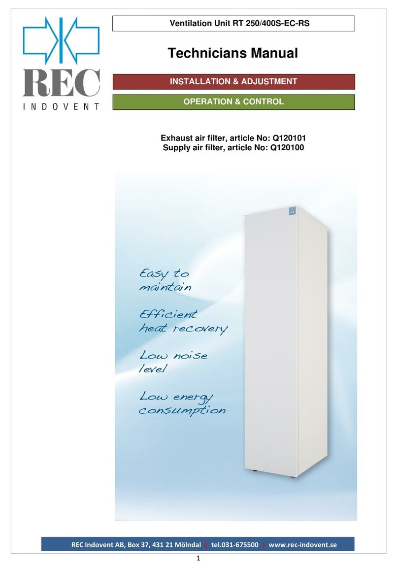
Ventilation Unit RT 250/400S-EC-RS
Checklist installation, adjustment, and start up.
☐Mounting.
The unit is mounted according to the recommendations in this manual, section “installation &
adjustment”.
☐Reheater water.
Water pipes supply and return correctly connected. Red tape = supply, blue tape = return.
In addition, in the case of an external battery, check that the reheater is correctly connected to the
supply air duct so that the air flow going in the right direction.
Valve and actuator installed on the return line. (Electrically, it is normally connected from the factory).
☐Freeze protection sensor.
Freeze protection sensor is applied to the return line, insulated and electrically connected.
(In the case of internal water coil, this is pre-assembled from the factory).
☐Cooling coli.
Refrigerant supply and return correctly connected. Red tape = supply, blue tape = return. In addition,
check that the cooling battery is correctly connected to the supply air duct so that the air flow goes in
the right direction. Valve and actuator installed on the return line. (Electrically, it is normally connected
from the factory).
☐Duct-connection.
The units 4 duct connectors are correctly connected to the respective duct.
The out-air connector to the duct coming from outside the house.
The supply air connector to the duct that goes to living-room, bedroom and so on.
The extract air connector to the duct from kitchen, bathroom and so on.
The exhaust air connector to the duct that goes out of the house.
☐Sensor connection.
The out-air sensor is placed in the out-air duct.
The supply air sensor is placed in the supply air duct and at least 0,6m after reheater and possibly
cooling coil.
☐Condensate drain.
Condensate drain connected according to recommendations in this manual, section "Installation &
Adjustment".
☐Possibly additional accessories.
☐Outdoor air damper (ULS): Check function open / close
☐Fireplace switch: Check function
☐Remote panel easy (TG-R4): Check function
☐Remote panel with display: Check function
☐Remote panel 3-way: Check function
☐Airflows adjusted.
When all airflows are correctly adjusted, note the fan's normal %-rates here in the manual.
Supply air fan normal: % Extract air fan normal: %
_______________ _______________
☐Program function.
It is appreciated if the function of the digital inputs is noted below.
DI1: ☐Not active, ☐Min flow, ☐Boost flow, ☐Max flow, ☐Kitchen, ☐ECO, ☐Stove, ☐AH On/Off, ☐Normal.
DI2: ☐Not active, ☐Min flow, ☐Boost flow, ☐Max flow, ☐Kitchen, ☐ECO, ☐Stove, ☐AH On/Off, ☐Normal.
DI3: ☐Not active, ☐Min flow, ☐Boost flow, ☐Max flow, ☐Kitchen, ☐ECO, ☐Stove, ☐AH On/Off, ☐Normal.
DI6: ☐Not active, ☐Min flow, ☐Boost flow, ☐Max flow, ☐Kitchen, ☐ECO, ☐Stove, ☐AH On/Off, ☐Normal.
☐Save settings.
When everything is ready, please save the settings by activating the "Save settings" function.
(Then all settings can be revoked in the event of future service if something should go wrong).
See the Technical Manual for more info!
Date: ________________________ Name: __________________________________________


