INSTALLATION & ADJUSTMENT
Ventilation unit Temovex Blue 2 / 4
REC Indovent AB, Box 37, 431 21 Mölndal | phone: 031-675500 | www.rec-indovent.se
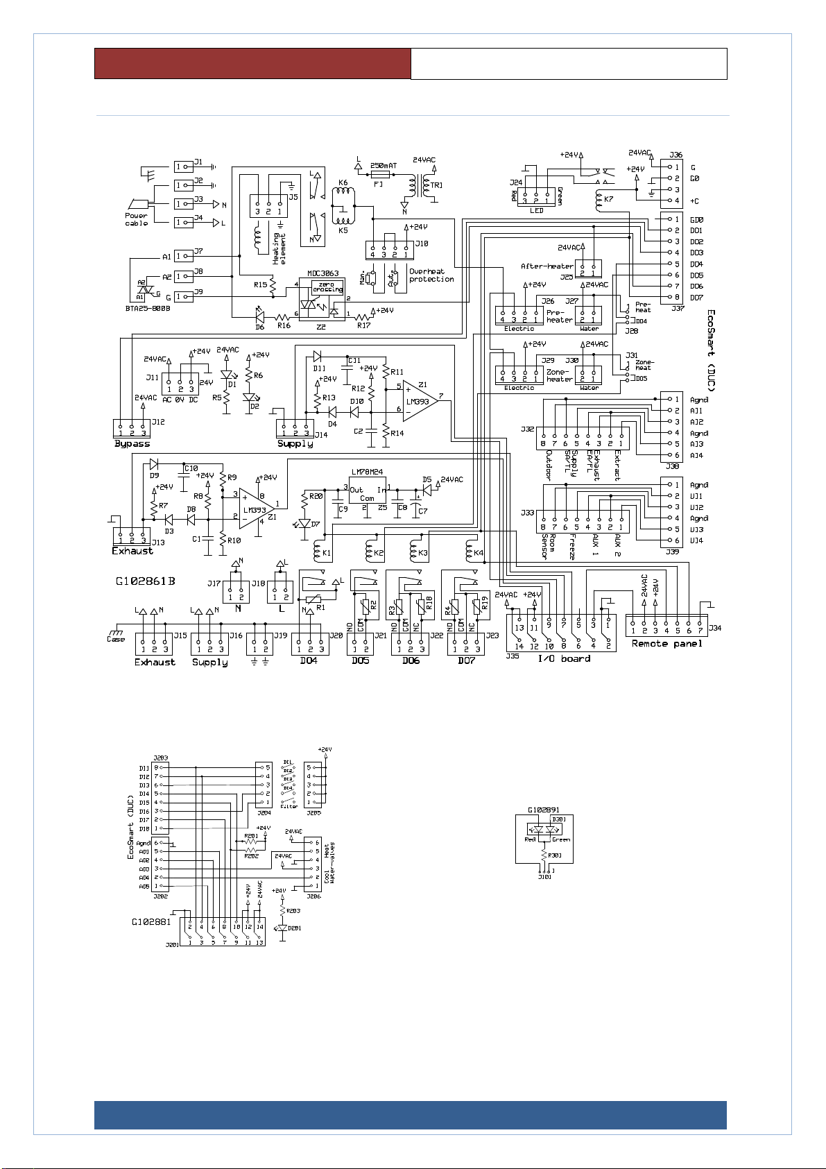
Terminal Description
General information
Most connections are made on the circuit boards. There are
also texts that indicate where different things should be
connected. All terminals have a J xxx no. indicated and a small
triangle at pin 1.
When stated below, for example, J26/1,2 is meant to be
connected to terminal J26 on pins 1 and 2.
In some cases, there are also signal markings on the card.
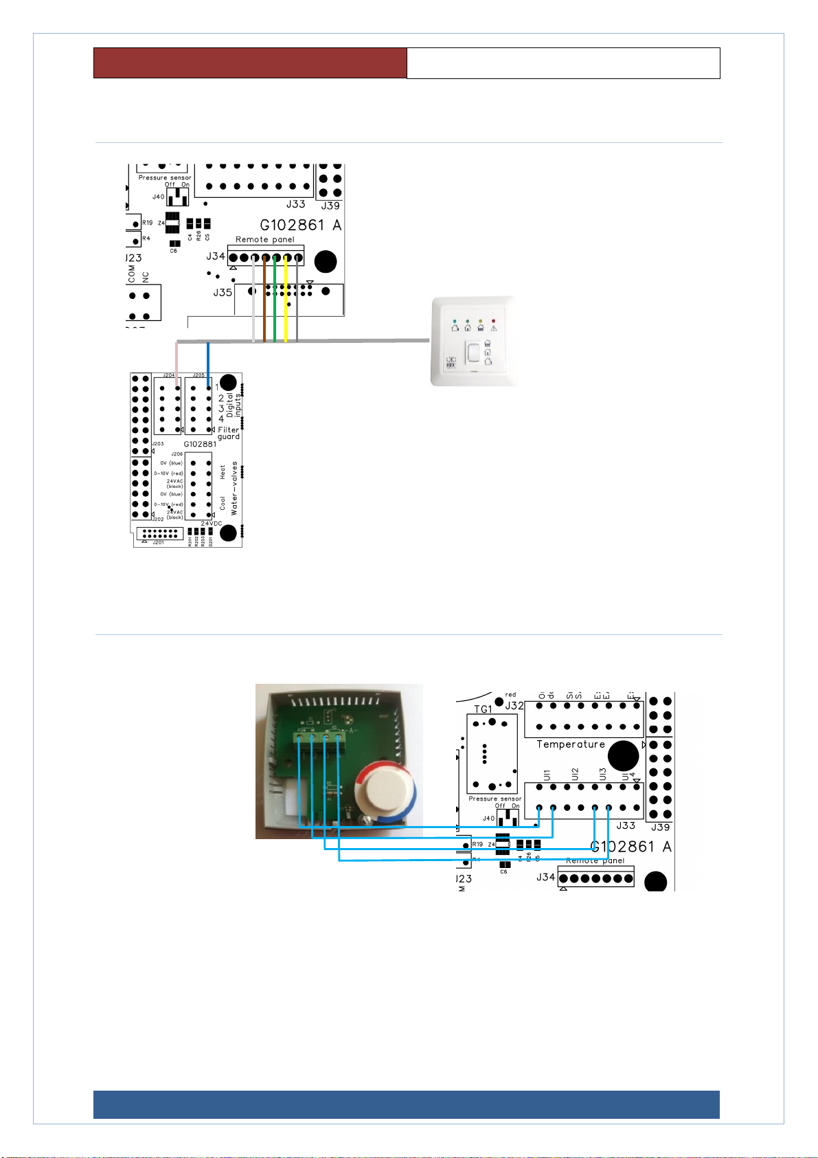
Room sensor (Terminal J33/7.8)
If room sensor is to be used, keep in mind that room control
must be selected in the configuration of the system.
External cooling (Terminal J206/1,2,3)
The system also has ability to handle an external water-cooling
battery, e.g., natural cooling from boreholes.
The cooling battery is controlled via an external valve (0 - 10 V).
After heater water (Terminal J206/4,5,6)
The water heater is controlled via an external control valve
0-10V (Possibly is the cable already connected at delivery).
Temperature sensor (Terminal J32)
Temperature sensors (PT1000) for outdoor air, supply air,
extract air and exhaust air are already connected at delivery.
Freeze protection (Terminal J33/5.6)
To prevent freezing of the water battery in the case of water
heating, a freeze protection sensor (temperature sensor) is
placed on the return line from the water battery.
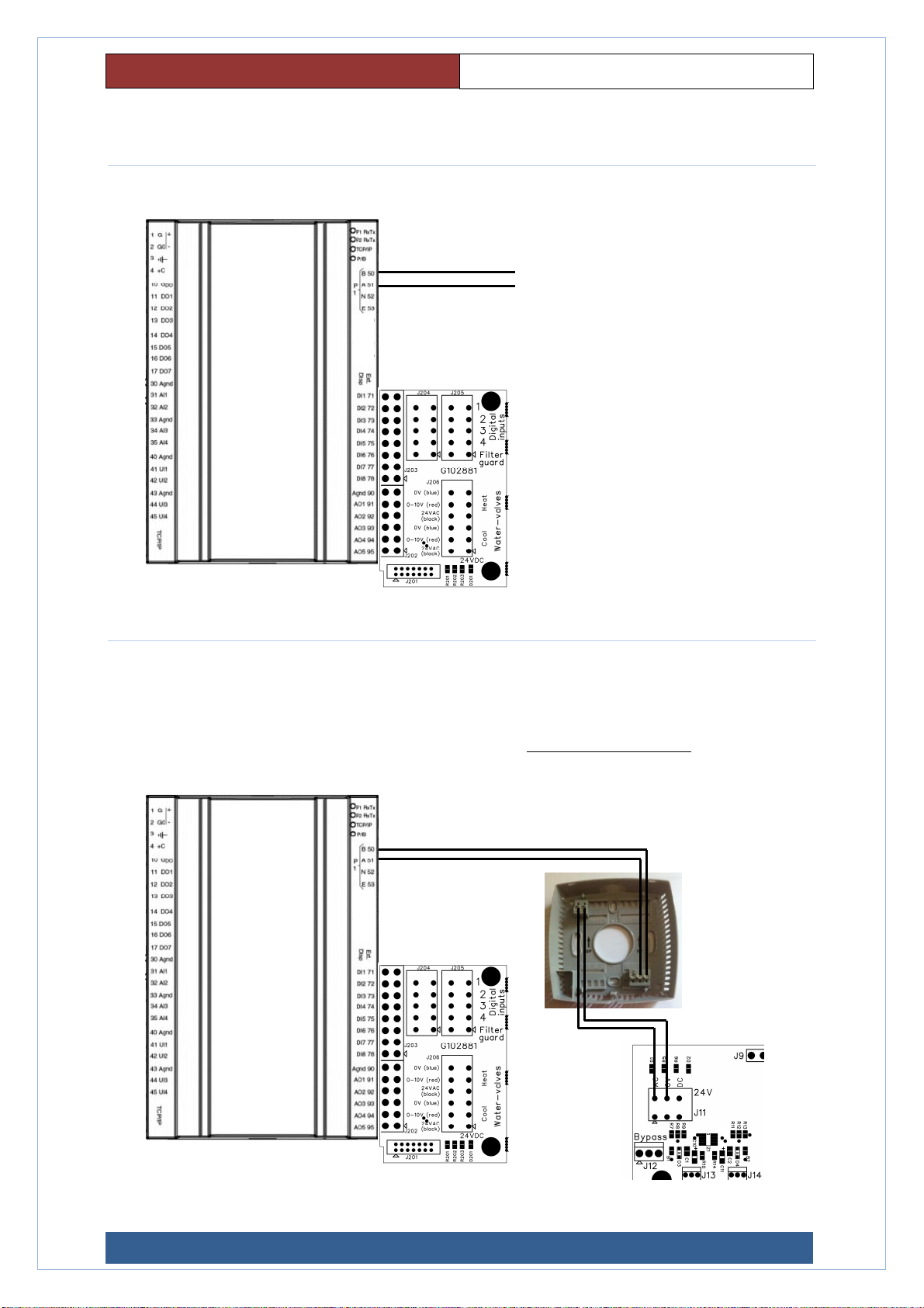
Remote panel (Terminal J34)
Terminal for connecting a remote control (optional) with among
other things alarm indication and a switch for ECO mode.
NOTE! When using ECO Remote, DO6 must be configured for
Normal flow, DO7 for Sum alarms and DI2 to ECO.
Fans power supply (Terminal J15 and J16)
Connection terminals for power supply to the fans. These are
already connected at delivery.
Fans control signals (Terminal J13 and J14)
Connection terminals for control signals to the fans. These are
already connected at delivery.
Bypass (J12)
Connection terminal for the bypass damper. The cable is
already connected at delivery.
Electric heater power supply (J5)
Pin 1 PE, pin 2 neutral, pin 3 phase.
Electric heater overheat protection (Terminal J10)
Electric heater triac connection (J7, J8, J9)
Electric preheater control signals (Terminal J26)
In case of electric preheating, J28 should be in preheat position.
Otherwise "DO4". (In case of electric preheating, DO4 cannot be
used).
Electric zone heater control signals (Terminal J29)
In the case of electric zone heating, J31 must be in the "zone
heat" position. Otherwise "DO5".
After heater water (wax actuator) (Terminal J25)
Preheater water (wax actuator) (Terminal J27)
Zone heater water (wax actuator) (Terminal J30)
DI1, DI2, DI3 and DI4 (Terminal J204 and J205)
There is, as an option, the possibility to connect four external
switches which at closing change the fan speeds according to
the choices made during configuration. Appropriate flows are
preset but can be changed by a qualified installer via the control
panel.
For available choices see section "Operation & Control".
Option terminal filter guard (J204.1 and J205.1)
Relay output DO4 (Terminal J20)
This output has a closing function for 230VAC and is suitably
used for outdoor air dampers, KAVK or other 230VAC
consumers. For configuration see section "Operation &
Control".
Relay output DO5 (Terminal J21)
This output has a free closing function that can be used for
either 230VAC or 24V. For configuration see section " Operation
& Operating".
Relay output DO6 (Terminal J22)
This output has a free closing function that can be used for
either 230VAC or 24V. For configuration see section "Operation
& Control".
Relay output DO7 (Terminal J23)
This output has a voltage independent NO-NC function that is
configured as a sum alarm at delivery.
It is quite possible to use the output for other functions, but
then the status LED above the door does not work, since it is
connected to the same output, but with a separate relay.
If the output is to be used for anything other than a sum alarm,
we recommend disconnect the LED so as not to get misleading
information. This is easily done by removing the cable to the
LED.
For configuration see section "Operation & Control".
LED output status LED. (Plint24)
Mains voltage (Terminal J2, J3, J4)
230VAC, 50Hz
Chassis (Terminal J1)
Ground connection to chassis
Socket low voltage (Terminal J11.)
Power outlet (Terminal J17, J18, J19)