manuals.online logo
Brands
  1. Home
  2. •
  3. Brands
  4. •
  5. Red Arrow
  6. •
  7. Lighting Equipment
  8. •
  9. Red Arrow ANA/30 User manual

Red Arrow ANA/30 User manual

PAGE 2 (FRONT PAGE)
Athena M/NM Exit Sign (/ST Version with Self Test)
Product Codes: ANA/30 & ANA/30/ST
Box Contents -
1 x Exit Sign c/w Blade Style Up Arrow Legend./ST Version with Self Test Functionality.
Dimensions: H: 212 x W: 313 x D: 42mm
Material: Polycarbonate
Colour
Temperature: 6500K
CRI: Ra>80
LED Lifetime: L70B50 36,000 Hrs
IP Rating: IP20
Working
Temperature: 0°C to 45°C
Guarantee: 5 Years
Safety Warning
• The installation should be carried out
by a qualied electrician in compliance
with the current edition of the IEE
Wiring Regulations.
• Prior to installation, carry out the
necessary risk assessment considering
the people who could be at risk,
the level of risk and the precautions
required to control the risk
• Ensure that the circuit supply is
isolated either by the circuit supply
fuse being removed or the applicable
circuit breaker being turned o before
installation or any maintenance.
• Check the total load on the circuit
ensuring the luminaire does not exceed
the rating of the circuit cable, fuse or
circuit breaker.
• Long-term use and voltage uctuations
can reduce the life span of the tting.
• If the tting incorporates control gear,
ensure careful sizing to avoid instances
of nuisance tripping of the protective
device used in the installation.
• Follow the provided installation
instructions, using the xings supplied
or recommended.
• Keep out of reach of children.
INSTALLATION INSTRUCTIONS
PAGE 1 (FRONT PAGE)
Specication
PAGE 1 (FRONT PAGE)
230V
IP20
5
YR
GUARANTEE
2.2
WATT LED
6500K
1. Isolate the mains supply before carrying out any installation or maintenance work.
2. Remove the front cover from the tting. Using a at blade screwdriver, turn the locking screw a quarter turn anti-clockwise until it lines up with open
padlock symbol, then remove front from base.
3. Drill out the preferred xing points and cable entry on the base for either wall or ceiling mounting. Fix the base to the wall or ceiling in the desired location,
using the xings supplied and passing the supply cable through the cable entry point. Ensure that a suitable grommet or similar is used at the cable entry
point.
Installation Instructions
23
(Self Test Version Only)
W313mm
H212mm
H161mm
D42mm
Wall
Ceiling
PAGE 2 (FRONT PAGE)
PAGE 1 (FRONT PAGE)
PAGE 1 (FRONT PAGE)
4. Connect the supply cable to the terminal block. An unswitched supply must be connected to the Live (L) and Neutral (N) terminals. Use the tted cable
strain relief clamp.
5. Plug the cable from the battery into the white 3 pin connector on the PCB. Plug the power lead from the terminal block onto the power connection on the
PCB
6. The tting can be set up for maintained or non-maintained operation. This is selected using the jumper plug on the PCB. Plug the jumper into pins 1 & 2 for
maintained operation or pins 2 & 3 for non-maintained. The jumper is set for maintained by default.
8. Restore the mains supply and check that the green LED indicator is illuminated and that the luminaire operates correctly.
9. Leave the power connected for 24 hours to fully charge the batteries and then carry out an emergency commissioning test.
10. This tting is supplied with an Up Arrow legend as standard. Down and Left/Right arrow legends are available to order separately. To replace, remove the
2-part locking pins at the bottom of the legend blade, using a small diameter tool to push out the inner pin from the back rst. The legends can then be
removed and replaced. Re-insert the 2-part locking pins after aligning the holes on the legends with those on the blade and snap together.
Self Test Version Only
ANA/30/ST features stand alone automatic self test operation.
After the power supply has been connected and the batteries have charged for 24 hours, the tting will perform the following tests automatically, which meet
and exceed legal requirements. The status during and after the tests is provided by a bi-colour LED Indicator
Initial Duration Test
This is carried out 24 hours after the tting has been connected to the power supply, provided the supply is uninterrupted and the batteries have been charging
for this period. This test lasts for the rated duration of the luminaire, 3 hours.
Function Test
This test is carried out every month for 3 minutes, checking the functionality of the emergency module, batteries and LED module.
Duration Test
This is carried out every year (every 300 to 365 days). The test lasts for the rated duration of the luminaire, 3 hours.
NOTES:
If a mains supply failure occurs during a scheduled test or in the preceding 24 hours, the test will be postponed for 3 days.
The timing function is accurate to within ± 75s per week. Timing is retained during periods of mains failure or interruption for up to 7 days.
Tests will not be performed when the mains supply is disconnected
7. Replace the front cover. Engage the tabs/slots and slide into position. Secure the cover by rotating the locking screw a quarter turn clockwise until lines up
with the closed padlock symbol.
7
10
4
(Blue) N
E
(Brown) L
Blue
Brown
5 6
Maintained
Non-Maintained
NOTE: This tting can also be installed using a suspension kit (ANA/SK), recessing kit (ANA/RK) or wall ag mount kit (ANA/WFK), all available to order separately.
Instructions for use supplied with each kit.
PAGE 4 (THREE - INSIDE DPS)
This product is guaranteed for a period of 5 years (batteries 2 years) from the date of purchase. The guarantee is invalid in the case of improper use, tampering,
removal of the Q.C. date label, installation in an improper working environment or installation not according to the current edition of the I.E.E. Wiring
Regulations (BS7671). The guarantee is also invalidated if the luminaire has been insulation tested. Should this product fail during the guarantee period it will be
replaced free of charge, subject to correct installation and return of the faulty unit. We do not accept responsibility for any installation costs associated with the
replacement of this product. Your statutory rights are not aected. We reserve the right to alter specications without prior notice.
Guarantee
• This tting will require routine cleaning if used in adverse (dust, paint, welding, oils etc) environments. Do not use solvents, aggressive detergents or
abrasives.
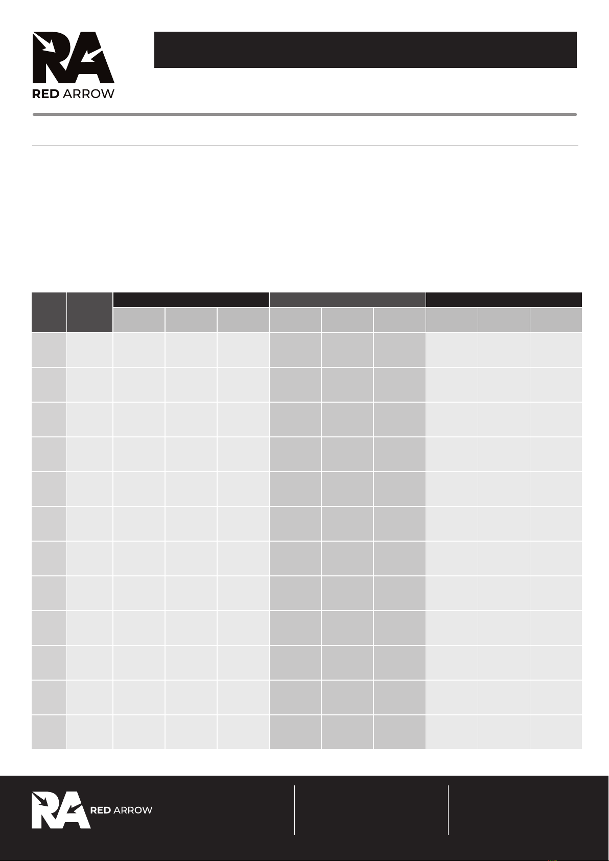
• The light source & driver in this luminaire can be quickly and easily replaced at end of life. This should be carried out by a competent person. Contact Red
Arrow for details of replacements.
Maintenance
• When this tting comes to the end of it’s life or you choose to replace it, please do not dispose of it with your normal waste. Please recycle where the
facilities exist, check with your local authority for suitable options.
INS_EMERGENCY_0021_ANA_V1
PAGE 3 (TWO - INSIDE DPS)
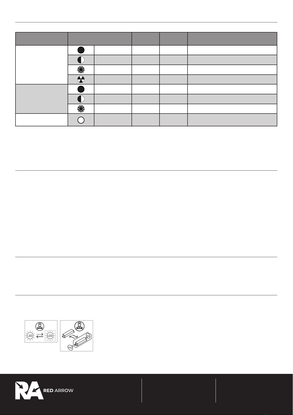
System Status Indication
The system status, including testing and any faults is provided by a bi-colour LED indicator on the tting. Status is provided as follows:
LED Colour Status Flash Rate
On Time
Flash Rate
O Time
Details
Green Permanent On - - Normal operation - Battery is charging
Slow Flash 1s 1s 3 hr duration test in progress
Fast Flash 0.2s 0.2s 3 min function test in progress
Flash 3 Times only 0.5s 0.5s Self test timer reset
Red Permanent On - - Battery charge failure
Slow Flash 1s 1s LED module failure
Fast Flash 0.2s 0.2s Battery duration failure
O O - - System in emergency mode. Mains disconnected
from battery, or mains failure
Test Button
The tting has a test button, which can be used to perform the following functions:
Press for < 2s – Simulate emergency mode
Press for 3-5s – Manually start a duration test. Abort test by pressing the button for 1-2s
Press for 5-8s – Manually start a 60s function test. Abort test by pressing the button for 1-2s
Press for > 10s – Timer reset
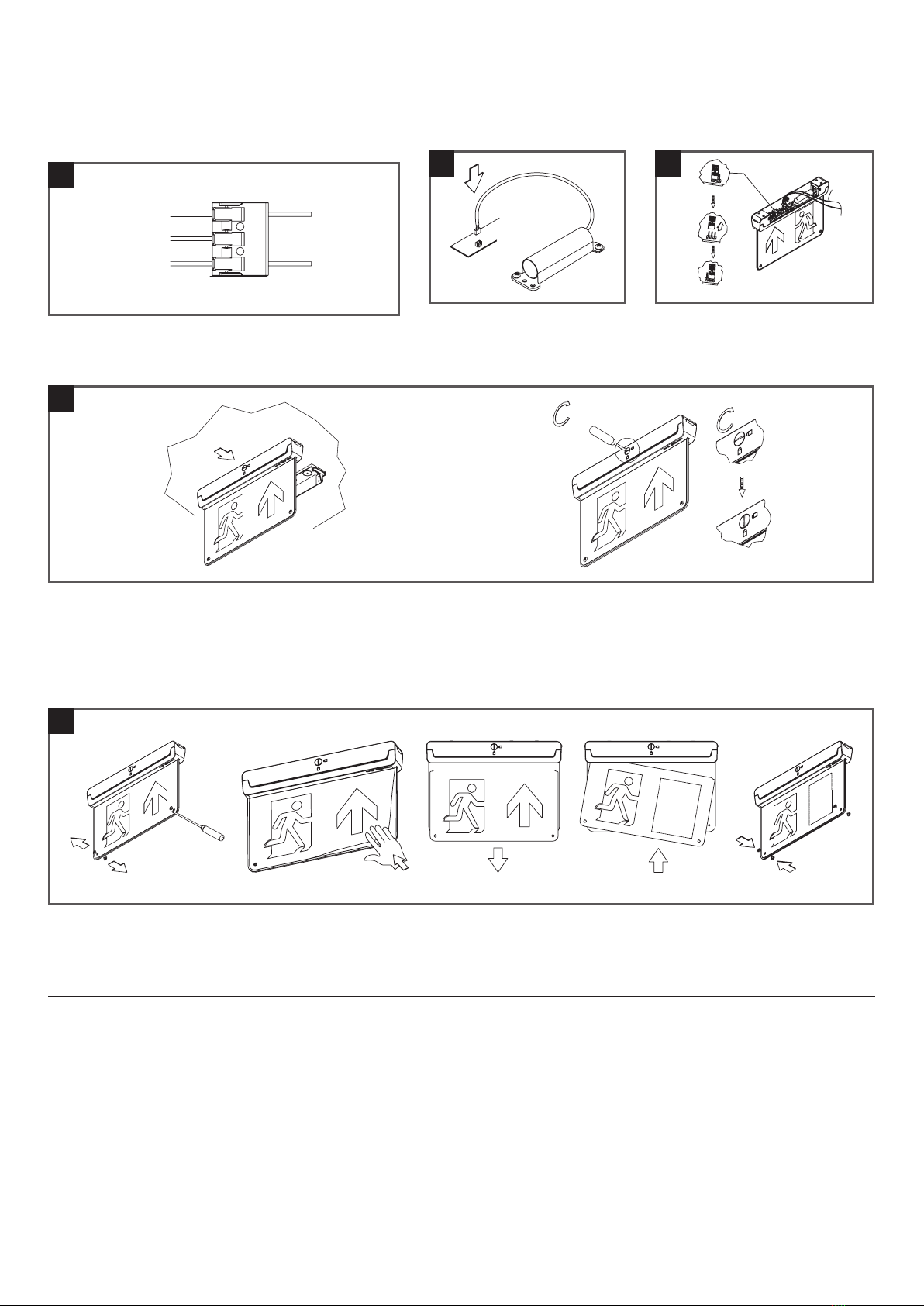
Battery Replacement
1. Isolate the mains supply and remove the front cover.
2. Unplug the battery lead from the circuit board.
3. Write the current date on the new battery pack.
4. Fit the new battery pack.
5. Plug the battery back into the circuit board.
6. Replace the front cover, restore the power and allow to charge for 24 hours. Then carry out a full duration test.
7. Self Test Version Only – After restoring the power press the test button for >10s to reset the timer and allow to charge for 24 hours.
8. Self Test Version Only – The tting will carry out an automatic duration test after 24 hours. Check the indicator status after the test for normal operation
T: 0800 195 0006
sales@redarrowelectrical.co.uk
Red Arrow Electrical Ltd
Cortonwood Drive, Brampton,
Barnsley, S73 0UF redarrowelectrical.co.uk
PAGE 4 (THREE - INSIDE DPS)
PAGE 3 (TWO - INSIDE DPS)
INS/EMERGENCY_TESTING_SHEET/V2
Emergency Testing Sheet
INSTALLATION INSTRUCTIONS
Month Test
Year 1 Year 2 Year 3
Signed Result /
Action Date Signed Result /
Action Date
1Functional
2Functional
3Functional
4Functional
5Functional
6Functional
7Functional
8Functional
9Functional
10 Functional
11 Functional
12 Full
Duration
Testing (Emergency Versions)
The emergency lighting must be tested and inspected regularly in accordance with local codes of practice.
NOTE: For safety reasons tests should be carried out preceeding time of low risk, to allow for battery recharge.
The minimum recommended test schedule is as follows:
Commisioning - After installation, allow 24 hours to ensure full battery charge, and then interrupt the supply; check after 3 hours that the light is still illuminated.
1. Daily - Check that the charge indicator LED is working.
2. Monthly - Interrupt the power supply for a period sucient to ensure each light is illuminated. At the end of the test, restore the supply and check the
indicator is illuminated.
3. Annually - Interrupt the supply as in 2, but for the full rated duration. Ensure the light is illuminated at the end of the rated duration. Restore the supply and
check the indicator is illuminated.
4. Record the date and result of each test, attending to any maintenance required in the event of a test failure.
Luminaire Location ................................................................. Date Installed ......................................
Date Commisioned .................................................................
T: 0800 195 0006
sales@redarrowelectrical.co.uk
Red Arrow Electrical Ltd
Cortonwood Drive, Brampton,
Barnsley, S73 0UF redarrowelectrical.co.uk

This manual suits for next models

1

Other Red Arrow Lighting Equipment manuals

Red Arrow Jupiter JUPS30-40 User manual

Red Arrow

Red Arrow Jupiter JUPS30-40 User manual

Red Arrow LF13LEDPIR User manual

Red Arrow

Red Arrow LF13LEDPIR User manual

Red Arrow POLO 15W LED User manual

Red Arrow

Red Arrow POLO 15W LED User manual

Red Arrow POL14LEDEMSCF User manual

Red Arrow

Red Arrow POL14LEDEMSCF User manual

Red Arrow LF502A User manual

Red Arrow

Red Arrow LF502A User manual

Red Arrow VAN/3 User manual

Red Arrow

Red Arrow VAN/3 User manual

Popular Lighting Equipment manuals by other brands

fivep lite MATRIX 1 manual

fivep lite

fivep lite MATRIX 1 manual

Laserworld Club Series manual

Laserworld

Laserworld Club Series manual

Rebel HANG Assembly and operating instructions

Rebel

Rebel HANG Assembly and operating instructions

HEISSNER L124-T Instructions for use

HEISSNER

HEISSNER L124-T Instructions for use

Larson Electronics EPL-HB-150LED-RT instruction manual

Larson Electronics

Larson Electronics EPL-HB-150LED-RT instruction manual

Lightolier 4190 Instructions for installation

Lightolier

Lightolier 4190 Instructions for installation

Beamz professional BAC306 ProPar 12x12W instruction manual

Beamz professional

Beamz professional BAC306 ProPar 12x12W instruction manual

SGM P-5 Wash Light user manual

SGM

SGM P-5 Wash Light user manual

LIVARNO 3007-046L Operation and safety notes

LIVARNO

LIVARNO 3007-046L Operation and safety notes

FROG Leap Twin manual

FROG Leap

FROG Leap Twin manual

FOSCARINI Dolmen terra manual

FOSCARINI

FOSCARINI Dolmen terra manual

Lithonia Lighting ELU 4 installation instructions

Lithonia Lighting

Lithonia Lighting ELU 4 installation instructions

Abriblue OPEN Classic installation instructions

Abriblue

Abriblue OPEN Classic installation instructions

Home Accents Holiday TY477-1611-0 Use and care guide

Home Accents Holiday

Home Accents Holiday TY477-1611-0 Use and care guide

Saxby Lighting Aqualine 24V Instruction leaflet

Saxby Lighting

Saxby Lighting Aqualine 24V Instruction leaflet

Photoflex MultiDome Series instructions

Photoflex

Photoflex MultiDome Series instructions

IKEA BRUMMIG manual

IKEA

IKEA BRUMMIG manual

Eaton Lumark Axcent installation instructions

Eaton

Eaton Lumark Axcent installation instructions

manuals.online logo
manuals.online logoBrands
  • About & Mission
  • Contact us
  • Privacy Policy
  • Terms and Conditions

Copyright 2025 Manuals.Online. All Rights Reserved.