Berker 9450 01 00 Service manual
Other Berker Controllers manuals
Berker
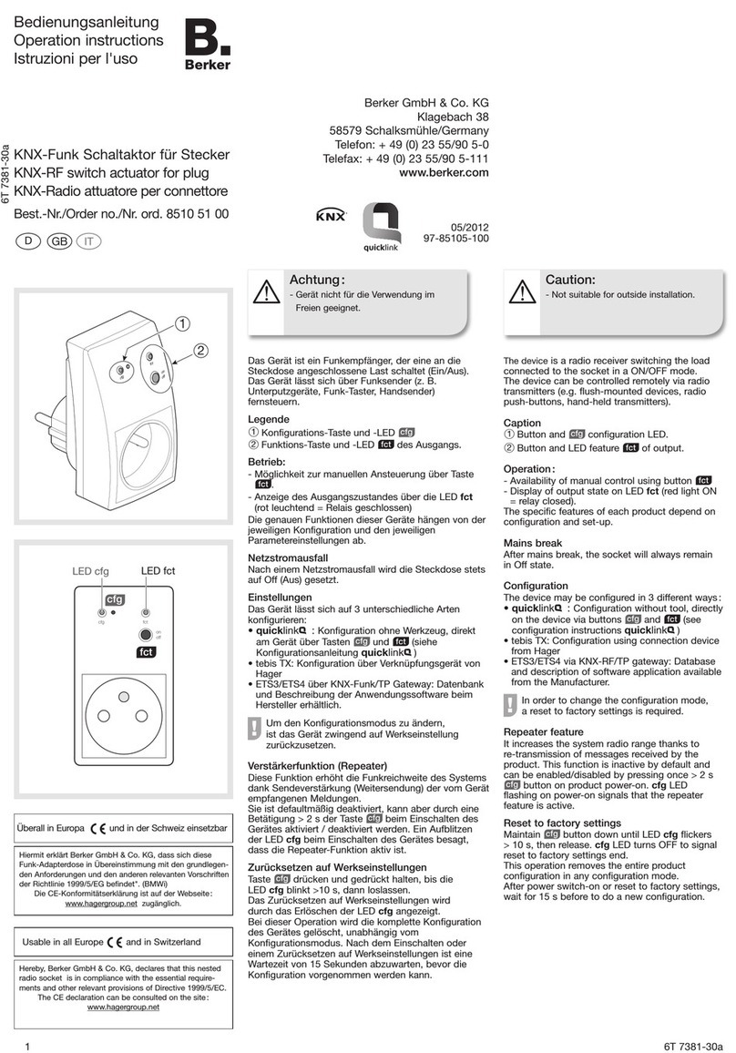
Berker 8510 51 00 User manual

Berker
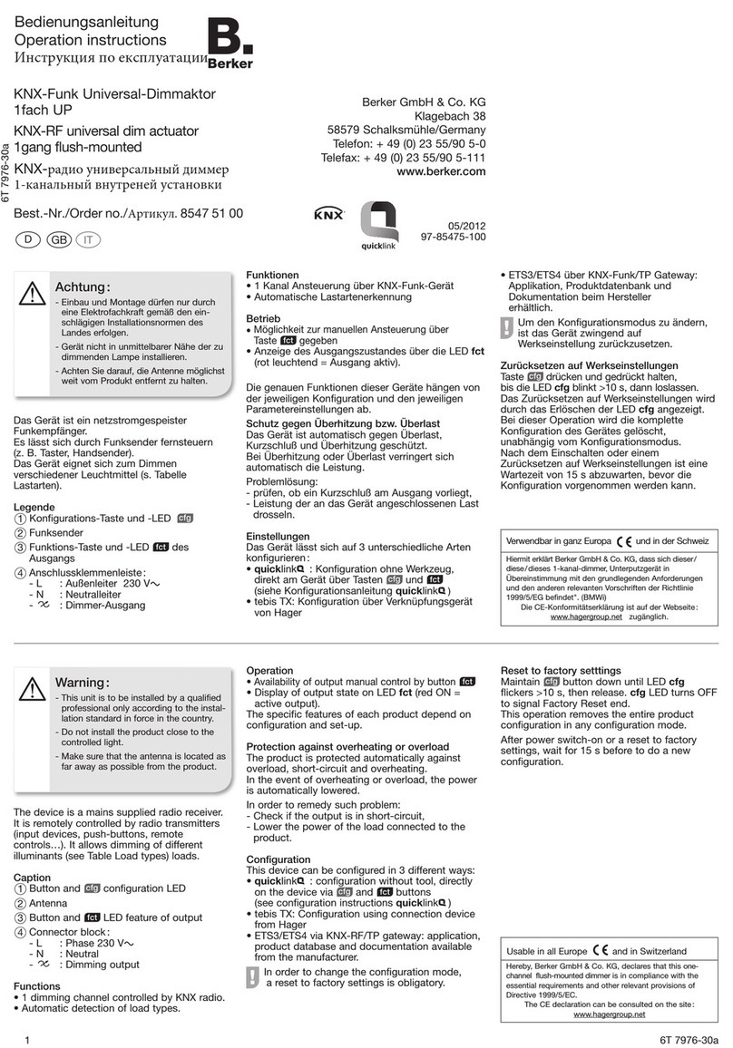
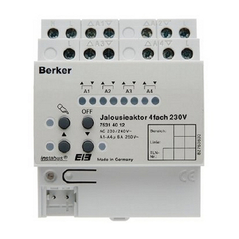
Berker KNX-RF 8547 51 00 User manual
Berker
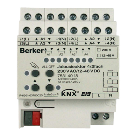
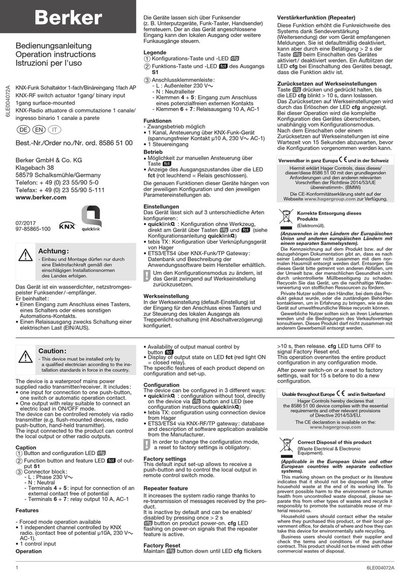
Berker 7531 40 13 User manual
Berker
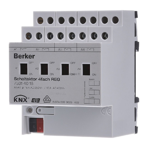
Berker 85865100 User manual
Berker
Berker 7531 40 15 User manual
Berker
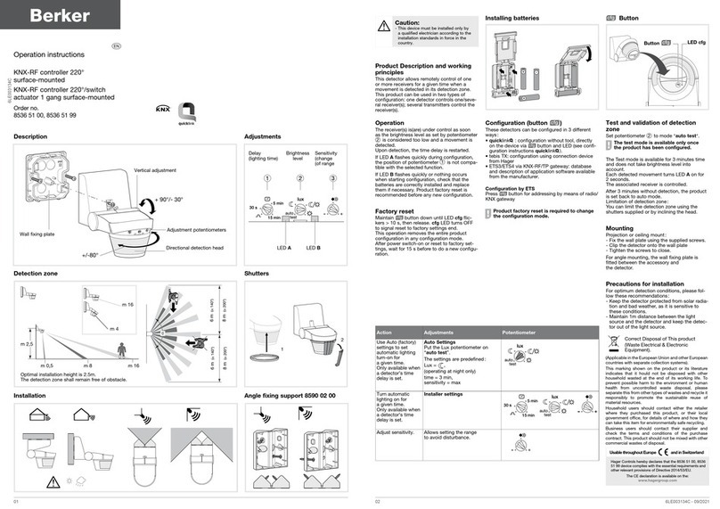
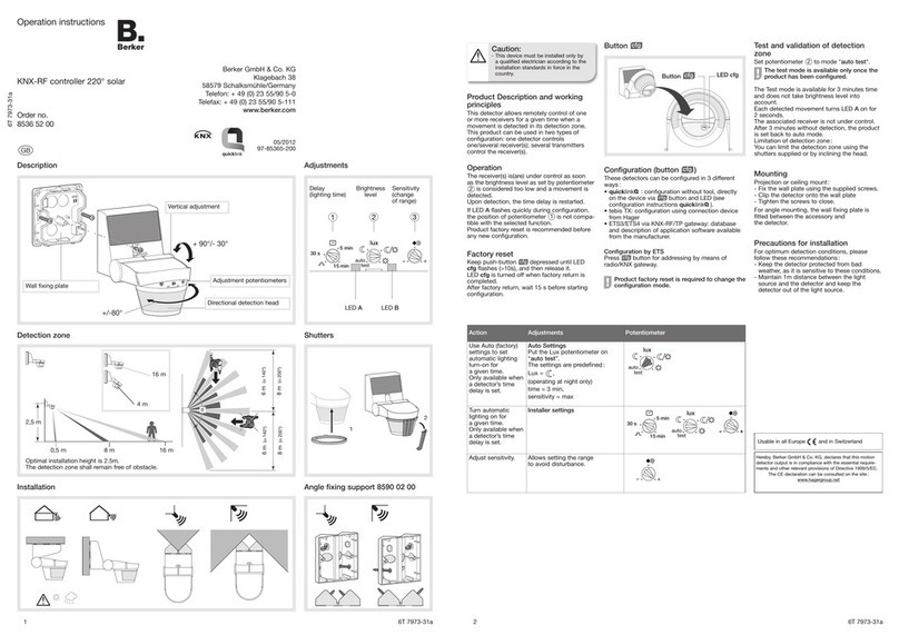
Berker 8536 52 00 User manual

Berker
Berker 9450 0200 User manual
Berker
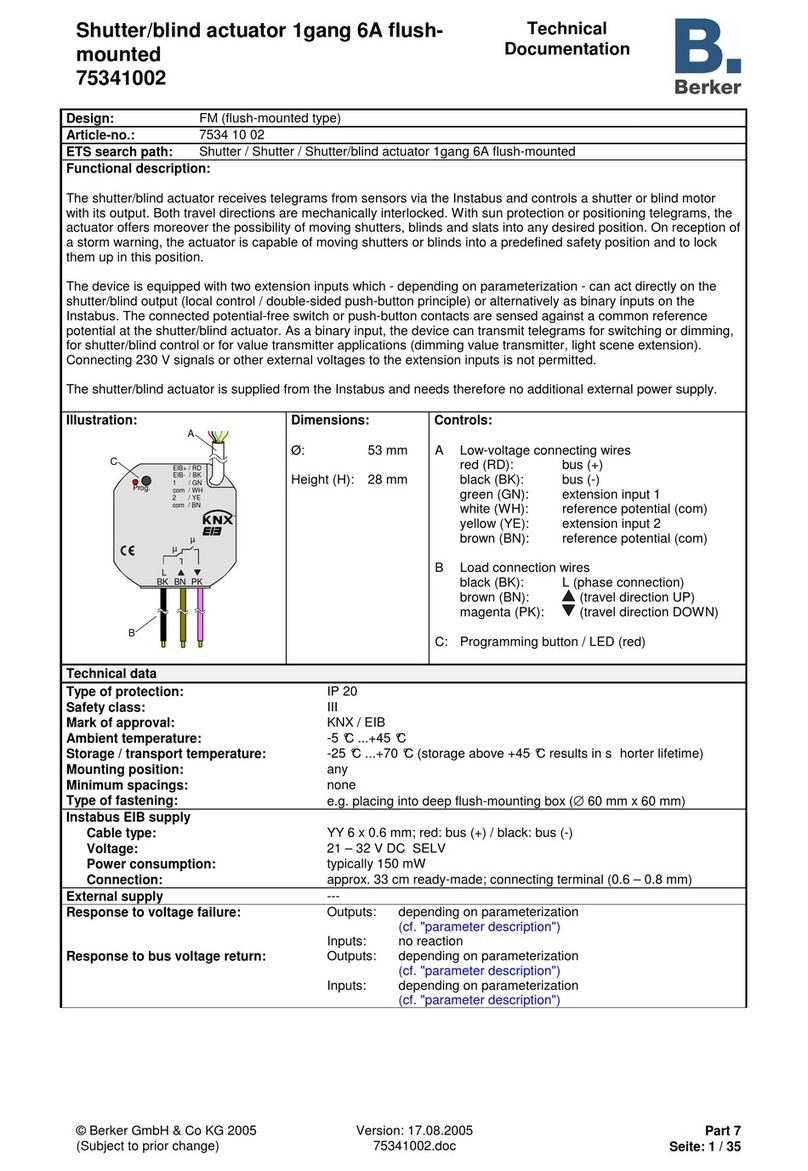
Berker 75341002 Guide

Berker
Berker 8526 51 00 User manual
Berker
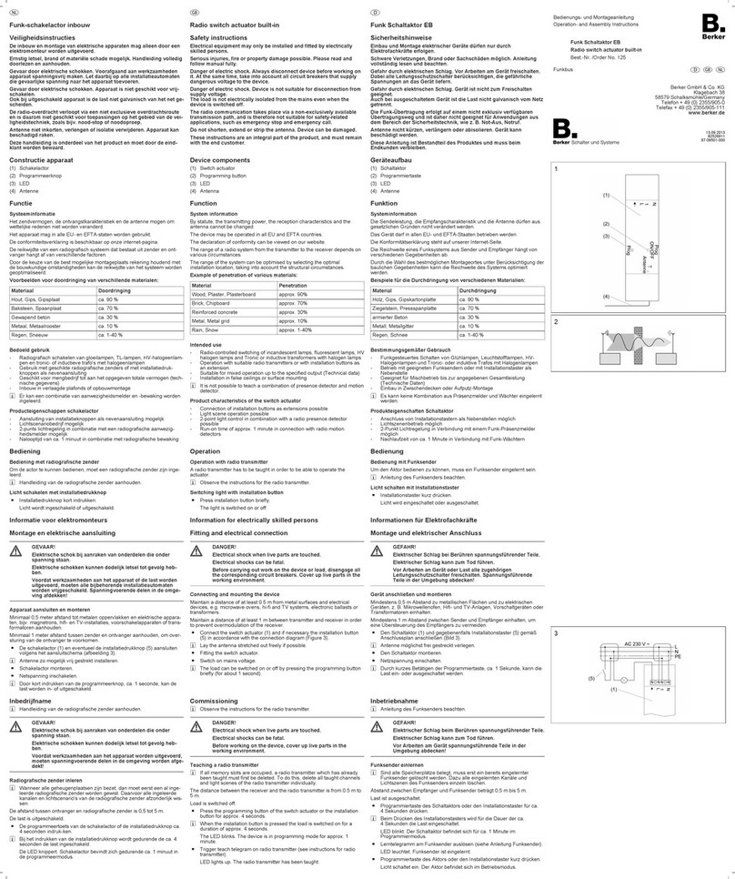
Berker 125 Service manual
Berker
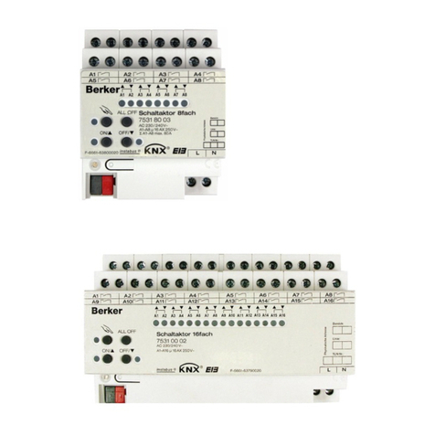
Berker 7531 80 03 User manual
Berker
Berker 7534 10 11 User manual
Berker
Berker KNX-RF User manual

Berker
Berker 7531 31 07 Product guide
Berker
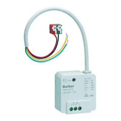
Berker 7534 10 12 User manual
Berker
Berker 8526 51 00 User manual
Berker
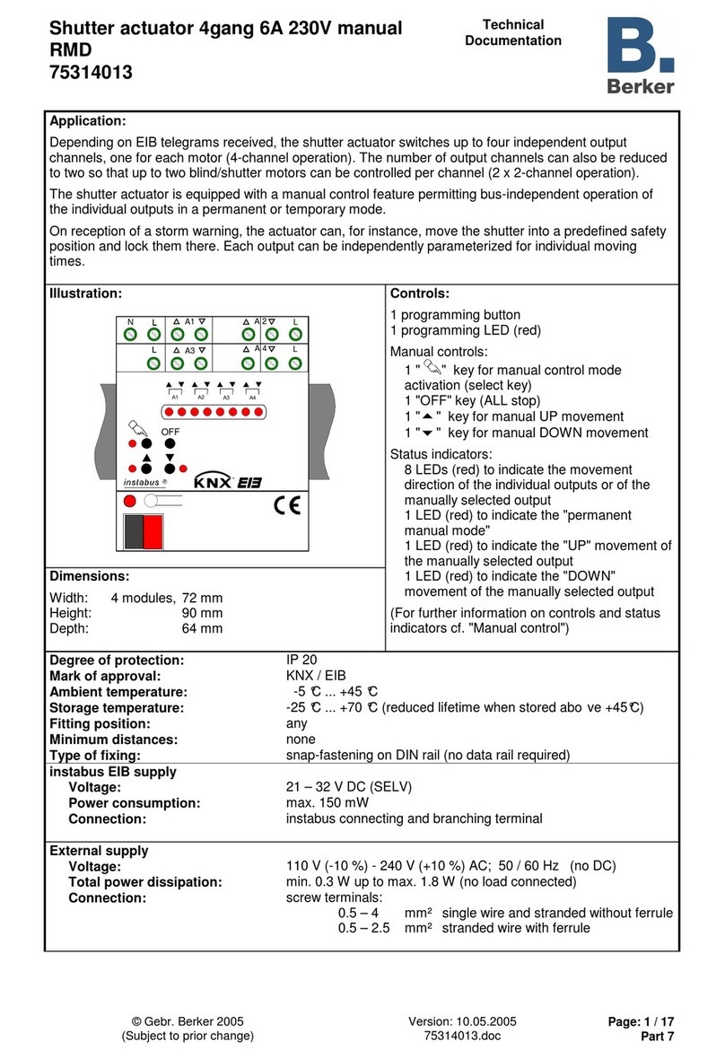
Berker RMD 75314013 Guide

Berker
Berker RMD Service manual
Berker
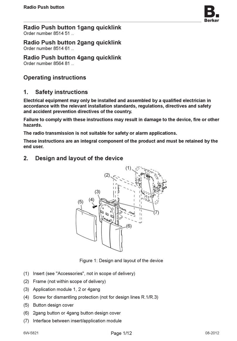
Berker Radio Push button 1gang quicklink User manual

Berker
Berker 8536 52 00 User manual
Popular Controllers manuals by other brands
SOMFY
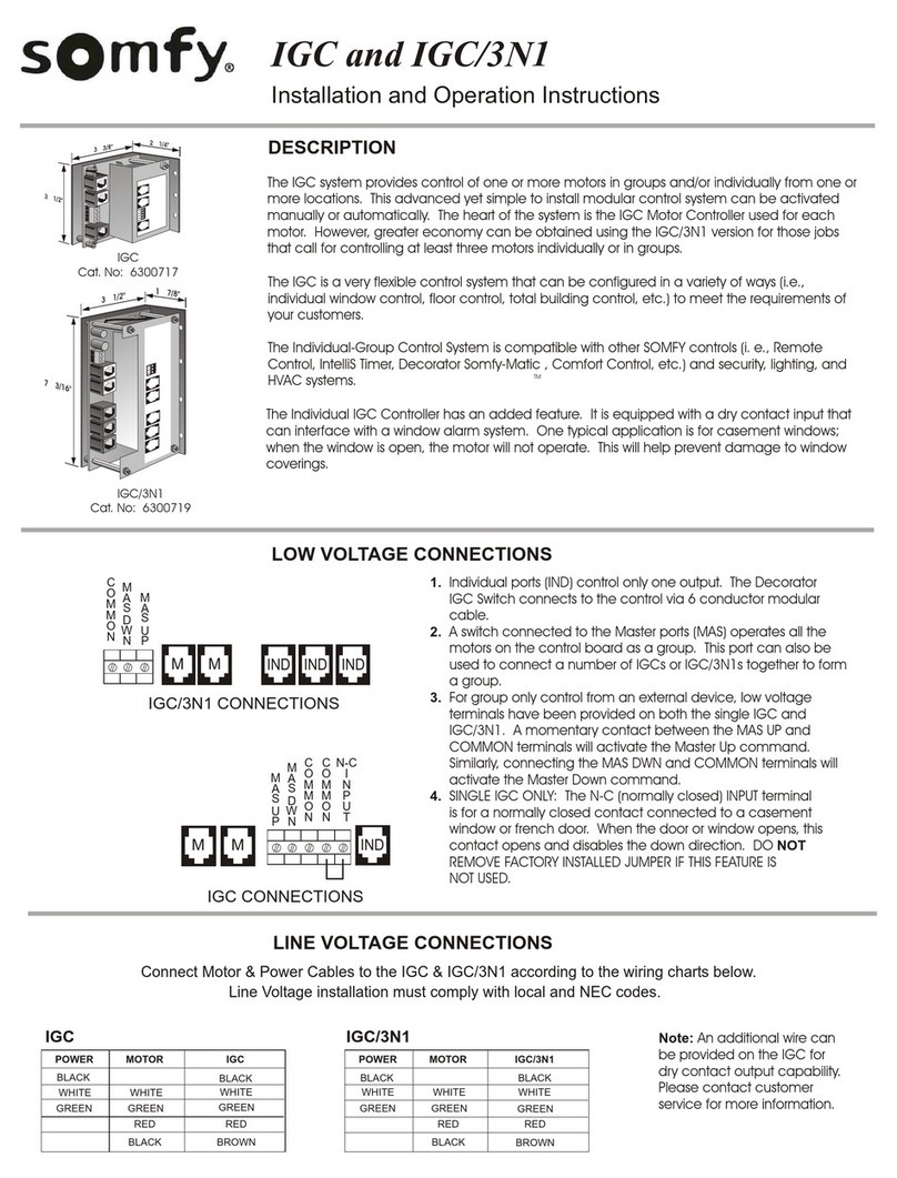
SOMFY IGC Installation and operation instructions

Xytronic
Xytronic ContrilByWeb DirekTronik X11S user manual
Silicon Laboratories
Silicon Laboratories SiM3L1xx user guide
QUANT
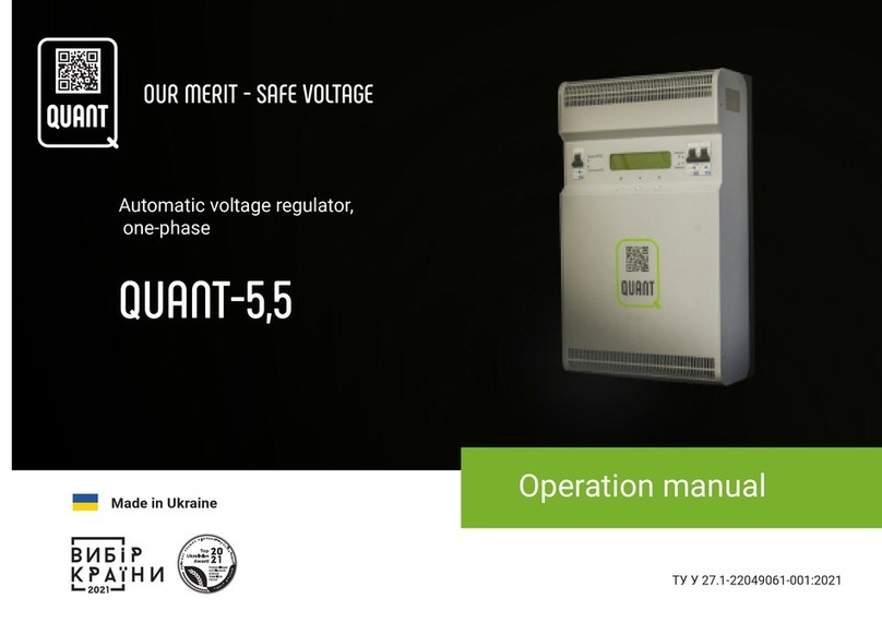
QUANT QUANT-5,5 Operation manual
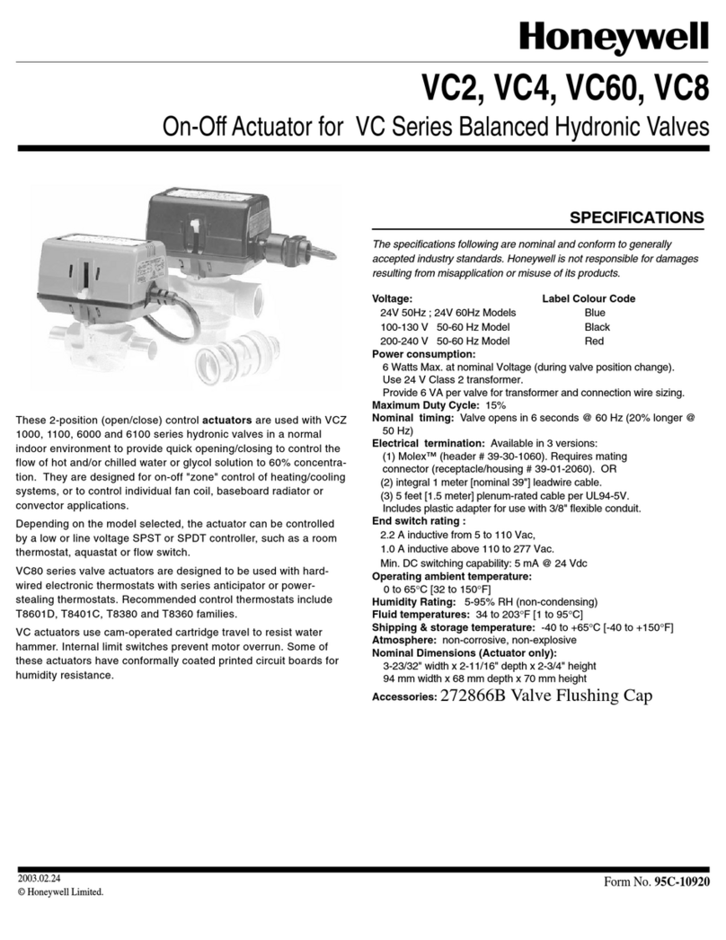
Honeywell
Honeywell VC2 Series, VC4 Series, VC60 Series,... quick start guide
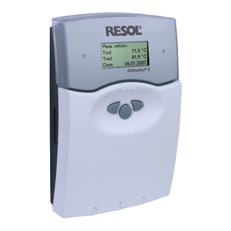
Resol
Resol DeltaSol E manual
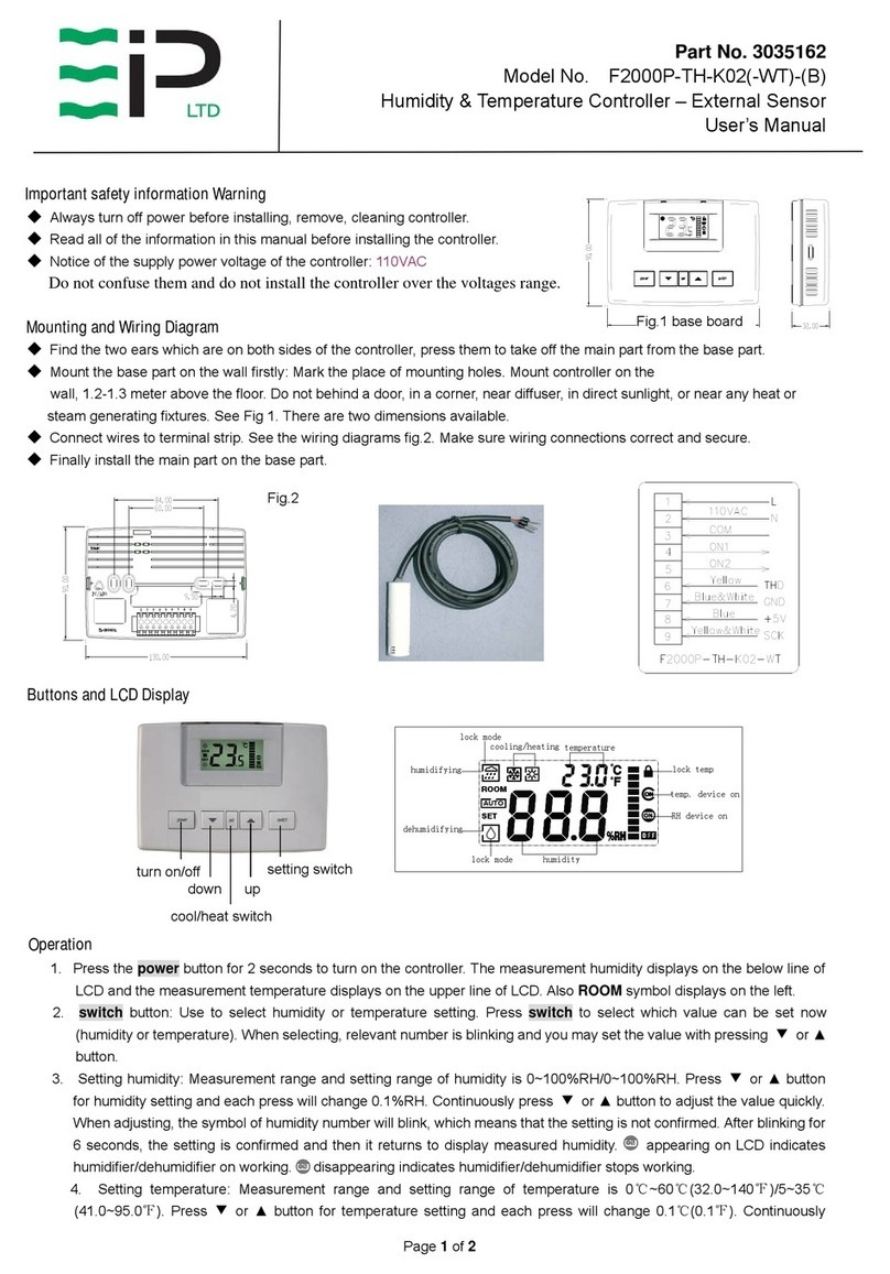
EIP
EIP F2000P-TH-K02-WT user manual
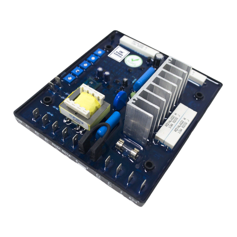
PEGASUS TECHNOLOGY
PEGASUS TECHNOLOGY GRT7-TH4 E Installation and operation manual
X-keys
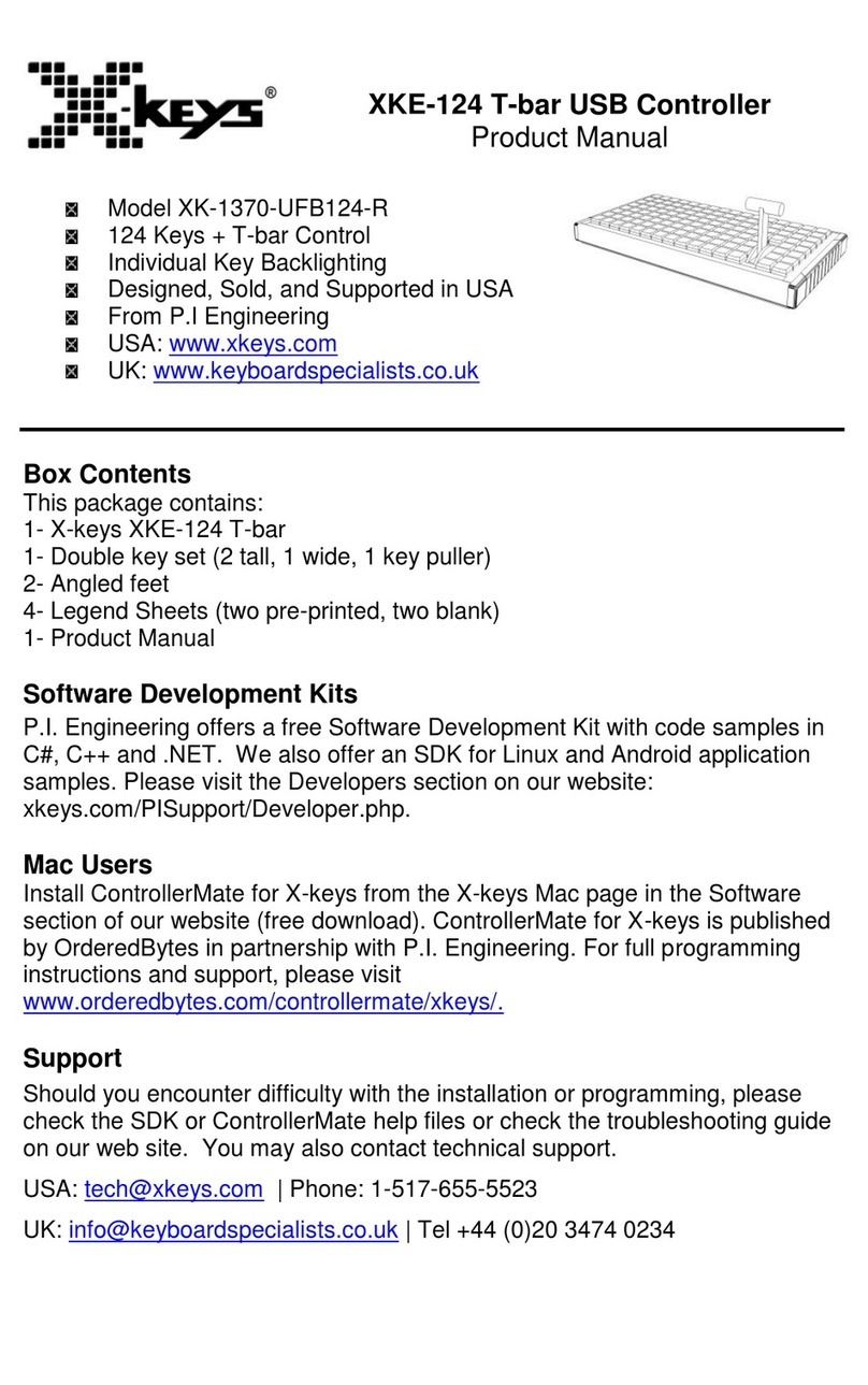
X-keys XKE-124 product manual

cashco
cashco P7 Installation, operation & maintenance manual
Endress+Hauser
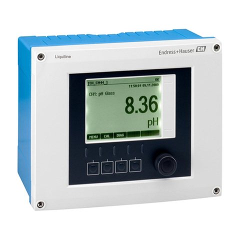
Endress+Hauser Liquiline CM442 operating instructions
ProMinent
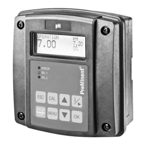
ProMinent DULCOMETER Assembly and operating instructions
RESEARCH CONCEPTS
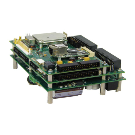
RESEARCH CONCEPTS RC4000 Protocol

Triton Blue
Triton Blue TR C 1224 user manual

DriSteem
DriSteem D77 Installation, operation and maintenance manual
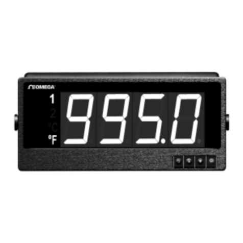
Omega
Omega ILD44-UTP quick start
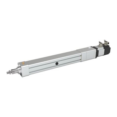
Servomech
Servomech SA Instructions for installation, use and maintenance manual
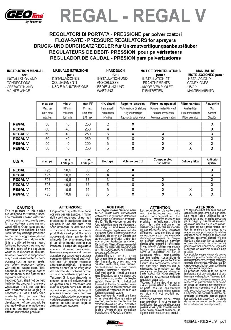
Tecomec
Tecomec GEOline REGAL Series instruction manual


