manuals.online logo
Brands
  1. Home
  2. •
  3. Brands
  4. •
  5. red lion
  6. •
  7. Measuring Instrument
  8. •
  9. red lion DITAK 6 User manual

red lion DITAK 6 User manual

!ADJUSTABLE TIMEBASE FROM 4 MSEC TO 32 SEC
!SELECTABLE DECIMAL POINTS
!REPLACEABLE LITHIUM BATTERY PROVIDES UP TO 5 YEARS
OF CONTINUOUS OPERATION (Battery included)
!RUGGED, SEALED FRONT PANEL CONSTRUCTION (NEMA
4/IP65)
!ACCEPTS MAGNETIC OR LOGIC TYPE INPUTS
!WIDE TEMPERATURE RANGE [ -30° to +75°C]
DESCRIPTION
The DT6 is a self-powered tachometer which features the ability to select the
desired Timebase by simply setting the appropriate DIP switches on the rear of
the unit. It also features a 4-digit LCD display with selectable decimal points.
The DT6 is powered by an internal 3.0 V lithium battery which is field
replaceable.
Like other Micro-Line products, the DT6 combines the use of a custom
CMOS LSI counter chip and custom Timebase gate array. These chips are
mounted on a gold-plated substrate and electrically connected by ultrasonic
wirebonding. Internal electrical interface connections use elastomeric contacts
to provide a gas-tight, corrosion resistant connection. Using the latest in Micro-
Electronic assembly and manufacturing techniques provides units with
reliability and dependability required for industrial service. The DT6 has a
metal die-cast front bezel that is sealed and meets NEMA 4 specifications for
wash-down and/or dusty environments, when properly installed.
SPECIFICATIONS
1. DISPLAY: 4-Digit LCD, 0.35" (9mm) high digits.
2. POWER SOURCE: Internal 3.0 V lithium battery to provide up to 5 years
of continuous service. For replacement procedure, refer to the illustration.
The DT6 also receives power from a logic or magnetic input signal with a
min. peak voltage of 4.0 V, which will serve to extend the battery life.
3. SIGNAL INPUT: * 0-10 KHz from a magnetic or bi-polar output (with a
50% duty cycle). Min. input sensitivity is 0.7 V. Input signal voltages over
6 V peak require an external series resistor to limit the input current to 10 mA
max.
4. TIMEBASE: Adjustable in 1/256 sec. (3.906 msec) increments via DIP
switches located under the rear cover. Timebase ranges from 3.906 msec to
31.996 sec; 0.05% accuracy.
5. OPERATING TEMPERATURE RANGE: -30° to +75°C
6. WEIGHT: 5.1 oz (146 g)
* Caution: The case of the DT6 is electrically connected to signal common.
ELECTRICAL CONNECTIONS
Since the DT6 is self powered, only two electrical connections are required.
These connections are made utilizing a 2 position terminal block, located at the
rear of the unit. Refer to the procedures below when connecting the DT6 to the
signal source.
1. Use 2-wire shielded cable for sensor signal leads.
2. Never run signal cable in conduit, troughs, or cable bundles with power
carrying conductors.
3. Connect the shield to the “COMM.” terminal at the input of the instrument.
Do NOT connect the shield at the pickup end, leave it “open” and insulate
the exposed shield to prevent electrical contact with the frame or case.
(Shielded cable, supplied on some RLC magnetic pickups, has open shield
on pickup end.)
4. The DT6 should be mounted in a panel that is electrically grounded through
the machine frame to the magnetic pickup housing.
DITAK 6 - ADJUSTABLE TIMEBASE 4-DIGIT TACHOMETER
BATTERY INSTALLATION
1. Remove rear cover by placing screwdriver in the slot and gently pushing
downward (See drawing below).
2. When replacing battery, observe proper polarity as shown in the
Application drawing.
3. Allow 32 seconds for the first update to occur after battery replacement.
DIMENSIONS & INSTALLATION
The Model DT6 should be mounted in a panel grounded to the machine
frame. After cutting the opening in the panel, slide the panel gasket over the
rear of the tachometer body to the back of the bezel. Then slide the
tachometer through the panel cut-out. Install mounting clips on each side of
the tachometer body with mounting screws. Make sure the side rails of the
clips fit into the recesses in the side of the tachometer body so that the “tang
ends” wedge between the panel opening and the body as the screws are
tightened. DIMENSIONS: In inches (mm)
Warning: Lithium battery may explode if incinerated.
Bulletin No. DT6-D
Drawing No. LP0131
Released 10/01
Tel +1 (717) 767-6511
Fax +1 (717) 764-0839
www.redlion-controls.com
REAR PANEL DIP SWITCHES
When viewing the DT6 from the rear of the unit, there are two banks of 8
DIP switches located along the top edge of the PC board. The bank to the left
is labeled “SWA” and the bank to the right is labeled “SWB”. All of the “SWA”
switches and 5 of the “SWB” switches are used to select the desired Timebase.
The remaining switches of “SWB” are used to select “FREQUENCY
DOUBLING” and “DECIMAL POINT”.
TIMEBASE SELECTION
The DT6 has a Timebase selection range of approximately 4 msec to 32 sec.
For the minimum Timebase setting, SWA 1 is set in the “ON” position. For the
maximum Timebase setting, all the Timebase switches are set to the “ON”
position. Therefore, a specific Timebase setting is achieved by adding the
appropriate individual Timebase increments.
The Timebase increment total is computed according to the following
formula: =
WHERE:
D.R. = Desired Reading
D.D.P. = Display Decimal Point
RPM = Revolutions Per Minute
PPR = Pulses Per Revolution
D.D.P.:0 = 1 The Display Decimal Point (D.D.P.) is
0.0 = 10 determined by the desired decimal
0.00 = 100 point placement in the readout.
SWITCH TIMEBASE SWITCH TIMEBASE
INCREMENTS INCREMENTS
SWA 1 1 SWB 1 256
SWA 2 2 SWB 2 512
SWA 3 4 SWB 3 1024
SWA 4 8 SWB 4 2048
SWA 5 16 SWB 5 4096
SWA 6 32
SWA 7 64
SWA 8 128
Example: Find the appropriate DIP switch setting for a desired display
reading with a fixed shaft speed.
DESIRED READOUT (D.R.) = 250.0
REVOLUTIONS PER MINUTE (RPM) = 1250
PULSES PER REVOLUTION (PPR) = 50
TBIT = = = 614.4
TBIT = 614 (round off to the nearest whole number)
TBIT = 614
DIP SWB 2 . . . . . - 512 Needed = 102
DIP SWA 7 . . . . . - 64 Needed = 38
DIP SWA 6 . . . . . - 32 Needed = 6
DIP SWA 3 . . . . . - 4 Needed = 2
DIP SWA 2 . . . . . - 2 Needed = 0
As shown above, DIP switches SWA 2, 3, 6, 7, and SWB 2 are all set to
“ON”. If it is desired to know what the approximate Timebase is in seconds,
multiply: 614 x 0.004 =2.456 sec.
FREQUENCY DOUBLING
DIP switch SWB-6 is the “Frequency Doubling Disable” switch. When it is
in the “ON” position, frequency doubling is disabled. When it is in the “OFF”
position, twice the number of input pulses are registered in the unit. This
doubling of the input rate allows the Timebase Increment Total to be halved,
thus allowing a faster update time for a given display value.
DECIMAL POINT SELECTION
The selection of Decimal Point is
accomplished by DIP switches SWB 7 and
SWB 8. The table at right shows what
combinations of switches is needed to obtain
the desired decimal point location. The DT6 always has leading zero blanking.
Note: D.P. will change only at the normal display update times.
SWB-6 OFF “↓”

FRQ. DBL. (X2)
SWB-6 ON “↑”

FRQ. DBL. DIS. (X1)
38,400,000

62,500
250.0 x 10 x 15,360

1250 RPM x 50 PPR
D.R. x D.D.P. x 15,360

RPM x PPR
TIMEBASE INCREMENT
TOTAL (TBIT)
SWB 7 SWB 8 D.P. LOCATION
↑↑factory test mode
↑↓ 0
↓↑ 0.0
↓↓ 0.00
TYPICAL APPLICATION
CONVEYOR BELT SPEED INDICATOR
The rate of a conveyor belt used to carry PC Boards through an Infra-Red
soldering chamber is variable from 0 to 10 feet per minute. The rate must
be adjusted depending on the size of the boards being soldered. The display
of the rate indicator must read in hundredths of a foot per minute.
The belt is driven by a chain and sprocket. A 26-tooth sprocket is
mounted onto the shaft of a variable speed motor. A speed of 1800 RPM
will produce a belt speed of 10 ft/min. A magnetic sensor is used to monitor
the speed of this sprocket.
The DT6 can be used to display the belt speed in this application. The
signal input of the sensor is connected to the DT6 “INPUT” terminal.
Common and the shield of the sensor are connected to the DT6 “COMM.”
terminal. The Timebase setting can be determined by using the formula.
DESIRED READING, = 10.00
MAX RPM OF SHAFT, = 1800
PULSES PER REVOLUTION, = 26
DISPLAY DECIMAL POINT, = 100
TBIT =
TBIT = =
= 328.2 = 328
TBIT = 328
DIP SWB 1 . . . . . - 256 Needed = 72
DIP SWA 7 . . . . . - 64 Needed = 8
DIP SWA 4 . . . . . - 8 Needed = 0
With the above DIP switch settings, the Timebase would be
approximately 1.3 sec (328 x 0.004 = 1.312). To reduce the update time, the
“Frequency Doubling Disable” switch can be set to the “OFF” position.
Then only half the Timebase will be necessary.
TBIT =

32
28

= 164
DIP SWA 8 . . . . . - 128 Needed = 36
DIP SWA 6 . . . . . - 32 Needed = 4
DIP SWA 3 . . . . . - 4 Needed = 0
DIP SWB 6 . . . . . - OFF Frequency Doubling
DIP SWB 7,8 . . . . . - OFF 0.00 Decimal Point Position
15,360,000

46,800
10.00 x 100 x 15,360

1800 x 26
D.R. x D.D.P. x 15,360

RPM x PPR
SIMPLIFIED SCHEMATIC OF DT6 INPUT CIRCUIT
MODEL NO. DESCRIPTION PART NUMBER
*DT6 Adjustable Timebase Tachometer DT600000
BNL 3V Lithium Battery BNL00000
For more information on Pricing, Enclosures & Panel Mount Kits refer to the
RLC Catalog or contact your local RLC distributor.
ORDERING INFORMATION *Battery Included
Other red lion Measuring Instrument manuals

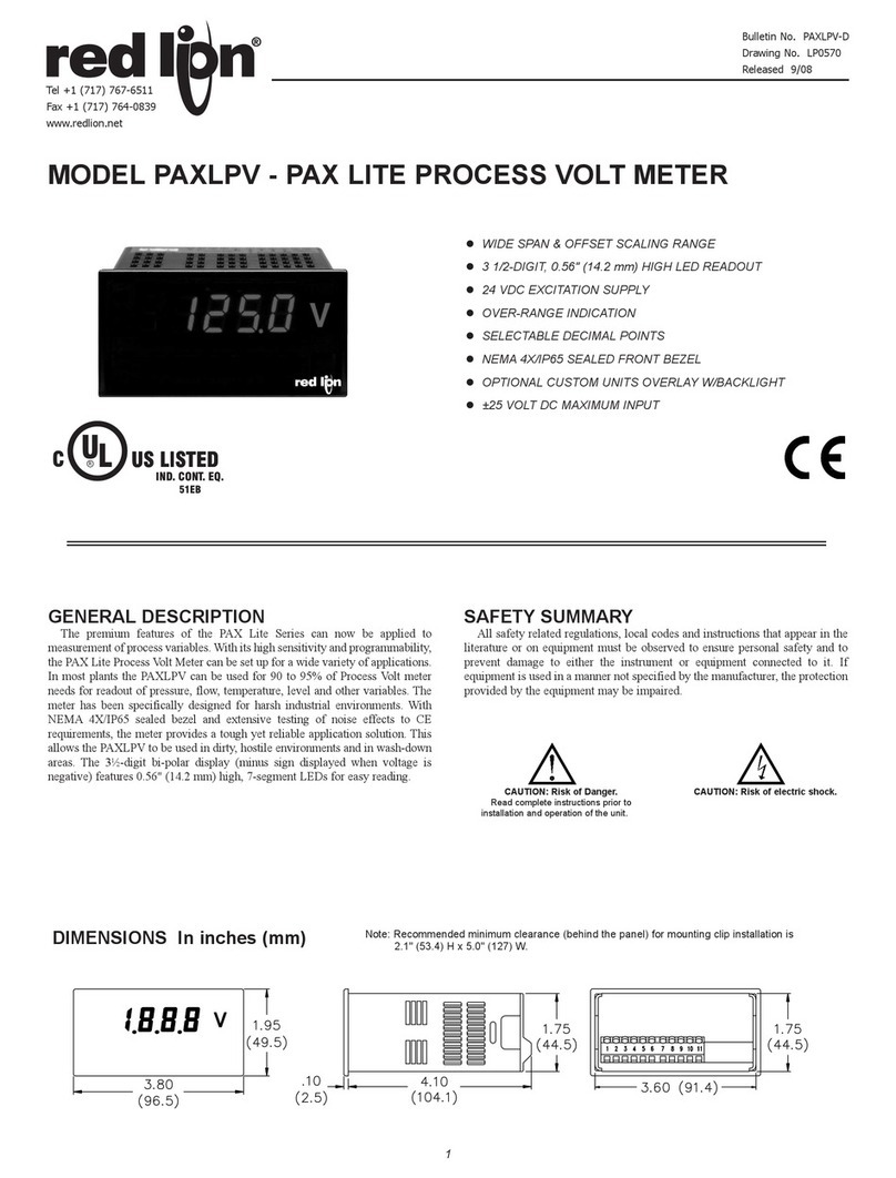
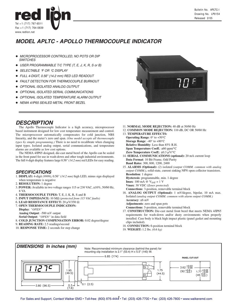
red lion APLTC User manual

red lion

red lion APLTC User manual

red lion IMP User manual

red lion

red lion IMP User manual

red lion CUB5V User manual

red lion

red lion CUB5V User manual

red lion LD Series User manual

red lion

red lion LD Series User manual

red lion APOLLO IMR Series User manual

red lion

red lion APOLLO IMR Series User manual

red lion APOLLO User manual

red lion

red lion APOLLO User manual

red lion CUB5RT User manual

red lion

red lion CUB5RT User manual

red lion PAX2D User manual

red lion

red lion PAX2D User manual

red lion PAXLR-PAX User manual

red lion

red lion PAXLR-PAX User manual

red lion CUB4TC User manual

red lion

red lion CUB4TC User manual

red lion IMD1 User manual

red lion

red lion IMD1 User manual

red lion PAXT0010 User manual

red lion

red lion PAXT0010 User manual

red lion PAXLR User manual

red lion

red lion PAXLR User manual

red lion PAX2D User manual

red lion

red lion PAX2D User manual

red lion PM500D0400800F00 User manual

red lion

red lion PM500D0400800F00 User manual

red lion PM-50 User manual

red lion

red lion PM-50 User manual

red lion APOLLO IMH Series User manual

red lion

red lion APOLLO IMH Series User manual

red lion DP5 User manual

red lion

red lion DP5 User manual

red lion PAXDP User manual

red lion

red lion PAXDP User manual

red lion PAXL series User manual

red lion

red lion PAXL series User manual

red lion APLR User manual

red lion

red lion APLR User manual

red lion PAXLPT User manual

red lion

red lion PAXLPT User manual

red lion PAX Lite PAXLHV User manual

red lion

red lion PAX Lite PAXLHV User manual

red lion CUB5 Series User manual

red lion

red lion CUB5 Series User manual

Popular Measuring Instrument manuals by other brands

Civacon ROM II troubleshooting guide

Civacon

Civacon ROM II troubleshooting guide

horiba 9681-10D instruction manual

horiba

horiba 9681-10D instruction manual

Hach FL1500 Basic user manual

Hach

Hach FL1500 Basic user manual

geo-FENNEL FL 115H user manual

geo-FENNEL

geo-FENNEL FL 115H user manual

Unipulse F340A Operation manual

Unipulse

Unipulse F340A Operation manual

Thermo Scientific iCAP 6000 Series Maintenance manual

Thermo Scientific

Thermo Scientific iCAP 6000 Series Maintenance manual

Tanita InnerScan PRO RD-953 user manual

Tanita

Tanita InnerScan PRO RD-953 user manual

YOKOGAWA 751552 user manual

YOKOGAWA

YOKOGAWA 751552 user manual

PCE Instruments PCE-423 manual

PCE Instruments

PCE Instruments PCE-423 manual

Atten AT5010 operating instructions

Atten

Atten AT5010 operating instructions

Hioki CT6700 instruction manual

Hioki

Hioki CT6700 instruction manual

Midtronics PBT-100 AP instruction manual

Midtronics

Midtronics PBT-100 AP instruction manual

hager tebis TX100 manual

hager

hager tebis TX100 manual

Swoffer Instruments 2200-3000 instruction manual

Swoffer Instruments

Swoffer Instruments 2200-3000 instruction manual

Hi-Target V90 Plus manual

Hi-Target

Hi-Target V90 Plus manual

Interacoustics ad226 Instructions for use

Interacoustics

Interacoustics ad226 Instructions for use

Keysight V3500A user guide

Keysight

Keysight V3500A user guide

Bender ISOMETER IR1575PG1 manual

Bender

Bender ISOMETER IR1575PG1 manual

manuals.online logo
manuals.online logoBrands
  • About & Mission
  • Contact us
  • Privacy Policy
  • Terms and Conditions

Copyright 2025 Manuals.Online. All Rights Reserved.