SPECIFICATIONS
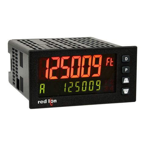
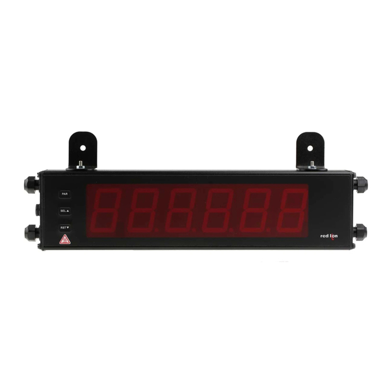
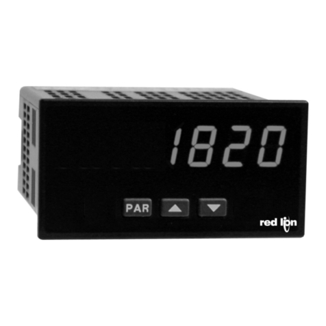
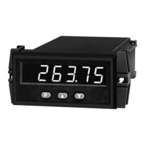
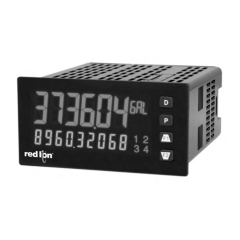
1. DISPLAY: 6 digit, 0.56" (14.2 mm) red LED
2. POWER:
AC Versions (PAXI0000):
AC Power: 85 to 250 VAC, 50/60 Hz, 18 VA
Isolation: 2300 Vrms for 1 min. to all inputs and outputs. (300 V working)
DC Versions (PAXI0010):
DC Power: 11 to 36 VDC, 14W
(Derate operating temperature to 40°C if operating <15 VDC and three
Plug-in cards are installed)
AC Power: 24 VAC, ± 10%, 50/60 Hz, 15 VA
Isolation: 500 Vrms for 1 min. to all inputs and outputs (50 V working)
3. SENSOR POWER: 12 VDC, ±10%, 100 mA max. Short circuit protected.
4. ANNUNCIATORS:
A - Counter A
B - Counter B
C - Counter C
!- Rate
"- Maximum (High) Rate
#- Minimum (Low) Rate
$% - Upper significant digit display of counter
SP1 - Setpoint 1 Output State
SP2 - Setpoint 2 Output State
SP3 - Setpoint 3 Output State
SP4 - Setpoint 4 Output State
5. KEYPAD: 3 programmable function keys, 5 keys total.
6. RATE DISPLAY:
Accuracy: ± 0.01%
Minimum Frequency: 0.01 Hz
Maximum Frequency: see Max Signal Frequencies Table.
Maximum Display: 5 digits: 99999
Adjustable Display (low) Update: 0.1 to 99.9 seconds
Over Range Display: “r OLOL”
7. COUNTER DISPLAYS:
Maximum display: 8 digits: ± 99999999 (greater than 6 digits display
alternates between high order and low order.)
8. INPUTS A and B:
DIP switch selectable to accept pulses from a variety of sources including
switch contacts, outputs from CMOS or TTL circuits, magnetic pickups
and all standard RLC sensors.
LOGIC: Input trigger levels VIL = 1.5 V max.; VIH = 3.75 V min.
Current sinking: Internal 7.8 KΩpull-up to +12 VDC, IMAX = 1.9 mA.
Current sourcing: Internal 3.9 KΩpull-down, 7.3 mA max. @ 28 VDC,
VMAX = 30 VDC.
Filter: Damping capacitor provided for switch contact bounce. Limits
input frequency to 50 Hz and input pulse widths to 10 msec. minimum.
MAGNETIC PICKUP:
Sensitivity: 200 mV peak
Hysteresis: 100 mV
Input impedance: 3.9KΩ@ 60 Hz
Maximum input voltage: ± 40 V peak, 30 Vrms
DUAL COUNT MODES:
When any dual count mode is used, then User Inputs 1 and/or 2 will accept
the second signal of each signal pair. The user inputs do not have the
Logic/Mag, HI/LO Freq, and Sink/Source input setup switches. The user
inputs are inherently a logic input with no low frequency filtering. Any
mechanical contacts used for these inputs in a dual count mode must be
debounced externally. The user input may only be selected for sink/source
by the User Jumper placement.
9. USER INPUTS: Three programmable user inputs
Max. Continuous Input: 30 VDC
Isolation To Sensor Input Commons: Not isolated
Logic State: Jumper selectable for sink/source logic
Response Time: 6 msec. typical; function dependent. Certain resets, stores
and inhibits respond within 25 µsec if an edge occurs with the associated
counter or within 6 msec if no count edge occurs with the associated
counter. These functions include &'!('#, &'!('), *+"*,', ('$!), and
-!+!('. Once activated, all functions are latched for 50 msec min. to 100
msec max. After that period, another edge/level may be recognized.
10. PRESCALER OUTPUT:
NPN Open Collector: ISNK = 100 mA max. @ VOL = 1 VDC max. VOH = 30
VDC max. With duty cycle of 25% min. and 50% max.
11. SERIAL COMMUNICATIONS CARD: Field installable plug-in card
RS485 or RS232 Card:
Isolation To Sensor & User Input Commons: 500 Vrms for 1 min.
Working Voltage: 50 V. Not Isolated from all other commons.
Data: 7/8 bits
Baud: 300 to 19,200
Parity: no, odd or even
Bus Address: Selectable 0 to 99, Max. 32 meters per line (RS485)
Transmit Delay: Selectable for 2 to 50 msec. or 50 to 100 msec.
MODBUS Card:
Type: RS485; RTU and ASCII MODBUS modes
Isolation To Sensor & User Input Commons: 500 Vrms for 1 min.
Not isolated from all other commons.
Baud Rates: 300, 600, 1200, 2400, 4800, 9600, 19200 and 38400.
Addresses: 1-247.
Format: 7/8 bits, odd, even and no parity
Transmit Delay: Programmable
12. ANALOG OUTPUT CARD: Field installable plug-in card
Available Outputs: 0 to 20 mA, 4 to 20 mA, or 0 to 10 VDC
Isolation To Sensor & User Input Commons: 500 Vrms for 1 min.
Working Voltage: 50 V. Not Isolated from all other commons.
Accuracy: 0.17% of FS (18 to 28°C); 0.4% of FS (0 to 50°C)
Resolution: 1/3500
Compliance: 10 VDC: 10 KΩload min., 20 mA: 500 Ωload max.
Response Time: 50 msec. max., 10 msec. typ.
13. SETPOINT OUTPUT CARD: Field installable plug-in card
Type: Two FORM-C relays
Isolation To Sensor & User Input Commons: 2000 Vrms for 1 min.
Working Voltage: 240 Vrms
Contact Rating:
One Relay Energized: 5 amps @ 120/240 VAC or 28 VDC (resistive load),
1/8 HP @ 120 VAC, inductive load
Total current with both relays energized not to exceed 5 amps
Life Expectancy: 100 K cycles min. at full load rating. External RC
snubber extends relay life for operation with inductive loads
Response Time: 5 msec. nominal with 3 msec. nominal release
Time Accuracy: Counter = ± 0.01% + 10 msec.
Rate = ± 0.01% + 20 msec.
Quad Relay Card:
Type: Four FORM-A relays
Isolation To Sensor & User Input Commons: 2300 Vrms for 1 min.
Working Voltage: 250 Vrms
Contact Rating:
One Relay Energized: 3 amps @ 250 VAC or 30 VDC (resistive load),
1/10 HP @ 120 VAC, inductive load
Total current with both relays energized not to exceed 4 amps
Life Expectancy: 100 K cycles min. at full load rating. External RC
snubber extends relay life for operation with inductive loads
Response Time: 5 msec. nominal with 3 msec. nominal release
Time Accuracy: Counter = ± 0.01% + 10 msec.
Rate = ± 0.01% + 20 msec.
Quad Sinking Open Collector Card:
Type: Four isolated sinking NPN transistors
Isolation To Sensor & User Input Commons: 500 Vrms for 1 min.
Working Voltage: 50 V. Not isolated from all other commons.
Rating: 100 mA max. @ VSAT = 0.7 V max. VMAX. = 30 V
Response Time: Counter = 25 µsec; Rate = Low Update time
Time Accuracy: Counter = ± 0.01% + 10 msec.
Rate = ± 0.01% + 20 msec.
Quad Sourcing Open Collector Card:
Type: Four isolated sinking PNP transistors
Isolation To Sensor & User Input Commons: 500 Vrms for 1 min.
Working Voltage: 50 V. Not isolated from all other commons.
Rating: Internal supply: 24 VDC ± 10%, 30 mA max. total
External supply: 30 VDC max. 100 mA each output
Response Time: Counter = 25 µsec. Rate = Low Update time
Time Accuracy: Counter = ± 0.01% + 10 msec.
Rate = ± 0.01% + 20 msec.
14. MEMORY: Non-volatile E2Prom retains all programming parameters and
display values. Exception: Max. and Min. rate values will only be stored if
Counter C is set for slave or none.
2
VIN > 2.5 VDC VIN < 0.7 VDC
Inactive
VIN < 0.7 VDC VIN > 2.5 VDC
Active
SINKING INPUTS
5.1 KΩΩpull-up to +12 V SOURCING INPUTS
5.1 KΩΩpull-down
INPUT STATE
