red roo TC350 Use and care manual

GT622
Commercial Environmental Equipment
Online Demonstration Available at: www.redroo.com/products/turfcutter
Operation, Safety & Maintenance Instructions
TC350
TURF CUTTER
- Hire A TurfcuTTer

© Copyright 2017
Red Roo Sales & Service Company Pty. Ltd.
1301-0059
2
INTRODUCTION
Dear Valued Customer,
Congratulations! You have purchased one of the most superbly
crafted Turf Cutters in the world. Properly maintained, it will
give you years of reliable service. When the instructions in this
manual are adhered to, operation is safe and simple.
Red Roo Turf Cutters are built to withstand the most difcult
conditions. Designed with simplicity and safety in mind, this
Turf Cutter performs using precision engineered componentry
and the force of gravity.
The Red Roo Turf Cutter is designed to cut turf with ease and
precision. Its heavy duty construction and premium engine
provide the durability required for this application.
Thank you for purchasing this Red Roo product and remember
to operate it responsibly and safely.
For your future reference
Serial No. Date of Purchase

3
TABLE OF CONTENTS
RED ROO SALES & SERVICE COMPANY PTY. LTD
41-43 Keysborough Avenue, Keysborough, Victoria, Australia 3173
Tel.: +61 (03) 9769 0455 Fax: +61(03) 9769 0366
Outside Melbourne Metro: Tel.: 1300 133 767 Fax: 1300 133 757
www.redroo.com
ABOUT THIS MANUAL 4
SAFETY INSTRUCTIONS 5
OPERATING INSTRUCTIONS 6
TC350 DIAGRAM 7
CARING FOR YOUR POWDERCOAT FINISH 8
TC350 ILLUSTRATION 9
TC350 PARTS LIST 10
TC350 PARTS LIST 11
TC350 PARTS LIST 12
TC350 SERVICING HISTORY 13
WARRANTY POLICY 14

ABOUT THIS MANUAL
The information contained in this manual has been prepared to assist you in the safe operation, the routine
maintenance and general care of your Red Roo product. By following these guidelines, you may look forward to
years of reliable service from your Red Roo. Information is categorised and denoted by the following symbols
and phrases:
SAFETY FIRST Identies general safety practices.
Before operating this Machine read
and observe all Warnings, Cautions
and Instructions on the Machine and
in the Operators Manual. Although the
reading of information contained in
this manual does not eliminate the risk
involved in operating this machine,
your understanding of this information
will promote the correct and safe use
of your machine. Failure to follow
Instructions and Safety Information
could result in serious injury or death.
An instruction which, if not followed, could result in serious or fatal injury
An instruction which, if not followed, could result in personal injury.
An instruction which, if not followed, could result in the possibility of
personal injury or damage to machine compnents.
DANGER!
WARNING!
CAUTION!
SAFETY FIRST
The TC350 Turf Cutter is designed to cut turf and therefore is potentially dangerous.
Careless or improper use may cause serious or even fatal injury.
It is important that you read and understand the contents of both this manual and the engine manual.
Allow only mature, adult individuals to operate your turf cutter. It is your responsibility to ensure
that any individual who operates your turf cutter has read and understood these manuals.
Never use the turf cutter for any other purpose than cutting turf. The machine is designed explicitly for
this purpose and this purpose only. Any other use may result in serious or fatal injury and/or damage
to the machine.
Read this section before use!
4

SAFETY INSTRUCTIONS
1) DO NOT allow any person to operate the turf cutter without rst reading and understanding the safety
and operating instructions.
KNOW THE CONTROLS & HOW TO STOP THE TURFCUTTER QUICKLY IN AN EMERGENCY
2) NEVER allow CHILDREN or UNTRAINED ADULTS to operate the turf cutter
3) PPE (PERSONAL PROTECTION EQUIPMENT) IS MANDATORY BEFORE OPERATING THIS MACHINE
ALWAYS wear protective clothing when operating the turf cutter. This includes, but not limited to; safety
glasses, loose tting gloves, steel capped boots and hearing protection. NEVER wear loose tting clothing or
jewelry when operating the turf cutter. Keep all clothing away from moving parts. Clothing could become
caught in the machine resulting in injury.
4) ALWAYS operate the turf cutter in a well-lighted area
5) ALWAYS make certain that both control clutches are in the “DISENGAGED” position prior to starting the
engine.
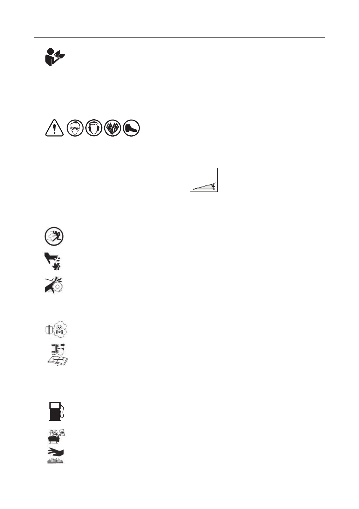
6) ALWAYS operate the turf cutter on level ground only.
Keep your work area clear and free of of debris.
DO NOT operate on angle that exceeds 15º degrees.
7) NEVER operate the turf cutter when fatigued. ALWAYS BE ALERT! If you get tired while operating the turf
cutter take a break. If you have any type of physical or mental condition that may be aggravated by
strenuous work, consult with your physician before operating this piece of equipment. NEVER operate
the turf cutter under the inuence of medication, alcohol or drugs.
8) DO NOT allow other adults, children or animals near the turf cutter. IT IS THE RESPONSIBILITY OF
THE OPERATOR to keep bystanders and animals a minimum of 6 metres (18 feet) away from the turf
cutter while in operation.
9) ALWAYS KEEP YOUR HANDS, FEET, AND BODY AWAY FROM TURF CUTTING ZONE WHILE
THE ENGINE IS RUNNING
10) NEVER remove the safety guarding attached to the turf cutter. These protective devices must be in
place
and in good working order at all times during the operation of this machine. Keep the unit well
maintained
and in good working order.
11) DO NOT leave the machine unattended while the engine is running.
12) DO NOT over speed the engine or alter the governor settings.
Excessive speed is dangerous and will shorten engine life.
13) NEVER OPERATE THE TURF CUTTER IN AN ENCLOSED AREA.
Engine exhaust contains carbon monoxide, an odourless and tasteless poison that can kill
14) STOP the engine, disconnect the spark plug leads and allow engine to cool before inspecting or
performing maintenance
15) REFUELIING
• Shut off engine. DO NOT REFUEL AN ENGINE WHILE OPERATING MACHINE!
• ALLOW engine to cool down. Minimum 5 minutes
• USE UNLEADED FUEL ONLY
• USE CLEAN FRESH UNLEADED FUEL
• Do not mix oil with unleaded fuel
• Do not over-ll fuel tank. Allow space for fuel expansion
• Do not smoke
• Allow no naked ame or hot material in refuelling area
• Use only approved fuel containers and funnels.
REMEMBER FUEL IS A POTIENTIAL FIRE HAZARD
5
MAXIMUM ANGLE
OF OPERATION
DO NOT EXCEED
15º ANGLE

1) Remove the turf cutter from its carrying vehicle or trailer.
ALWAYS USE CAUTION
2) Familiarize yourself with this turf cutter and its controls. Learn where all engine controls are and be prepared
to stop this machine quickly in a possible emergency.
3) PPE (PERSONAL PROTECTION EQUIPMENT) IS MANDATORY BEFORE OPERATING THIS MACHINE.
Wear safety glasses or helmet and visor combination, loose tting gloves, hearing protection, and steel caps
boots when operating this machine.
4) Before starting the engine, ensure the turf cutting blade is in the raised position.
5) Before starting the engine, ensure both clutch handles are forward and disengaged.
6) Move choke control to Choke or Start position:
NOTE: CHOKE MUST FULLY CLOSE.
MOVE THROTTLE CONTROL TO RUN OR FAST POSTION OPERATE ENGINE AT MAXIMUM RPMs
7) Maneuver the turf cutter to the area where the turf is to be removed. This can be done by pushing the turf
cutter or driving the machine using its own power, simply engage the wheel drive clutch and move the
machine to the desired cutting area.
8) When the operator is ready to start cutting turf, lower the turf cutting blade to the desired depth by lifting up on
the depth control handle.
9) Adjust the throttle lever (located on the engine) to achieve desired rpm (motor speed) according to the
conditions WARNING! KEEP HANDS AND FEET CLEAR OF TURF CUTTING BLADE AT ALL TIMES
10) To start the turf cutting blade slowly push the blade engagement clutch lever towards the engine.
11) Only after the turf cutter blade has been lowered and the blade engagement clutch lever has been activated
are you ready to engage the wheel drive clutch lever.
12) Completely Engage the self propelled wheel drive clutch lever
WARNING! IN CASE OF DIFFICULTY, DISENGAGE BOTH CLUTCH LEVERS (ALL ACTION STOPS)
TURN THE ENGINE SWITCH TO OFF LOCATED ON HANDLE BAR OR ENGINE
13) When you are nished cutting the turf, reverse the procedure:
a) Reduce the throttle speed
b) Disengage self-propelled clutch – pull backwards toward operator
c) Disengage turf cutting blade – pull backwards toward operator
d) Raise the turf cutting blade
e) Engage the self-propelled clutch lever and return to the trailer/carrier
f) Use Caution
14) STOP ENGINE: Do not move the choke control to the CHOKE position to stop the engine.
15) Move throttle control to the slow position
AFTER USE
1) Turn fuel tap to the off position
2) Allow the machine to cool down
3) Keep the machine clean using warm soapy water. Make sure that no water enters the carburetor
4) Remove any weeds, wire, rope, etc. that may have wrapped around the cutting assembly
OPERATING INSTRUCTIONS
6

OPERATOR ZONE
On / Off Switch
Engine ExhaustLifting Point
Bumper Bar
Engine
On / Off
Switch
Wheel Drive
Engagement
Clutch Lever
Turf Cutter Blade
Depth
Control
Handle
Turf Cutter
Blade Engage / Disengage
Clutch Lever
7
TURF CUTTING ZONE
safety
...now
IS EVERYBODY’S BUSINESS
You alone know the operational demands
and special conditions affecting the
equipment in to your situation and therefore
assume the responsibility for developing,
carrying out, and enforcing the safety
concepts which apply to your own operation
to effect the greatest safety for yourself and
the people around you.

STORAGE
The effects of ultra violet light, pollution, dirt, grime, and salt deposits accumulate on the powder coated surface
of your machine over time. To extend the effective life of the powder coated surface, a regular maintenance
program should be implemented for the removal of any debris or residues.
As a general rule the machine should be cleaned after every use.
1) Remove any loose deposits with a wet sponge
2) Use a soft brush (non abrasive) or cloth, & a mild household detergent solution to remove any dirt, or grime
3) Pressure wash or rinse when nished
Detergents that recommend the use of gloves when handling should be avoided. The detergent may be
too harsh and therefore unsuitable for cleaning your powder coating. Although some strong solvents are
recommended for removing grease, or other stubborn residues these may be harmful to the extended life of
the powder coated surface. If paint splashes or other residue needs to be removed then use methylated spirits,
turpentine or white spirits.
When unit is not in use, store out of the reach of children. Ensure that petrol fumes are not present in the storage
area. For extensive storage periods, the fuel tank should be drained or a fuel stabiliser added. Draining the tank
is strongly recommended. Engine should be stored with the intake and exhaust valves closed (compression
stroke). See Engine Manual.
www.redroo.com
8
CARING FOR YOUR POWDERCOATED FINISH

1
1
2
2
3
3
4
4
5
5
6
6
A A
B B
C C
D D
DRAWN TO AS1100
DIMENSIONS IN MILLIMETRES
www.redroo.com
REMOVE ALL BURRS & SHARP EDGES * NO SCRATCHES * For Holes Profiles/Cutout Sizes & Positions Use Supplied DXF or STEP File
All Drawings are
Subject to Engineers Approval
Checked by:
J.Hyslop
Dwg by:
FABRICATION TOLERANCES
+61 408 030 780
+61 3 9769 0455
+61 3 9769 0366
Mobile
Telephone
Facsimile
.X
0.3mm
.XX
0.15mm
.XXX
0.05mm
ANGULAR
0.25mm
Finish:
15mm up to 250mm
0.2mm
250mm up to 500mm
0.3mm
500mm and over
0.5mm
MACHINING TOLERANCES
Material:
UNLESS OTHERWISE NOTED
THIRD ANGLE PROJECTION
Drawing / Part Number:
Title:
TC350 - Main - Assembly
Cad File Name:
ANGULAR
1
4/02/2014
Date:
Sheet
/
Edition:
83
2
G.Lute
As Nominated
As Nominated
TC350 - Main - Assembly [ Guard Removed ]
N/A
1
2
1
2
3
5
9
10
12
12
11
13
16
15
17
18
21 101
101
19
23
24
25
26
28
31
38
102
104
65
1Parts List Updated & Mods Dated 30-10-14 30-10-14
1
1
2
2
3
3
4
4
5
5
6
6
A A
B B
C C
D D
DRAWN TO AS1100
DIMENSIONS IN MILLIMETRES
www.redroo.com
REMOVE ALL BURRS & SHARP EDGES * NO SCRATCHES * For Holes Profiles/Cutout Sizes & Positions Use Supplied DXF or STEP File
All Drawings are
Subject to Engineers Approval
Checked by:
J.Hyslop
Dwg by:
FABRICATION TOLERANCES
+61 408 030 780
+61 3 9769 0455
+61 3 9769 0366
Mobile
Telephone
Facsimile
.X
0.3mm
.XX
0.15mm
.XXX
0.05mm
ANGULAR
0.25mm
Finish:
15mm up to 250mm
0.2mm
250mm up to 500mm
0.3mm
500mm and over
0.5mm
MACHINING TOLERANCES
Material:
UNLESS OTHERWISE NOTED
THIRD ANGLE PROJECTION
Drawing / Part Number:
Title:
TC350 - Main - Assembly
Cad File Name:
ANGULAR
1
4/02/2014
Date:
Sheet
/
Edition:
83
2
G.Lute
As Nominated
As Nominated
TC350 - Main - Assembly [ Guard Removed ]
N/A
1
2
1
2
3
5
9
10
12
12
11
13
16
15
17
18
21 101
101
19
23
24
25
26
28
31
38
102
104
65
1Parts List Updated & Mods Dated 30-10-14 30-10-14
TC350 TURF CUTTER ILLUSTRATION 1
9

safety
...now
IS EVERYBODY’S BUSINESS
You alone know the operational demands
and special conditions affecting the
equipment in to your situation and therefore
assume the responsibility for developing,
carrying out, and enforcing the safety
concepts which apply to your own operation
to effect the greatest safety for yourself and
the people around you.
PARTS LIST FOR TC350 TURF CUTTER
Part No.Item No. Description Quantity
1 0503-0007 Honda Ending 1
2 0605-0043 Main Body 1
3 0801-0027 Depth Control Handle 1
4 0202-0006 Belt Adjust - Engine Mount Bar 1
5 0704-0058 Bumper Bar 1
6 N/A Cutter Engagement Swing Arm 1
7 N/A Wheel Engagement Swing Arm 1
8 0801-0022 Main Handle 1
9 2305-0018 Front Wheel 2
10 2507-0007 Pull Rod Linkage - Clip 2
11 0214-0126 Belt Guard Front Mount 1
12 0214-0125 Belt Guard Bracket 2
13 0206-0023 Blade Turf Cutter 1
14 N/A Crank Arm 2
15 1808-0031 Pull Rod Wheel Engagement - RH 1
16 1808-0032 Pull Rod Cutter Engagement - LH 1
17 0801-0024 LH Side Cutter Drive Engagement 1
18 0801-0026 RH Side Wheel Drive Engagement 1
19 0705-0013 Belt Guide Upper Cutter Drive Pulley 1
21 0705-0014 Guide Rear & Crank Pulley 1
22 0705-0011 Belt Guide - Front Wheel 1
23 0102-0017 Side Swing Arm Blade Holder 2
24 1904-0030 Front Axle 1
25 1904-0029 Rear Axle 1
26 1904-0032 Pivot Bar For Controls 1
27 1913-0028 Countershaft - Eccentric Boss 2
28 1904-0027 Countershaft 1
29 0704-0055 Guard Belt 1
30 0215-0041 Bush - Depth Control Pivot 1
31 2302-0019 Back Wheel Assy 4
10

safety
...now
IS EVERYBODY’S BUSINESS
You alone know the operational demands
and special conditions affecting the
equipment in to your situation and therefore
assume the responsibility for developing,
carrying out, and enforcing the safety
concepts which apply to your own operation
to effect the greatest safety for yourself and
the people around you.
PARTS LIST FOR TC350 TURF CUTTER
Part No.Item No. Description Quantity
32 1904-0025 Swing Shaft - Side Arms 1
33 1608-0041 Small Wheel Drive Pulley 1
34 1608-0040 Counter Shaft Pulley 1
35 1608-0042 Engine Pulley 1
36 1904-0031 Shaft Reduction Idler Pulley 1
38 1608-0037 Main Drive Pulley 1
39 1608-0038 Wheel Drive Pulley 1
41 0806-0033 Idler Shaft Bearing Assy 2
42 0806-0032 Front Wheel Bearing Assy 2
43 0806-0031 Crank Shaft Bearing Assy 2
57 0209-0108 Bolt 7
58 2301-0004 Washer 3
59 2301-0021 Washer 11
60 0209-0620 Bolt 4
62 2301-0013 Washer 14
63 0209-0619 Bolt 4
64 1401-0074 Nut 10
65 0209-0041 Bolt 2
66 0209-1511 Bolt 1
67 2301-0040 Washer 1
68 1401-0513 Nut 1
69 0209-0321 Bolt 4
71 1401-0033 Nut 8
72 0209-0520 Bolt 2
73 2301-0008 Washer 4
74 0209-1025 Bolt 2
75 1401-0511 Nut 3
76 2301-0507 Washer 5
78 0209-0350 Bolt 1
79 0209-0535 Bolt 2
11

82 1401-0053 Nut 2
84 1401-0023 Nut 7
85 0209-0422 Bolt 1
86 0209-0025 Bolt 2
88 2301-0007 Washer 5
90 1401-0043 Nut 3
91 0209-0142 Bolt 1
92 1401-0011 Nut 3
95 1604-0026 Pin 2
96 0209-0115 Bolt 1
97 2301-0018 Washer 13
98 1901-0804 Screw 1
100 0209-0127 Bolt 4
101 0705-0012 Belt Guide - Lower Driven Pulley 2
102 0313-0002 Document Holder 1
104 1923-0002 On - Off Toggle Switch 1
safety
...now
IS EVERYBODY’S BUSINESS
You alone know the operational demands
and special conditions affecting the
equipment in to your situation and therefore
assume the responsibility for developing,
carrying out, and enforcing the safety
concepts which apply to your own operation
to effect the greatest safety for yourself and
the people around you.
PARTS LIST FOR TC350 TURF CUTTER
Part No.Item No. Description Quantity
12

DATE PART No. COMMENTS
TC350 TURF CUTTER - SERVICE HISTORY
13
PLEASE USE ONLY GENUINE
RED ROO SPARE PARTS

“For a time period shown below from date of purchase, pending owner registration, Red Roo Sales &
Service Company, P/L, herein referred to as “MANUFACTURER”, will, at its option, repair or replace
for the original purchasers of new Red Roo equipment, free of charge, any part, or parts of the unit
(excluding Power Unit, warranty coverage provided by respective engine manufacturer), found upon
inspection and testing by a Factory Authorised Agent, or by the Factory at Keysborough, Victoria, to be
defective in material or workmanship or both under normal operating conditions; this is the exclusive
remedy. All transportation charges on parts submitted to the MANUFACTURER for replacement under
this Warranty are the responsibility of the purchaser.
This Warranty shall not apply to any product that has been altered, modied, or operated in a manner
not approved or recommended by the MANUFACTURER, Warranty will be null and void in the
following circumstances: (1) repairs or attempted repairs have been performed by persons other than
agents authorised by the MANUFACTURER (2) repairs are required because of normal wear; (3) the
unit has been subject to abuse or involved in an accident; (4) misuse is evident, such as that caused
by an application that unit is not intended to perform.
The MANUFACTURER reserves the right to modify, alter, or otherwise improve any product or part.
The purchaser is responsible for the performance of regular maintenance services as specied in the
operator manual applicable to the unit. Untimely and/or improper care and replacement of normal
maintenance items (eg: lters, belts, drive chains, blades, knives, lubricants) may void Warranty, Use
of non genuine Red Roo parts may void Warranty.
THERE IS NO OTHER EXPRESS WARRANTY. IMPLIED WARRANTIES, INCLUDING THOSE
OF MERCHANTABILITY AND FITNESS FOR A PARTICULAR PURPOSE ARE LIMITED TO 14
DAYS FROM PURCHASE, AND TO THE EXTENT PERMITTED BY LAW ANY AND ALL IMPLIED
WARRANTIES ARE EXCLUDED. LIABILITY FOR CONSEQUENTIAL DAMAGES UNDER ANY AND
ALL WARRANTIES ARE EXCLUDED TO THE EXTENT EXCLUSION IS PERMITTED BY LAW. RED
ROO GROUP OF COMPANIES DOES NOT AUTHORISE ANY PERSON OR ENTITY TO CREATE
FOR IT ANY OTHER OBLIGATION OR LIABILITY IN CONNECTION WITH ITS PRODUCTS OR
SERVICES.
Some states do not allow limitations on how long an implied warranty lasts, and some states do
not allow the exclusion of limitation of incidental or consequential damages, so the above limitation
exclusion may not apply to you. This warranty gives you specic legal rights and you may also have
other rights which vary from state to state.”
Red Roo Sales & Service Company, P/L
James A. Kerr III
Managing Director
Warranty Period
All Equipment Consumer Use*
365 Days
Commercial Use*
90 Days
* For the purposes of this warranty policy, “consumer use” shall mean personal residential household
use by the original retail consumer. “Commercial use” shall mean all other uses, including use for
commercial, income producing or hire purposes. Once a unit has experienced commercial use, it shall
thereafter be considered as a commercial use unit for purposes of this warranty policy.
Proper registration of your Red Roo equipment is required to obtain warranty service. It is the
responsibility of the original purchaser to register equipment within 10 days of purchase.
Superseding Warranty
Red Roo Group of Companies
Warranty Policy
effective December 19th, 2017
Replaces all undated previous Warranties and all Warranties dated prior to December 19th, 2017.
14
Other manuals for TC350
1
Table of contents
Other red roo Cutter manuals