REDALERT 393-001AD User manual

Pub. 42004-472B
GAI-Tronics Corporation 400 E. Wyomissing Ave. Mohnton, PA 19540 USA
610-777-1374 800-492-1212 Fax: 610-796-5954
VISIT WWW.GAI-TRONICS.COM FOR PRODUCT LITERATURE AND MANUALS
GAI-TRONICS® CORPORATION
A HUBBELL COMPANY
Auto-Dial Telephones Manual
TABLE OF CONTENTS
Confidentiality Notice.....................................................................................................................1
Product Overview............................................................................................................................1
Telephones...............................................................................................................................................1
Telephone Management Application (TMA) .......................................................................................2
Standard Operation.........................................................................................................................4
Receiving a Call.......................................................................................................................................4
Disconnecting a Call ...............................................................................................................................4
Location Identification Code Dialing....................................................................................................4
Installation ......................................................................................................................................5
Safety Guidelines.....................................................................................................................................5
General Installation Guidelines.............................................................................................................6
Security Hardware..................................................................................................................................6
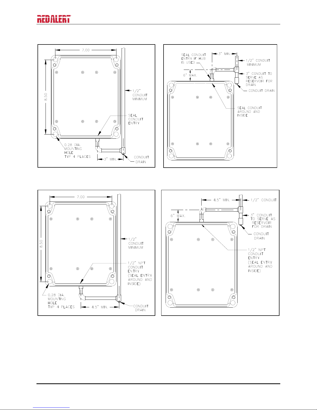
Conduit Installation Details...................................................................................................................6
Models 393-00xAD and 393AL-00xAD.................................................................................................8
Model 397-00xAD..................................................................................................................................10
Stanchion or Flush-Mount Applications .............................................................................................................10
External Power for –003AD Models....................................................................................................13
Connecting a Model 530 Series Strobe................................................................................................13
Setup..............................................................................................................................................14
Hardware Configuration......................................................................................................................14
Auto-answer Configuration ................................................................................................................................14
Polarity Configuration ........................................................................................................................................14
DTMF Gain Select Configuration.......................................................................................................................14
Password Enable Configuration..........................................................................................................................15
Command Select Configuration..........................................................................................................................15
Low-Power Mode Configuration ........................................................................................................................15
Hardware Settings...............................................................................................................................................15
Auxiliary Outputs.................................................................................................................................16
Extreme Cold Temperature Option....................................................................................................17
Auxiliary Output Control.....................................................................................................................18

PUB.42004-472B
AUTO-DIAL TELEPHONE MANUAL
GAI-Tronics Corporation 400 E. Wyomissing Ave. Mohnton, PA 19540 USA
610-777-1374 800-492-1212 Fax: 610-796-5954
VISIT WWW.GAI-TRONICS.COM FOR PRODUCT LITERATURE AND MANUALS
Standard Mode Programming......................................................................................................20
Set-up Sequence ....................................................................................................................................20
Remote................................................................................................................................................................20
Local ...................................................................................................................................................................20
Programming Sequence........................................................................................................................21
Password Disabled Programming.......................................................................................................21
Programming Sequences......................................................................................................................22
Dialing Options...................................................................................................................................................22
Password Protection............................................................................................................................................24
Auto-Answer Alert Feature.................................................................................................................................24
Disconnect Options.............................................................................................................................................25
Americans with Disabilities Act (ADA) Programming ......................................................................................26
Extended Strobe Operation (Requires External Power Supply)..........................................................................26
Output 4 Control Setup .......................................................................................................................................27
Early Microphone Option ...................................................................................................................................28
SMART Mode Programming........................................................................................................30
Maintenance..................................................................................................................................30
Service....................................................................................................................................................30
Preventive Maintenance for Flush-Mount Telephones .....................................................................30
Cleaning..............................................................................................................................................................30
Prevention ...........................................................................................................................................................30
Specifications ................................................................................................................................31

PUB.42004-472B
GAI-Tronics Corporation 400 E. Wyomissing Ave. Mohnton, PA 19540 USA
610-777-1374 800-492-1212 Fax: 610-796-5954
VISIT WWW.GAI-TRONICS.COM FOR PRODUCT LITERATURE AND MANUALS
GAI-TRONICS® CORPORATION
A HUBBELL COMPANY
Auto-Dial Telephones Manual
Confidentiality Notice
This manual is provided solely as an operational, installation, and maintenance guide and contains
sensitive business and technical information that is confidential and proprietary to GAI-Tronics. GAI-
Tronics retains all intellectual property and other rights in or to the information contained herein, and
such information may only be used in connection with the operation of your GAI-Tronics product or
system. This manual may not be disclosed in any form, in whole or in part, directly or indirectly, to any
third party.
Product Overview
Telephones
RED ALERT®series Auto-dial (AD series) Telephones have been designed for maximum environmental
sustainability and high audio quality. The AD series telephones provide reliable, hands-free, two-way
communications in nearly any environment as all models are rated Type 3R. The AD series products are
intended for a single-button call activation telephone in a non-emergency environment.
Each AD series telephone complies with the Americans with Disabilities Act (ADA) in both physical and
operational characteristics. Each telephone includes a Braille label for vision-impaired individuals for
identifying the “call” function of the telephone and a visual CALL RECEIVED WHEN LIT LED for
hearing-impaired individuals. The LED will flash when the CALL button is pressed (call in progress) and
will provide a steady illumination when the call has been answered. The LED will remain illuminated
until the call has been terminated.
The CALL button on each telephone can be programmed to dial three different telephone numbers. These
include a primary telephone number and two “rollover” telephone numbers. In the event that the first
number goes unanswered or is busy, the telephone will automatically dial the first rollover number. The
second rollover number will be dialed if the first rollover number cannot connect. This feature is
completely programmable.
All RED ALERT®Auto-dial series Telephones are line-powered and can be connected to any of the
following networks:
Central Office (C.O.) line to the Public Switched Telephone Network (PSTN)
24 V dc or 48 V dc analog station port of a Private Branch Exchange (PBX), Private Automatic
Branch Exchange (PABX), or Key Service Unit (KSU).
NOTE:Connection to pay telephone extensions or shared service (party) lines should be avoided.

PUB.42004-472B
AUTO-DIAL TELEPHONE MANUAL PAGE 2 of 33
f:\standard ioms - current release\42004 instr. manuals\42004-472b.doc
01/15
Each telephone requires a minimum line current of 24 mA for proper operation. For operation below
−4º F (−20° C), GAI-Tronics offers an Extreme Cold Weather Option that includes a plug-in power
supply (120 V ac required) and a non-tactile CALL push button. This option will allow reliable operation
to −40° C/F.
The RED ALERT®Auto-dial series Telephones provide the flexibility to address a diverse range of
applications. A wide variety of functions can be achieved by altering the configuration data stored in the
telephone’s non-volatile memory. These configuration options include:
Pre-programmed auto-dial telephone numbers
Call termination method (automatic or manual)
Maximum call duration
Answering options
Values for these functions are initially programmed during factory testing, but can be changed remotely
from a touch-tone telephone.
The following RED ALERT®Auto-dial Telephone models are detailed in this manual:
Table 1. Model Chart
Model Description
393-001AD Surface-Mount Telephone, single auto-dial push button, weatherproof glass-
reinforced polyester enclosure, safety yellow.
393-003AD Surface-Mount Telephone, single auto-dial push button, weatherproof glass-
reinforced polyester enclosure, safety yellow, Extreme Cold Weather option.
393AL-001AD Surface-Mount Telephone, single auto-dial push button, weatherproof cast
aluminum enclosure, safety yellow.
393AL-003AD Surface-Mount Telephone, single auto-dial push button, weatherproof cast
aluminum enclosure, safety yellow, Extreme Cold Weather option.
397-001AD Flush-Mount Emergency Telephone, single auto-dial push button, weatherproof
brushed stainless steel front panel.
397-003AD Flush-Mount Emergency Telephone, single auto-dial push button, weatherproof
brushed stainless steel front panel, Extreme Cold Weather option.
Telephone Management Application (TMA)
RED ALERT®Auto-dial series Telephones are also compatible with GAI-Tronics Telephone
Management Application (TMA) software package (purchased separately). TMA is a maintenance data
collection tool that allows users to view and report the health and activity of the AD telephones. The
decision to use TMA can be made at any time and it is not needed for telephone operation. Installation of
TMA is not required unless system monitoring is desired.

PUB.42004-472B
AUTO-DIAL TELEPHONE MANUAL PAGE 3 of 33
f:\standard ioms - current release\42004 instr. manuals\42004-472b.doc
01/15
When used with TMA, each telephone will typically be polled on a scheduled basis to determine its health
and will report the following:
Stuck push button
Microphone failure
Speaker failure
Microprocessor health (handshake)
Line interrupt (line current loss)
A dedicated telephone line is required per auto-dial telephone when the typical “polling” operation is
used. Although not recommended, auto-dial telephones can share a telephone line with the understanding
that if two or more telephones are put into use simultaneously, the line current could drop sufficiently to
disconnect the telephone call completely. This will depend on the line current, the length of the cable run,
and the condition of the telephone cable. When sharing a telephone line using TMA, the telephone must
be scheduled to “call in” instead of being polled by TMA.
The basic TMA package, Model 12509-042, includes a single line transceiver for polling a single
telephone at a time (dedicated telephone line required). A TMA expansion kit (Model 12509-043)
introduces an additional transceiver to the system for multiple simultaneous telephone polling. The
system will support up to eight transceivers. A dedicated telephone line is required for each transceiver.

PUB.42004-472B
AUTO-DIAL TELEPHONE MANUAL PAGE 4 of 33
f:\standard ioms - current release\42004 instr. manuals\42004-472b.doc
01/15
Standard Operation
1. Press the CALL push button to place an immediate call to a pre-programmed telephone number.
2. The CALL RECEIVED WHEN LIT indicator (LED) operates as follows:
The indicator will begin to flash when the CALL push button is pressed (call in progress) and will
illuminate steadily when the telephone detects audio after the call is answered.
- or -
The indicator will begin to flash when the CALL push button (call in progress) is pressed and will
illuminate steadily when the called party acknowledges receiving the call by transmitting a
DTMF “#” or “*” after answering the call.
3. Two-way, hands-free conversation can now occur.
Receiving a Call
Each RED ALERT®Telephone can be programmed to auto-answer an incoming call. When the auto-dial
telephone extension is dialed, the unit will automatically answer, generate a pair of triple “beep” tones,
and two-way, hands-free conversation can occur.
Disconnecting a Call
There are several methods by which a RED ALERT®Auto-dial Telephone can both manually and
automatically disconnect calls. The disconnect methods include the following:
Remote disconnect of a call – Called party transmits either a “##” or “*99” DTMF control
command.
Manual disconnect of a call – Press the CALL push button approximately 15 seconds after the initial
activation.
NOTE: Pressing the CALL push button a second time within 10 seconds of initially activating the
call will have no effect on the telephone’s operation. This prevents an anxious or hurried user from
disconnecting the call prematurely (this feature can be disabled).
Automatic disconnect:
-All calls; loop current-drop disconnect
-All calls; maximum call duration timeout (configurable from 1 minute to 4.5 hours)
-All voice calls; call progress tones (i.e., busy signal/fast busy, or reorder, tone) and, when enabled,
dial tone.
Refer to the “Programming” section of this manual for factory defaults and available options.
Location Identification Code Dialing
The Location Identification Code feature enables the called party to quickly and easily locate the source
of the auto-dial call. When the calling individual presses the CALL push button, the called party
(typically the security operator) presses the “*”button on their telephone. The AD Telephone detects the
“*” signal and transmits a three-digit, DTMF, location identification code. This location code can be
displayed on a customer-provided DTMF decoder/display.
Please refer to the “Americans with Disabilities Act (ADA) Programming” section on page 26.

PUB.42004-472B
AUTO-DIAL TELEPHONE MANUAL PAGE 5 of 33
f:\standard ioms - current release\42004 instr. manuals\42004-472b.doc
01/15
Installation
ATTENTION Installation should be performed by qualified personnel and only in
accordance with the National Electrical Code or applicable local codes.
Safety Guidelines
When installing any GAI-Tronics telephone equipment, please adhere to the following guidelines to
ensure the safety of all personnel:
Do not install telephone wiring during a lightning storm.
Electrostatic Discharge (ESD) Protection: Your telephone may have an earth ground terminal
provision. If so, ensure that it is connected to ground in accordance with all local safety regulations
and the National Electrical Code (NEC). Grounding has to be ensured for safe and stable
communications. Do not use long and coiled ground wires. Trim ground wires to the required
length. Use a star configuration whenever possible. Please note proper grounding does not eliminate
the need for lightning protection for the telephone or the telephone system.
Install a UL Listed lightning arrestor on any telephone installed where the telephone or telephone
cable is at risk of being exposed to lightning strikes. The lightning arrestor must be installed as close
to the telephone as possible to maximize the protection. It must not be installed within the enclosure
supplied with the telephone.
Do not install telephone jacks in wet locations unless the jack is specifically designed for wet
locations.
Do not touch uninsulated telephone wires or terminals unless the telephone line has been
disconnected at the network interface.

PUB.42004-472B
AUTO-DIAL TELEPHONE MANUAL PAGE 6 of 33
f:\standard ioms - current release\42004 instr. manuals\42004-472b.doc
01/15
General Installation Guidelines
As previously noted, the preferred system configuration is a dedicated telephone line per RED ALERT®
Telephone. This is an actual requirement when using TMA in its typical “polling” operation.
Although it is not recommended, a RED ALERT®Telephone can share a telephone line with another
RED ALERT®Telephone with the understanding that if two or more telephones are put into use
simultaneously the line current could drop sufficiently to disconnect the telephone call completely.
Additional “line sharing” or “party line” configuration issues could include sporadic telephone operation,
difficulties with programming, or premature disconnection of calls. Special system features (voice mail,
call waiting, etc.) could also create problems if not disabled. Successful shared line operation will depend
on the line current, the length of the cable run, and the condition of the telephone cable.
NOTE:A RED ALERT®Telephone should never be installed on the same telephone line as any
other (non-RED ALERT®) Telephone type.
When sharing a telephone line using TMA, the telephone must be scheduled to “call-in” instead of being
polled by TMA.
Security Hardware
All of the telephones described in this manual are vandal resistant. The front panel for each telephone
covered in this manual is attached to its enclosure with security screws. A GAI-Tronics Model 233-001
Security Screwdriver or Torx T-25 security head tip (sold separately) is required for installing the
telephone.
Conduit Installation Details
GAI-Tronics recommends installing telephone lines in conduit to protect against accidental damage and
vandalism. To prevent moisture from entering the enclosure, we strongly recommend the following:
Conduit should enter the enclosure from the bottom whenever possible.
Sealed fittings should be installed at all cable entry points.
Silicone sealant or equivalent should be applied around and inside all conduit entries to prevent
moisture ingress.

PUB.42004-472B
AUTO-DIAL TELEPHONE MANUAL PAGE 7 of 33
f:\standard ioms - current release\42004 instr. manuals\42004-472b.doc
01/15
Please refer to the examples below for the recommended conduit installation details.
Figure 1. Bottom entry conduit recommended for
non-metallic enclosures
Figure 2. Top entry conduit installation for non-
metallic enclosures (NOT recommended)
Figure 3. Bottom entry conduit installation details
for metallic enclosures
Figure 4. Top entry conduit installation details for
metallic enclosures (NOT recommended)

PUB.42004-472B
AUTO-DIAL TELEPHONE MANUAL PAGE 8 of 33
f:\standard ioms - current release\42004 instr. manuals\42004-472b.doc
01/15
Models 393-00
x
AD and 393AL-00
x
AD
The mounting and wiring instructions are as follows:
1. Remove the four security screws from the front
panel and set the panel assembly aside, protecting
it from possible damage.
2. Position the enclosure on the mounting surface.
The enclosure provides four 0.28-inch mounting
holes in a 7.0 8.5-inch hole pattern. Secure the
enclosure to its mounting surface with four ¼-
inch diameter bolts of the appropriate length for
the surface.
NOTE:When using the GAI-Tronics Model
231-001 Pole Mounting Kit, follow the mounting
instructions provided in the kit.
3. For Model 393-00xAD only: Create a conduit
access hole using a Greenlee-type punch that is
equivalent in size to the conduit diameter.
Bottom entry is strongly recommended. Insert a
conduit fitting in the access hole.
4. Install conduit as required. Refer to conduit installation details on page 7.
NOTE: Use silicone sealant or equivalent around and inside all conduit entries.
1. Pull the telephone line through the conduit and into the enclosure. Connect the telephone line to the
customer-supplied telephone line surge suppressor (if applicable) and modular jack (USOC RJ11 or
CA11A) provided with the unit.
NOTE:The modular jack may be mounted inside the telephone. Telephone line connections directly
to TB1 are acceptable.
If using the modular jack, remove the cover, and connect the telephone line’s tip (+) wire to the green
wire on the modular jack, and the ring (−) wire to the red wire on the modular jack. Replace the
modular jack cover.
5. Allow the telephone a minimum of 35 seconds to initialize.
6. Using the “Setup” section of this manual,
Configure the hardware as required. Refer to the “Hardware Configuration” section on page 14
for details.
Adjust the audio levels, if necessary. Refer to Figure 11 for “Speaker Volume” and “Microphone
Sensitivity” potentiometer locations.
Perform the initial programming. Refer to the “Programming” section on page 20.
7. Verify operation by calling to and from another telephone.
8. Complete the installation by attaching the front panel assembly to the rear enclosure using the four
security screws, 10–12 in-lbs. of torque recommended.
Figure 5. Model 393-001AD Emergency
Telephone in a Non-Metallic Enclosure

PUB.42004-472B
AUTO-DIAL TELEPHONE MANUAL PAGE 9 of 33
f:\standard ioms - current release\42004 instr. manuals\42004-472b.doc
01/15
Figure 6. Model 393AL-001AD
Figure 7. Model 393-00xAD and 393AL-00xAD Component Locations

PUB.42004-472B
AUTO-DIAL TELEPHONE MANUAL PAGE 10 of 33
f:\standard ioms - current release\42004 instr. manuals\42004-472b.doc
01/15
Model 397-00
x
AD
Stanchion or Flush-Mount Applications
2. When mounting in a GAI-Tronics Model 234 Series Stanchion, or for flush-mount installations, the
supplied back box must be used. Mount the back box to the structure using appropriate hardware.
Refer to Figure 9 cutout dimensions.
NOTE:If mounted outdoors, the installation of a telephone line suppressor (customer-supplied) on the
telephone line is recommended.
Figure 8. Model 397-00xAD
3. Remove the tapered plug from either of the cable entry holes in the back box, and install the
telephone line and cable fitting.
NOTE:Telephone line connections directly to TB1 are acceptable.
4. If using the modular jack, remove the cover, and connect the telephone line’s tip (+) wire to the green
wire on the modular jack, and the ring (−) wire to the red wire on the modular jack. Replace the
modular jack cover.

PUB.42004-472B
AUTO-DIAL TELEPHONE MANUAL PAGE 11 of 33
f:\standard ioms - current release\42004 instr. manuals\42004-472b.doc
01/15
5. Connect the telephone’s modular plug to a USOC RJ11 or CA11A (Canada) modular connector or (if
applicable) the telephone line suppressor. An inline coupler is provided for use, if necessary. Refer
to Figure 9 for mounting details and Figure 11 for component locations.
6. Allow the telephone a minimum of 35 seconds to initialize.
7. Using the “Setup” section of this manual,
Configure the hardware as required. Refer to the “Hardware Configuration” section on page 14
for details.
Adjust the audio levels, if necessary. Refer to Figure 11 for “Speaker Volume” and “Microphone
Sensitivity” potentiometer locations.
Perform the initial programming. Refer to the “Standard Mode Programming” section on page 20.
7. Verify operation by calling to and from another telephone.
8. Complete the installation by attaching the front panel assembly to the rear enclosure mounting flanges
using the six supplied #10-32 security screws and washers, 10–12 in-lbs. of torque recommended.

PUB.42004-472B
AUTO-DIAL TELEPHONE MANUAL PAGE 12 of 33
f:\standard ioms - current release\42004 instr. manuals\42004-472b.doc
01/15
Figure 9. Model 397-00xAD Mounting Details

PUB.42004-472B
AUTO-DIAL TELEPHONE MANUAL PAGE 13 of 33
f:\standard ioms - current release\42004 instr. manuals\42004-472b.doc
01/15
External Power for –003AD Models
The Plug-in Power Supply is used for operations below −4º F (−20º C) and requires 120 V ac input to
provide a 5 V dc output to the unit. The Plug-in Power Supply is provided with a connectorized, 4-foot
power cable that plugs into P17 on the telephone PCBA. Remove the jumper from P17 pins 3 and 4 and
insert to the adjacent header J18 when using the plug-in power supply. See Figure 11 on page 16 for
jumper locations.
NOTE:The external power supply provided with these models does not provide telephone line power for
communications. It simply activates a heater circuit to allow operation to −40 ºC.
Connecting a Model 530 Series Strobe
Figure 10 below shows a typical connection detail of the GAI-Tronics 530-001/531A Strobe (sold
separately).
Figure 10. (Model 397-00xAD is shown as an example)
Connection to Optional GAI-Tronics 530-001/531A Strobe

PUB.42004-472B
AUTO-DIAL TELEPHONE MANUAL PAGE 14 of 33
f:\standard ioms - current release\42004 instr. manuals\42004-472b.doc
01/15
Setup
Hardware Configuration
The hardware configuration options are explained in detail in the following sections, and the necessary
jumper settings are identified to enable or disable each option. Reading each section and recording the
selected options prior to making the necessary changes is recommended. Create a record of your settings
using Table 2 on page 15. See Figure 11 on page 16 for the jumper locations.
Auto-answer Configuration
Factory Setting: Auto-answer feature enabled
The Auto-answer feature enables or disables the automatic answering of an incoming call, which allows
TMA to monitor the health of this telephone via polling with SMART operation enabled and remote
programming in standard mode. When the Auto-answer feature is enabled, the telephone automatically
answers the call and attempts to communicate with TMA. If the caller is not TMA, the telephone
automatically transitions to a standard two-way communication.
Enable: J14 jumper in position EN.
Disable: J14 jumper in position DIS (Do not use this setting except under the direction of GAI-Tronics
personnel.)
NOTE:The Auto-answer feature must be enabled to allow the GAI-Tronics Telephone Management
Application PC to contact the telephone or to allow remote Touch Tone programming.
Polarity Configuration
Factory Setting: Non-polarity sensitive
This telephone can be configured to be polarity or non-polarity sensitive. With the non-polarized setting,
the telephone operates regardless of tip and ring polarity. With the polarized setting, the telephone only
operates with the telephone line’s positive terminal connected to the tip. Use the Polarity Sensitive
setting to allow a line voltage reversal disconnect signal to disconnect the call.
Non-polarity Sensitive: J6 jumper in position NON.
Polarity Sensitive: J6 jumper on in position POL.
DTMF Gain Select Configuration
Factory Setting: Low Gain selected.
Two gain selections are available in the DTMF detection circuit. In most installations, the low gain
setting is recommended. The high gain setting may be necessary if the telephone is not responding to
manual or TMA-generated DTMF commands.
Low Gain Selected: J17 jumper in position LO.
High Gain Selected: J17 jumper in position HI.

PUB.42004-472B
AUTO-DIAL TELEPHONE MANUAL PAGE 15 of 33
f:\standard ioms - current release\42004 instr. manuals\42004-472b.doc
01/15
Password Enable Configuration
Factory Setting: Password Enabled
This telephone can be configured to enable or disable the password protection for programming (Standard
Mode only). This can be useful when initially programming the telephones.
Password Enabled: J9 jumper in position EN.
Password Disabled: J9 jumper in position DIS.
Command Select Configuration
Factory Setting: Auto
The purpose of J20 is to enable or disable automatic transition to SMART operation. With this jumper in
the standard position, SMART operation is disabled.
SMART Operation Enabled (Auto): J20 jumper in position AUTO.
SMART Operation Disabled (Standard): J20 jumper in position STD.
Low-Power Mode Configuration
Factory Setting: Low-Power Mode Disabled
For some installations in which only minimal loop current is available, the performance of the telephone
may be improved by enabling this feature. Symptoms of minimal loop current may include low speaker
volume and/or momentary muting of audio. In the majority of applications, however, the low-power
mode should be disabled. The low-power mode is enabled by installing the following three jumpers: J21,
J22, and J23.
Low-Power Mode Enabled: Jumpers installed at J21, J22, and J23.
Low-Power Mode Disabled: Jumpers NOT installed at J21, J22, and J23.
Hardware Settings
Table 2. Hardware Settings Table
Default Settings User Settings
Function Setting Jumper/Position Setting Jumper/Position
Auto-answer Enabled J14/EN
Password Protection Enabled J9/EN
Line Polarity Non-polarized J6/NON
Command Select Auto J20/AUTO
DTMF Gain Select Low Gain J17/LO
Low-Power Mode Disabled J21, J22, J23 not installed

PUB.42004-472B
AUTO-DIAL TELEPHONE MANUAL PAGE 16 of 33
f:\standard ioms - current release\42004 instr. manuals\42004-472b.doc
01/15
Auxiliary Outputs
Each telephone includes two isolated solid state switches capable of switching a maximum of 48 V dc,
125 mA or 28 VRMS ac, 80RMS mA. TB2 (OUT1) and TB5 (OUT4) on the auto-dial telephone PCBA
provides the connections for the auxiliary outputs. Refer to Figure 11 for the location of TB2 and TB5.
Refer to the “Auxiliary Output Control” section on page 18 for additional information.
Figure 11. No. 69577-101 Telephone PCBA (Top View)

PUB.42004-472B
AUTO-DIAL TELEPHONE MANUAL PAGE 17 of 33
f:\standard ioms - current release\42004 instr. manuals\42004-472b.doc
01/15
Extreme Cold Temperature Option
RED ALERT®Auto-Dial Telephones equipped with the Extreme Cold Temperature Option (-AD3
models) are capable of operating to –40° C (non-option models are rated to –20° C). This option includes
two identifying features.
Each telephone is shipped with a plug-in power supply that requires a 120 V ac input to provide a 5 V dc
output to the unit. The power supply is a connectorized, 4-foot power cable that plugs into P17 on the
telephone PCBA. P17 must be vacated prior to plugging in the power supply. To do so, remove the
jumper from P17 pins 3 and 4 and plug it into the adjacent J18 header. Refer to Figure 11 for connector
locations.
In addition to the plug-in power supply, the –003AD models have had the standard tactile (moveable)
push button (CALL) replaced with non-tactile (non-moveable) push button. Using a non-moveable switch
eliminates the possibility of water or melting snow from forming and freezing behind the push button,
ultimately preventing the movement necessary for activation.
Figure 12. Extreme Cold Temperature
Piezo Button (Typical)

PUB.42004-472B
AUTO-DIAL TELEPHONE MANUAL PAGE 18 of 33
f:\standard ioms - current release\42004 instr. manuals\42004-472b.doc
01/15
Auxiliary Output Control
As previously noted, each RED ALERT®Telephone is capable of providing two isolated control outputs
in the form of a dry (volt-free) contact closure rated at 125 mA.
Output 1 connects to TB2 on the telephone’s PCBA (refer to Figure 23). This output closes when an
auto-dial call begins (auto-dial CALL push button activation only) and remains in that state for the
duration of the telephone call. The typical use of this output is to activate the flashing sequence on a
GAI-Tronics 530 Series Strobe.
NOTE:Output 1 can be programmed to remain closed for up to 255 minutes (in 1 minute increments)
after the auto-dial call ends. This output extension can be deactivated via an external switch or by
pressing “*921” on the keypad of the called telephone. The RED ALERT®Telephone will acknowledge
acceptance of this deactivation command with a short beep. If the beep is not initially received, retry the
command. This feature requires the use of GAI-Tronics No. 40404-045 Plug-in Power Supply (120 V ac
source required).
Output 4, connects to TB5 on the telephone’s PCBA (adjacent to TB2). This output can be remotely
controlled via an appropriate DTMF command. This remote control output could be used to activate or
control a door latch, gate relay solenoid, alarm, etc. from the called party location.
This manual suits for next models
5
Table of contents