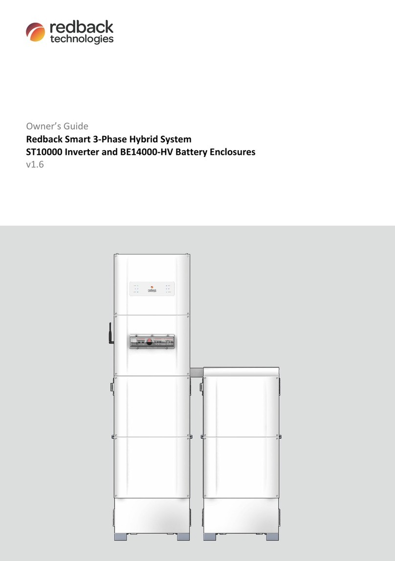
Redback SH5000 User manual

Installation Manual
Redback Smart Hybrid System
SH5000
Inverter
BE14000 Battery Enclosure
V2.0

HISTORY
VERSION
ISSUED
COMMENTS
1.0
10-Jul-20
Released for print production
1.1
05-Jul-21
Added Single Line Diagram; added Regional Setting notes; other minor edits
1.2
13-Sep-21
Updated; Re-organized; Rebranded
1.21
30-Sep-21
Spec Table Grid Interactive Port Rated Output Current AC 21.7A (was 24.5A)
1.22
19-Dec-21
Spec table updated; Firmware info added.
1.23
04-Mar-22
Wi-Fi compatibility update
1.3
11-Mar-22
Spec table updated- improved MPPT range; references to dual enclosures added.
2.0
10-May-22
P9 Added limitation due to not testing to AS/NZS 4777.2:2020 for multiple phase
combinations;
P24 Grid-side MCB info added: MCB Type C 40A; Backup CCT Sub-board RCD info added:
MCB/RCD Type A 30mA.
P29 BoS communications connection diagram redrawn; Ethernet cable assembly info
improved; DRED section reformatted.
P30 Relays section updated to match other documents.
P34 Additional instruction added "Plug Cable A into Fan Controller BATT port".
P49 Earth fault alarm information added.
P63 Reformat close-up and handover and move to inside back cover.
CONTACT INFORMATION
Phone:
1300 240 182
International phone:
+61 7 3180 2325
Address:
Building 1015, 80-120 Meiers Rd, Indooroopilly QLD 4068, Australia
Email:
customersupport@redbacktech.com
Website:
redbacktech.com
NOTICE OF COPYRIGHT
Installation
Manual Redback Smart Hybrid System ©2021 Redback Technologies.
All Rights Reserved. This work is copyright, apart from any use permitted under the Copyright Act 1968. No part may be
reproduced by any process, nor may any other exclusive right be exercised without the
permission of Redback Technologies
Limited.
PRIVACY NOTICE
Redback will use the
personal information provided to us only for warranty purposes. Without this information we will not be
able to process your warranty claim. If you require further information
about our privacy policy, please visit our website at
redbacktech.com.
340-00435-02

Redback Technologies
Installation Manual - Redback Smart Hybrid System - v2.0 3
Start here…
This manual describes the installation and commissioning of a Redback SH5000 Smart Hybrid Inverter (hereafter called the
SH5000 or the “Inverter”) and the Redback BE14000 Battery Enclosure (hereafter called the BE14000 or the “Enclosure”).
The goal is to maximise solar energy usage and minimise energy consumed from the utility.
This manual is for use by Installers and Installer Companies.
Before you go to site…
Read this manual.
The installation manual contains all the information you will need for most installation scenarios.
Book a support call
If you think you will require assistance, book Redback Technical Support 2 days before going to site. This ensures
that technical support is reserved for you if you are on-site and need assistance. Redback support is in Brisbane,
Australia and is available 8am-4pm (Brisbane time) Monday to Friday. There are three ways to book a support call:
Web: redback.link/support
SMS: +61 417 632 065
Call from Australia: 1300 240 182
Call from New Zealand: +61 7 3180 2325
Register the installation
Early registration makes it possible to do a functional, testable installation even if some information is not available
e.g., installation in a spec home where the owner’s information is not available. You can also pre-assign the
installation inspector.
Register the installation at redback.link/register (+Add device).
Need something else?
Visit the Redback Document Library
Installer and Owner documentation is available for our current products. Go to redback.link/docs
Contact the Redback Customer Support Team (Monday to Friday, 8am-4pm AEST)
In Australia: 1300 240 182
In New Zealand: +61 7 3180 2325
Email: customersupport@redbacktech.com

4Installation Manual - Redback Smart Hybrid System - v 2.0
Contents
Know your product................................................................................................................................. 7
1.1 Major components .............................................................................................................................. 7
1.2 Dimensions and weights ...................................................................................................................... 8
1.3Installation space ................................................................................................................................. 8
1.4 Compatibility and limitations............................................................................................................... 9
1.5 Backup circuit design notes ................................................................................................................. 9
Installation ........................................................................................................................................... 10
2.1 Installation overview.......................................................................................................................... 12
2.1.1 Before you go to site............................................................................................................ 12
2.1.2 At site................................................................................................................................... 13
2.2 Guide to AS5139 installation requirements for BE14000................................................................... 14
2.2.1 Installation on an exit path .................................................................................................. 14
2.2.2 Installation on a blank wall .................................................................................................. 15
2.2.3 Installation near a corner..................................................................................................... 15
2.2.4 Installation with a low ceiling............................................................................................... 16
2.2.5 Installation near a corner, with low ceiling .......................................................................... 16
2.3 Preliminary electrical installation....................................................................................................... 17
2.4 Installing the BE14000 Battery Enclosure .......................................................................................... 18
2.4.1 Overview.............................................................................................................................. 18
2.4.2 Pre-assembly........................................................................................................................ 18
2.4.3 Installation ........................................................................................................................... 19
2.5 Installing the SH5000 inverter hardware ........................................................................................... 20
2.5.1 Overview.............................................................................................................................. 20
2.5.2 Wall Mounting frame........................................................................................................... 20
2.5.3 Balance of System (BoS)....................................................................................................... 21
2.6 Inverter electrical connections .......................................................................................................... 22
2.6.1 Overview.............................................................................................................................. 22
2.6.2 Solar array connections ....................................................................................................... 23
2.6.3 Single-phase grid connection ............................................................................................... 24
2.6.4 Non-standard installation .................................................................................................... 25
2.7 Installing the Energy Meter & CTs...................................................................................................... 26
2.7.1 Overview.............................................................................................................................. 26
2.7.2 Installation notes ................................................................................................................. 26
2.7.3Meter Installation on a DIN rail............................................................................................ 26
2.7.4 One, two or three phase installations .................................................................................. 27
2.7.5 AC-coupled configuration .................................................................................................... 28
2.8 Inverter communications connections .............................................................................................. 29
2.8.1 Energy meter ....................................................................................................................... 29
2.8.2 Ethernet (recommended) .................................................................................................... 29
2.8.3 DRED .................................................................................................................................... 29

Redback Technologies
Installation Manual - Redback Smart Hybrid System - v2.0 5
2.8.4 Relays................................................................................................................................... 30
2.9 Battery enclosure connections (if fitted) ........................................................................................... 30
2.10 Installing the SH5000 Inverter ........................................................................................................... 31
2.10.1 Move BoS to final location ................................................................................................... 31
2.10.2 Install Inverter...................................................................................................................... 31
2.10.3 BoS to Inverter communications.......................................................................................... 31
2.11 Battery installation ............................................................................................................................ 32
2.11.1 Overview.............................................................................................................................. 32
2.11.2 Battery installation notes..................................................................................................... 32
2.11.3 Preparing Pylontech batteries.............................................................................................. 33
2.11.4 Position batteries in the enclosure ...................................................................................... 33
2.11.5 Battery BMS, power, and earth connections ....................................................................... 34
Commissioning ..................................................................................................................................... 35
3.1 Overview............................................................................................................................................ 35
3.2 Commission Pylontech batteries ....................................................................................................... 35
3.3 Inverter start-up ................................................................................................................................ 35
3.3.1 Inverter start-up notes......................................................................................................... 35
3.3.2 Inverter start-up procedure ................................................................................................. 35
3.4 Onboarding the inverter .................................................................................................................... 36
3.4.1 Connection notes (to homeowner’s network) ..................................................................... 36
3.4.2 Connect RedbackINSTALL to the inverter ............................................................................ 37
3.4.3 Onboarding (Connect to the local network) ........................................................................ 38
3.5 Notes on regional settings ................................................................................................................. 39
3.6 Redback product firmware version.................................................................................................... 40
3.6.1 Identify using RedbackINSTALL ............................................................................................ 40
3.6.2 Identify using the Redback Portal ........................................................................................ 40
3.7 Notes on Relay configuration............................................................................................................. 41
3.8 Compliance inspections ..................................................................................................................... 42
3.8.1 Assigning an inspector ......................................................................................................... 42
3.8.2 Compliance Inspection......................................................................................................... 43
Inverter operation ................................................................................................................................ 44
4.1 Shutdown procedure ......................................................................................................................... 44
4.2 Bypass switch operation .................................................................................................................... 44
4.3 EMS restart ........................................................................................................................................ 45
4.4 Inverter restart .................................................................................................................................. 46
4.5 Inverter operating modes .................................................................................................................. 47
4.5.1 Auto mode ........................................................................................................................... 47
4.5.2 Standby mode...................................................................................................................... 47
4.5.3 Charge battery mode ........................................................................................................... 47
4.5.4 Discharge battery mode....................................................................................................... 48
4.5.5 Backup mode ....................................................................................................................... 48
Troubleshooting ................................................................................................................................... 49
5.1 Earth fault alarm ................................................................................................................................ 49

6Installation Manual - Redback Smart Hybrid System - v 2.0
5.2 Inverter Status LEDs ........................................................................................................................... 49
5.3 EMS Status LEDs................................................................................................................................ 52
5.4 SM3000 Energy meter diagnostics..................................................................................................... 54
5.4.1 SM3000 features.................................................................................................................. 54
5.4.2 Energy meter/CT troubleshooting ....................................................................................... 54
5.5 Internet connection problems ........................................................................................................... 55
5.6 Inverter unexpected shutdown.......................................................................................................... 55
5.7 Reset Pylontech batteries .................................................................................................................. 56
Maintenance ........................................................................................................................................ 57
Specifications ....................................................................................................................................... 58
Related links and documents ................................................................................................................ 61
Close-up and handover ......................................................................................................................... 63
9.1 Close-up ............................................................................................................................................. 63
9.2 Handover ........................................................................................................................................... 63
Symbols used in this manual
SYMBOL
DEFINITION
SYMBOL
DEFINITION
LETHAL DANGER.
Risk of electrocution.
CAUTION!
Hazard to equipment
DANGER.
Risk of electrical shock.
EXPLOSION HAZARD
WARNING!
Hazard to human life
LIGHTNING STRIKE
HAZARD
WARNING! Burn hazard
SHARPS HAZARD
TIPPING HAZARD
. Do not leave unattended.
FIRE HAZARD
HEAVY LIFT
. Seek assistance.
DELAY.
Wait specified time.
INFORMATION.The information provided is important for
the correct installation, operation and or maintenance of
the equipment. Failure to follow the recommendations
could result in a warranty claim being denied.
PPE REQUIRED. Use appropriate
personal
protective equipment.
Symbols used elsewhere
SYMBOL
DEFINITION
SYMBOL
DEFINITION
HEAVY!
Bend knees to lift.
DELAY.
Wait specified time.
HEAVY!
Two-person lift required.
REFER TO DOCUMENTS.
PACKAGE MASS.
In kilograms.
Do not dispose as household waste.
THIS SIDE UP. The package must always be transported,
handled, and stored with arrows pointing up.
This product contains recyclable parts.
Dispose of correctly.
S
TACKING LIMIT.Stack packages six high or less.
FRAGILE. Handle with care.
Do not tip. Do not sling.
KEEP DRY The package/product must be protected from
excessive humidity and must be stored under cover.

Redback Technologies
Installation Manual - Redback Smart Hybrid System - v2.0 7
Know your product
1.1 Major components
#
PART NAME
1.
Wall Mounting Frame
2.
Inverter Retainer Yokes & Screws
3.
Inverter Assembly
4.
Inverter Front Cover
5.
Inverter Status Panel
6.
Inverter Balance of System
7.
BoS switchgear on DIN rail
8.
BoS Slotted Cover
9.
BoS Front Cover
10.
BoS switchgear hatch
11.
Battery Enclosure front cover- Upper
12.
Enclosure front cover- Lower
13.
Enclosure kick panel
14.
Enclosure Air Inlet
15.
Enclosure Security Clamps
16.
Battery Shelf (Removable)
17.
Battery: Pylontech US2000 or US3000.
Note:
US3000C will not work.
18.
Enclosure Isolator Cover
19.
Enclosure Extractor Fan
20.
BoS Wi-Fi antenna
21.
EMS (Energy Management System)
22.
Enclosure DC Isolator
23.
EMS Status LEDs
24.
BATTERY SYSTEM DC isolator
25.
PV ARRAY DC isolator
26.
Backup power meter
27.
Grid interactive power meter
28.
BACKUP AC isolator
29.
BYPASS switch
30.
INVERTER AC isolator
31.
Relays

Introduction
8Installation Manual - Redback Smart Hybrid System - v 2.0
1.2 Dimensions and weights
ITEM
CAPACITY
(NOMINAL)
WIDTH
(MM)
HEIGHT
(MM)
DEPTH
(MM)
SHIPPING MASS
(KG)
COMPONENT MASS
(KG)
Inverter
na
518
840
360
57
Mounting Frame:
3.5
BoS:
12.3
Inverter:
30.8
Enclosure
14.2kWh
545
1125 min
348
45
38.0
Combined
na
545
1960 min
360
-
-
PYLONTECH BATTERIES
US2000
2.4kWh
442
410
89
-
24
US3000
3.55kWh
442
420
132
-
32
Excluding batteries. Excludes Wi-Fi antenna and padlock hoops. Installed height varies slightly.
1.3 Installation space

Redback Technologies
Installation Manual - Redback Smart Hybrid System - v2.0 9
1.4 Compatibility and limitations
The Redback SH5000 is a transformer-less Inverter; all other components of
the PV system must be compatible with this type of Inverter architecture.
AC-coupled installations are possible, enabling an existing grid-tied inverter’s
output to charge a Redback controlled battery.
The Redback SH5000 Smart Hybrid Inverter and BE14000 Battery Enclosure
are not suitable for:
•Batteries not specified by Redback.
•Off-Grid installations, where there is not normally a grid
connection.
•Locations without internet access: the system can operate off-line
but should normally have internet available – Redback requires
data for warranty claims.
•Installation in full-sun locations: the inverter may overheat
resulting in reduced efficiency and or automatic shutdown.
•Exposed locations where wind driven rain may penetrate the enclosure.
•Use with generators.
•Use with 5Ghz Wi-Fi networks
Multiple inverter energy systems
•SH5000 systems have not been tested for Section 5 of AS4777.2:2020—installation of SH5000s in a multiple
inverter energy system requires they are installed & used in accordance with the requirements of AS/NZS 4777.1.
1.5 Backup circuit design notes
The SH5000 includes one backup output activated during a grid outage and powered by the system batteries (4600W max.) and
or available PV (5000W max). Loads on the backup circuit must be selected to extend the backup power availability, noting:
•Continuous battery-only power delivery up to 4600W.
•Peak power delivery of 6900W for up to 10 seconds (for high
starting currents).
•System self-protects and shuts down if power limits are exceeded.
•Output is reduced above 45°C ambient temperature.
•System shuts down if 60°C ambient is exceeded.
The backup circuit is suitable for low power or intermittent use devices such as
refrigerators; freezers; LED or florescent lighting; small kitchen appliances;
computers; radio or televisions.
High starting-current or high operating-current loads must not be connected to
the Backup circuit e.g., hot water systems; air conditioners; ovens or cooktops;
spas or saunas or pool pumps.
Backup circuit
New circuit required?
Yes No
Backup circuit
inclusions
Acceptable
Not Acceptable
Refrigerators and freezers
Critical medical devices
Small, occasional use, plug-in appliances
e.g., microwaves, kettles
Air conditioners
Ovens and stoves
TV, radio, computer, phone, router
Hot water systems
Low energy lighting & fans
Spas or saunas
Household tank water pumps
Pool pumps
WARNING. This equipment is NOT
intended for use with life support
equipment or other
medical
equipment or devices.
NOTE: This product supports
Pylontech US2000 and US3000
batteries only. Other Pylontech
and other
batteries cannot work in
this product.
WARNING. Installation in violation
of these limitations may void the
warranty (refer to the Warranty
document).
WARNING. Batteries must be
fitted i
f a backup circuit has been
connected to the inverter.
PV-only
power is not satisfactory
for
backup circuits
—backup load and
PV power are variable and
unpredictable
—when backup load
exceeds PV power the
Inverter will
automatically shut down and
restart.

Installation
10 Installation Manual - Redback Smart Hybrid System - v2.0
Installation
Important safety instructions – please read
This document contains important safety instructions for products produced by Redback Technologies. Please read all the
instructions and cautionary markings on the product and on any accessories or additional equipment included in the
installation. Failure to follow these instructions could result in severe shock or possible electrocution. Always use extreme
caution to prevent accidents.
Audience
Installation, maintenance, and connection of inverters must be performed by qualified personnel, in compliance with local
electrical standards, wiring rules and the requirements of local power authorities and/or companies (for example AS4777 and
AS/NZS 3000 in Australia). The Redback Smart Hybrid strictly conforms to all related safety rules in design and test.
Safety regulations relevant to the location should be followed during installation, operation, and maintenance. Improper
operation may cause electric shock, or damage property, inverter, or equipment.
These instructions are for use by skilled, qualified personnel who:
•Meet all local and governmental code requirements for licensing and training for the installation of electrical power
systems with AC and DC voltage up to 600 volts
•Have CEC accreditation for installing grid-connected PV systems and energy storage systems
•Have knowledge of the functional principles and operation of grid-connected systems and knowledge of the installation of
electrical devices
•Understand the risk associated with installing and using electrical devices and can implement appropriate risk
management strategies
•During the preceding 12 months, have completed Redback approved training on the installation of the Redback SH5000
Smart Hybrid Inverter and BE14000 Battery Enclosure.
General safety
SYMBOL
DEFINITION
WARNING: Limitations on use
This equipment is NOT intended for use with life support equipment or other medical equipment or devices.
CAUTION: Equipment damage
Only use components or accessories recommended or sold by Redback Technologies or its authorised agents.
IMPORTANT
. Do not attempt to install this equipment if it appears to be damaged in any way. See the Warranty
document
for instructions on returning the equipment.
Personal safety
SYMBOL
DEFINITION
WARNING: PERSONAL INJURY
•Use safe lifting techniques when handling this equipment. For guidance visit safeworkaustralia.gov.au or
contact your local WHS authority.
•Use standard safety equipment when working on this equipment such as safety glasses, ear protection,
steel-toed safety boots, safety hard hats, etc.
•Use standard safety practices when working with electrical equipment. (Remove all jewellery, use insulated
tools, wear cotton clothing etc).
•Never work alone when installing or servicing this equipment. Have an assistant to help if necessary.
•Do not touch the inverter during operation. The temperature of some parts of the inverter may exceed 60°C
during operation. Let it cool for at least 5 minutes after shutdown before touching it.
•Ensure that children, pets, and other animals are kept away from the inverter, solar arrays, battery bank and
utility grid components.
•If the equipment is used in a manner not specified by the manufacturer, the protection provided by the
equipment may be impaired.

Redback Technologies
Installation Manual - Redback Smart Hybrid System - v2.0 11
Battery safety
SYMBOL
DEFINITION
IMPORTANT
•Use the battery types recommended by Redback Technologies. Follow the battery manufacturer’s
recommendations for installation and maintenance.
Insulate batteries against freezing temperatures. Note: batteries freeze more easily when discharged.
•Remote or automatic generator control systems: disable the starting circuit and/or disconnect the generator
from its starting battery while performing maintenance.
Equipment safety
SYMBOL
DEFINITION
WARNING: LETHAL VOLTAGE
•Identify all possible sources of energy. Ensure ALL sources of power are disconnected before performing any
installation or maintenance on this equipment. Confirm that the terminals are de-energised using a validated
voltmeter (rated for a minimum 1000 VAC and 1000 VDC) to verify the de-energised condition.
•Do not perform any servicing other than that specified in the installation instructions unless qualified to do so
or have been instructed to do so by Redback Technologies technical support personnel.
•Solar arrays may be energised even in low ambient light. Install a high voltage DC rated disconnect, breaker,
or accessible fuse box to ensure a safe disconnect from the system (depending on local code requirements).
•To avoid electric shock, disconnect the DC input and AC input of the inverter at least 5 minutes before
performing any installation or maintenance.
•Completely disconnect all sources of power before proceeding with any maintenance. Do not open the upper
inverter compartment of the system.
•Do not tighten the AC and DC terminals or pull on the AC and DC wiring when the inverter is running.
WARNING:
BURN HAZARD
•External and internal parts may be hot. Do not remove the cover during operation or touch any internal parts.
Be sure to allow enough time for internal parts to cool down before attempting to perform any maintenance.
WARNING: FIRE HAZARD
•Do not keep combustible or flammable materials in the same room as the equipment. The Redback Smart
Hybrid contains relays and switches which are not ignition protected.
•Ensure AC, DC and ground cable sizes conform to local codes and are fit for purpose. See product manuals for
minimum size requirements. Ensure all conductors are in good condition. Do not operate the unit with
damaged or substandard cabling.
CAUTION: EQUIPMENT DAMAGE
•When connecting cables from the inverter to the battery terminals, ensure the proper polarity is observed.
Connecting the cables incorrectly can damage or destroy the equipment and void the product warranty.
•Thoroughly inspect the equipment prior to energising. Ensure no tools or equipment have been left behind.
•Ensure clearance requirements are strictly enforced. Keep all vents clear of obstructions that can prevent
proper air flow around, or through, the unit.
•Do not open the upper front cover of the inverter. Apart from performing work at the wiring terminals (as
instructed in this manual), touching or changing components without authorisation may cause injury to
people, damage to the inverter and annulment of the warranty.
•Static electricity may damage electronic components. Take appropriate steps to prevent such damage to the
inverter; otherwise the warranty may be annulled.
•Ensure the output voltage of the proposed solar array is lower than the maximum rated input voltage of the
inverter; otherwise the inverter may be damaged, and the warranty annulled.
•Solar modules should have an IEC61730 Class A rating.
CAUTION: LIGHTNING PROTECTION. The PV arrays in this system must be protected by a Lightning Protection
System compliant with AS/NZS5033:2014.

Installation
12 Installation Manual - Redback Smart Hybrid System - v2.0
2.1 Installation overview
2.1.1 BEFORE YOU GO TO SITE
A few simple preparations will help the installation run smoothly.
If you think you will require assistance, book a support call at redback.link/support
Register the installation at redback.link/register (+Add device)
Gather the required tools
oNormal electrician’s tools including crimping kit and Cat 5 cable tools
oElectric drill/driver with 4mm Hex bit; Phillips head screwdriver bit; drill bits suitable for drilling walls
oTape measure and spirit level
oInternet connected device with RedbackINSTALL app
Gather information required
Gather the following information for use during registration, installation, onboarding, and commissioning.
System serial number:
Your Redback Installer Login:
Apply at redback.link/apply
Homeowner
details
(required)
Full name:
Installation address:
Email:
Mobile:
Homeowner
Wi-Fi details
Wi-Fi Name:
Wi-Fi Password:
Installation configuration
Regional Safety Zone
Soft Export Limit
Hard Export Limit
Soft Generation Limit
Hard Generation Limit
Compliance Inspector
Relay Assignments
Relay 1
Relay 2
Relay 3
Relay 4
Installation by non-approved installers may void the product warranty.
Not sure?
You are approved to install Redback products if you:
•Are a Redback registered and qualified installer, and
•Hold the required qualifications for installing grid-connected inverters, and
•Have a Redback Installer login.
Contact Redback on
1300-240-182 if you are
unsure of your approval
status.

Redback Technologies
Installation Manual - Redback Smart Hybrid System - v2.0 13
2.1.2 AT SITE
Ensure Wi-Fi availability (if to be used)
Measure the home Wi-Fi strength at the proposed installation site. Review installation plan if Wi-Fi strength is less than -
70dBm, otherwise ongoing connection problems may occur.
Wi-Fi
Strength
1:
None2
Weak
(< -70dBm)3
Good
(approx. -70dBm)
Strong
(> -70dBm)
1. Test inverter location before installation
2.
Mandatory: Request Redback Customer Service to set the inverter to “Off Comms”
3. Find an installation site with Good or better Wi-Fi strength
Review the proposed inverter location.
•Does it meet the requirements of AS/NZS5139? See section 2.2.
•Is it out of direct sunlight?
•Will it be exposed to heavy rain and wind, or is there a flood risk?
•Is it a coastal environment? Will it be exposed to salt spray?
•Is the mounting wall flat (to prevent distortion) and structurally sound (to carry 47kg load)? Are spacers required?
•Is the floor surface flat? Do you need packers?
•Is there 150mm clearance all-round (for cooling) and at least 2150mm height available?
Hardware
SH5000 ONLY
INVERTER + BE14000
SH5000 + 2X BE14000
Install Wall Mounting Frame
Install BoS
Install Inverter
Install Battery Enclosure
Install Wall Mounting Frame
Install BoS
Install Inverter
Install batteries & cables
Install Battery Enclosures & Connection Kit*
Install Wall Mounting Frame
Install BoS
Install Inverter
Install batteries & cables
* Refer to redback.link/shck
Electrical
•Run and connect LV cables and conduits to the BoS from PV and main or sub-board
•Install any non-standard accessories e.g., relays or new backup circuit
•Install an energy meter and run ethernet from meter to BoS
•Run ethernet from home network router to BoS (recommended)
•Complete connections to BoS (switchboard, PV, backup circuit)
Commissioning
•Test the electrical installation
•Power ON the inverter
•Commission using RedbackINSTALL
•Fit covers and clean worksite
•Document the installation
•Handover to homeowner

Installation
14 Installation Manual - Redback Smart Hybrid System - v2.0
2.2 Guide to AS5139 installation requirements for BE14000
For AS5139:2019 compliance, the BE14000 is defined as a pre-assembled battery system. AS5139 prescribes allowable battery
system locations and fire-proofing requirements. AS5139 is referenced in AS4777.1, AS3000 and the BCA, and all new or
modified battery system installations must comply.
The installer is responsible for completing installation in accordance with all relevant standards and regulations. The key
AS5139 requirements for BE14000 installation are:
•Install the BE14000 against a wall in a clear-zone containing no windows, doors, exits, vents, or appliances not
related to the BE14000. The clear-zone extends 600mm from the sides and 900mm above the BE14000.
•Fireproof any combustible wall in the clear-zone if a habitable room exists on the opposite side of that wall. Fire-
proofing materials must comply with AS1530.1.
•Fireproof any structure e.g., ceiling or eave less than 900mm above the BE14000 to the full width of the clear-zone
and the lesser of 960mm from the wall or to the edge of the structure.
•Use fire-retardant sealant to seal all penetrations through the wall that exceed 5mm internal diameter.
•Ensure 1m clearance in front of the BE14000 if it is located on a fire exit path.
•Protect the BE14000 from vehicle impact if this is a likely occurrence- use a bollard or similar device.
The most likely installation scenarios are illustrated below: any clear zone may need to be fireproofed> Note: the second
enclosure is optional.
2.2.1 INSTALLATION ON AN EXIT PATH

Redback Technologies
Installation Manual - Redback Smart Hybrid System - v2.0 15
2.2.2 INSTALLATION ON A BLANK WALL
2.2.3 INSTALLATION NEAR A CORNER

Installation
16 Installation Manual - Redback Smart Hybrid System - v2.0
2.2.4 INSTALLATION WITH A LOW CEILING
2.2.5 INSTALLATION NEAR A CORNER, WITH LOW CEILING

Redback Technologies
Installation Manual - Redback Smart Hybrid System - v2.0 17
2.3 Preliminary electrical installation
The Inverter and Balance of System (BoS) are hung on the Wall Mounting Frame.
When hung, the BoS and Inverter restrict access to the internal conduit space.
It may be faster (but not essential) to run cables and conduits before hanging
the BoS or inverter. Ensure that the cable tails have generous bend radii, are
long enough to reach the BoS and form effective drip loops.
The Wall Mounting Frame has numerous pass-throughs to accommodate rigid or
flexible conduit up to
φ
25mm. Do not use the lower pass-throughs as this will
affect future battery enclosure installation. Typical conduit routing is shown at
right.
Cables that can be run in advance include:
•Solar array output
•Grid connection to main or sub-board, using 2-core + earth (Flat,
TPS-cable or Orange Circular cable preferred)
•Cable to Backup Circuit isolator (2-core + earth)
•Communications cable (to energy meter)
•Ethernet cable (to home network router)
All connections between inverter, BoS and batteries are internal, using supplied
cables.
# PART NAME
1.
Wall Mounting Frame
2.
Inverter Front Cover
3.
BoS Front Cover
4.
Cables
5.
Conduits

Installation
18 Installation Manual - Redback Smart Hybrid System - v2.0
2.4 Installing the BE14000 Battery Enclosure
If you are installing an inverter-only system, go to section 2.5.
WARNING TIPPING HAZARD. Keep children and animals out of the worksite. Do not leave the enclosure
unattended during installation. Fasten enclosure to the wall as soon as practical.
2.4.1 OVERVIEW
The BE14000 Battery Enclosure is designed for AS5139 compliant Redback SH5000 Smart Hybrid Inverters. The enclosure is not
designed for older or non-Redback inverters.
The enclosure can house up to four Pylontech batteries.
The installation process is:
•Review the Packing List. Verify all parts have been supplied.
•Remove front covers.
•Remove battery shelf and cross braces (optional).
•Fit padlock hoops.
•Position and install the enclosure.
2.4.2 PRE-ASSEMBLY
Open the BE14000 carton and locate the packing
list. Verify all parts are supplied.
Remove the cabinet from the transport carton.
Place on a protective surface, front-side up.
Remove the upper and lower front covers and set
aside. The covers are retained using 4mm hex-
drive screws. Take care not to damage the internal
seal.
If batteries are to be fitted, remove the kick panel.
The kick panel is hinged at the bottom edge and
secured at the top corners – remove the screws,
tilt the panel forward and slide it off the hinge
pins. Take care not to damage the internal seal.
Remove the upper shelf.
Attach the 700mm earth bonding cable to the top
of the enclosure using a M5x10 screw, and spring
and flat washers, as shown.
Attach the two padlock hoops using two M4x10
countersunk screws.

Redback Technologies
Installation Manual - Redback Smart Hybrid System - v2.0 19
2.4.3 INSTALLATION
Installation notes
•The BE14000 Battery Enclosure is pre-wired for use with an AS5139 compliant SH5000 inverter.
•Reduce heat load by installing out of full sun: ideally, the installation will be against a south facing external wall, and
under eaves.
•Ensure the location is not flood prone from water across ground, nearby downpipes, or guttering.
•Stand the enclosure on a stable, level surface. Use packers under feet if required.
•Fasten the enclosure to a flat, structurally sound wall. Waterproofing will be affected if the enclosure is twisted or
damaged. Use spacers if required.
•The enclosure features fan-assisted cooling. Ensure 150mm clear space either side. Do not block the cooling intakes
or exhaust vents.
•Ensure at least 1000mm clear height is available above the enclosure (for inverter fitting).
Installation process
Place the enclosure in the required location: on the
floor; against the wall; 150mm clear space both sides.
Set the enclosure level. Use a spirit level as required.
Add packers under feet if necessary.
Check that the wall is flat. Use spacers as required to
ensure the enclosure does not distort when fastened to
the wall.
Six mounting points are provided, as shown at right.
Fix the enclosure to the wall using suitable fasteners.
Seal around the fasteners using the supplied sealant.
Preliminary installation is complete.

Installation
20 Installation Manual - Redback Smart Hybrid System - v2.0
2.5 Installing the SH5000 inverter hardware
2.5.1 OVERVIEW
The installation process is:
•Review the Packing List. Verify all parts have been supplied.
•Install the Wall Mounting Frame.
•Install BoS hardware.
•Install associated hardware.
2.5.2 WALL MOUNTING FRAME
WARNING: STRUCTURAL REQUIREMENTS!
The wall and fasteners should be suitable to secure the hung weight of the system. Please ensure that the
selected wall is made from a suitable material (e.g. solid brick) and you use at least the recommend number of
fasteners.
Installation notes
•Install the Wall Mounting Frame correctly -
observe “TOP” markings.
•The inverter is convection cooled: provide 150mm
clearance to top and sides to ensure airflow.
•If a BE14000 is in place, stand the frame on top of
the BE14000, and fix in position.
•Otherwise, install the frame at 1125mm above the
finished floor line (FFL): this enables easy
retrofitting of BE14000 enclosure.
Fasten the Frame to the wall.
The Wall Mounting Frame is secured by eight
fasteners at any of 16 points. Choose fastener
locations that will spread loads to the structural
part of the wall.
Use the frame as a template for fasteners.
Fix the enclosure to the wall using eight (8)
suitable fasteners.
Check the frame is level (use a spirit level). Tighten
the fasteners.
Other manuals for SH5000
1
This manual suits for next models
1
Table of contents
Other Redback Inverter manuals