Redback SI5000 User manual

Owner’s Manual
Redback Smart Inverter
SI5000-6000-8000-10000
v1.4

HISTORY
VERSION
ISSUED
COMMENTS
1.0
07-Jan-22
First edition
1.1
28-Feb-23
P5 Update Owner’s contact process to raise case via portal; P6 Update Inverter Internet
settings flow; P16, 17 Add Interlocked inverters behaviour under fault; P17 Add Earth fault
information; P21 Add Maximum PV Input Power; P21 Correct Maximum Back Feed Current
(was Feedback).
1.2
08-May-23
P6 Add Smart Load Control to System Overview diagram.
P6, 11, 12 Add “RCD Type A 100mA” to diagrams.
P7 Add Smart Load Control to FAB table.
P10 Add “Use Smart Load Control”.
1.3
23-May-23
P18 Removed 4G mentions.
1.4
10-Jul-23
P21 Update specifications: I
MP
; I
SC
; MPPT Operating Voltage (Range).
CONTACT INFORMATION
Phone:
1300 240 182
International phone:
+61 7 3180 2325
Address:
Building 1015, 80-120 Meiers Rd, Indooroopilly QLD 4068, Australia
Email:
customersupport@redbacktech.com
Website:
redbacktech.com
NOTICE OF COPYRIGHT
O
wner’s Guide Redback Smart Inverter SI5000-6000-8000-10000 ©2023 Redback Technologies.
All Rights Reserved. This work is copyright, apart from any use permitted under the
Copyright Act 1968. No part may be
reproduced by any process, nor may any other exclusive right be exercised without the permission of Redback Technologies
Limited.
PRIVACY NOTICE
Redback will use the
personal information provided to us only for warranty purposes. Without this information we will not be
able to process your warranty claim. If you require further information about our privacy policy, please visit our website at
redbacktech.com.

Redback Technologies
Owner’s Guide – Redback Smart Inverter - v1.4 3
Contents
Welcome.................................................................................................................................................5
Introduction ............................................................................................................................................5
Getting help ............................................................................................................................................5
Other resources.......................................................................................................................................5
Transfer of ownership .............................................................................................................................5
System overview .....................................................................................................................................6
Know your product..................................................................................................................................7
Features and benefits of your Redback system ....................................................................................7
System limitations ................................................................................................................................7
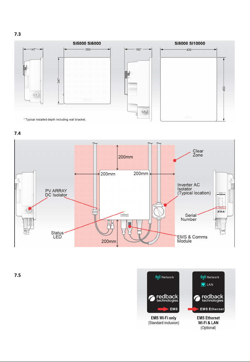
Product dimensions ..............................................................................................................................8
Typical installation ................................................................................................................................8
EMS module nameplates ......................................................................................................................8
Getting the best from your system...........................................................................................................9
Keep your system in good condition.....................................................................................................9
Use Smart Load Control (optional hardware is needed) .....................................................................10
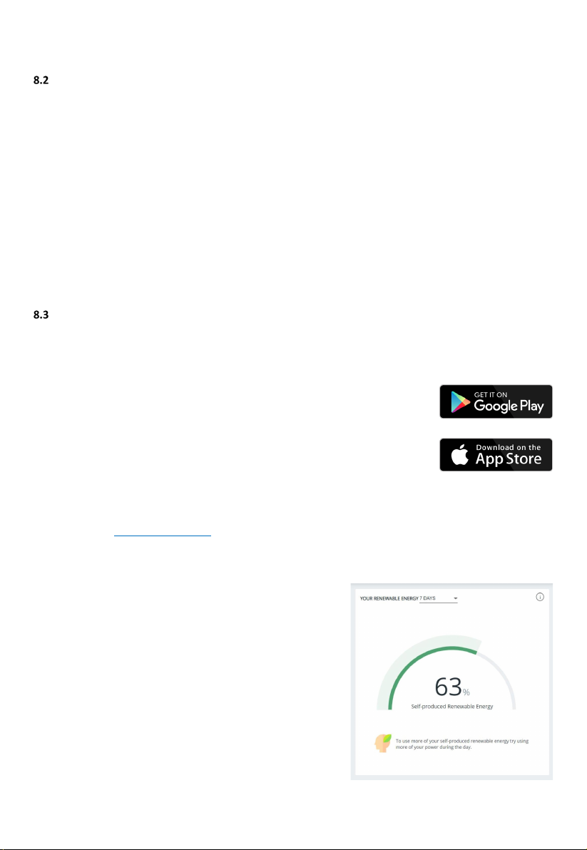
Monitor performance .........................................................................................................................10
8.3.1 MYRedback app ....................................................................................................................10
8.3.2 Redback portal ......................................................................................................................10
Inverter operation .................................................................................................................................11
Shutdown procedure ..........................................................................................................................11
Restart procedure ...............................................................................................................................12
Connect your system to the internet......................................................................................................13
Ethernet..............................................................................................................................................13
Bluetooth ............................................................................................................................................14
Troubleshooting ....................................................................................................................................15
Most frequent symptoms ...................................................................................................................15
Inverter unexpectedly or frequently shutting down ...........................................................................16
Multiple inverter installations.............................................................................................................16
Internet connection problems ............................................................................................................16

4Owner’s Guide – Redback Smart Inverter – v1.4
Inverter Status LEDs............................................................................................................................17
11.5.1 Inverter Status LED ...............................................................................................................17
11.5.2 Inverter status LED (multiple-inverter installations) .............................................................17
11.5.3 Comms module LEDs ............................................................................................................18
PA110 Smart Meter diagnostics..........................................................................................................19
Maintenance schedule...........................................................................................................................20
Specifications ........................................................................................................................................21
Redback installation details ...................................................................................................................23
Installer’s checklist ................................................................................................................................23

Redback Technologies
Owner’s Guide – Redback Smart Inverter - v1.4 5
Welcome
Congratulations on the purchase of your new Redback Smart Inverter. Our products are designed and manufactured to our
high-quality standards and will provide years of service.
This manual describes the features, use and maintenance of your Smart Inverter.
Introduction
Your Redback Smart Inverter converts solar energy from rooftop PV to electricity, which can power your home and or be
exported to the grid, when permitted*.
Following installation and setup by the installer, your inverter works quietly in the background. Apart from occasional
maintenance, your inverter is set-and-forget, but you can stay involved if you wish.
The MyRedback app and the Redback portal provide a comprehensive view of the energy consumed by your home, including
when you consume it. You can use this information to optimize your energy usage patterns and improve your usage of
self-generated power.
*The electricity network operator in your area may limit the power you can export to the network, or the times at which it may
be exported. Ask your installer or electricity retailer if any export restrictions apply to your location.
Getting help
Contact your installer first. You can usually find their contacts details on the inverter, inside the meter box, or inside the back
cover of this booklet. If your installer is unable to assist, try one of the other resources below or open a case with our Customer
Support Team at https://portal.redbacktech.com/supportrequest.
Other resources
SOURCE
COMMENT
LINK
Owner’s guide
This document in pdf format
redback.link/siog
Redback Document Library
Password required
redback.link/docs
Transfer of ownership
If a Redback system is already installed in your new home, welcome to the Redback family. To get the best from your Redback
system, and to receive important notifications from your system, you need to setup an account using a valid email address. You
can then access the system using the Redback app or portal, see how the system is working for you, and gain insights to help
maximise your consumption of self-generated energy.
When we setup your account, we’ll also arrange for remaining warranty to be transferred to your name and we can answer any
questions you may have about your system.
To get started, initiate a case with the Redback Customer Support Team at https://portal.redbacktech.com/supportrequest.
We’ll get back to you as soon as possible. We’ll need some proof of ownership too, so be ready for that.

Introduction
6Owner’s Guide – Redback Smart Inverter – v1.4
Important safety instructions – please read
This document contains important safety instructions for products produced by Redback Technologies. Please read all the
instructions and cautionary markings on the product and on any accessories or additional equipment included in the
installation. Failure to follow these instructions could result in severe shock or possible electrocution. Always use extreme
caution to prevent accidents.
SYMBOL
DEFINITION
WARNING: LETHAL VOLTAGE INSIDE
Do not remove
any system cover unless qualified to do so.
Do not perform any servicing other than that specified in the maintenance instructions.
DANGER.
Risk of electrical shock. Proceed with caution.
WARNING: Burn Hazard.
External and internal parts may be hot. Do not remove covers during operation or touch any internal parts.
The
temperature of some parts may exceed 60°C during
operation. After shutdown, allow the inverter to cool for at
least 5 minutes before touching.
CAUTION: Hazard to Equipment
Only use components or accessories recommended or sold by Redback Technologies or its authorised agents.
Handle all parts
with care and follow instructions provided.
WARNING: Fire hazard
Do not keep combustible or flammable materials in the same room as the equipment. The Redback Smart
Inverter
contains relays and switches that are not ignition protected.
Ensure clearance
requirements are strictly enforced: Maintain 200mm of clear space around unit to ensure
unobstructed airflow
for convection cooling.
DELAY.
Wait specified time e.g., 10 minutes.
This symbol indicates the information provided is important for the
correct operation and or maintenance of the
equipment. Failure to follow the recommendations may result in annulment of the product warranty.
System overview

Redback Technologies
Owner’s Guide – Redback Smart Inverter - v1.4 7
Know your product
Features and benefits of your Redback system
SYSTEM FEATURE
BENEFIT
REQUIREMENT
Internet connected
System monitoring and management using the
MyRedback app or the Redback portal.
Remote viewing of system status.
Permanent internet connection
using your
Wi-Fi or ethernet based
home network
.
MyRedback app and the
Redback portal
See your true usage patterns to find ways to increase
your self-consumption and reduce your electricity bill.
Share system access with family, tenants etc
All-in-one design
Neat appearance; Easy to keep clean.
Simple interface
Two or three LEDS notify system status and aid
diagnostics.
Integrated PV Isolator
Discrete, but easy to access and use if the solar panels
need to be isolated.
EMS
The Redback Energy Management System (EMS) is the
system’s internal controller.
Internet connection for occasional
software updates.
Smart Load Control
(optional)
Operate your large loads (e.g., pool pump or hot water
system) to maximise your solar consumption
Suitable large load relay installed
and configured.
Low maintenance
Owner can complete essential annual maintenance.
Service person is not usually needed.
Basic cleaning skills.
Grid power quality
monitoring
System can self-protect from poor quality grid power
and recover when quality improves.
Automatic grid disconnects
during a power outage
For safety, the system automatically disconnects from
the grid during a power outage to prevent PV being
exported to the network.
Internal overload protection
The system will self-protect if it detects excessive heat
or excessive internal currents.
Critical setting protection
Critical system settings may only be changed by
electrically qualified personnel.
Ground fault and insulation
monitoring
Electrical safety for all parts of your system.
System limitations
Your Smart Inverter will not operate during a power outage:
•If your inverter detects a grid power outage (a blackout) it
automatically disconnects from the grid and deactivates itself. This
is to protect from unexpected discharge into the grid which would
pose a hazard to service personnel.
•During a blackout, PV is not available for household consumption.
•Your inverter will automatically restart when grid power is restored.
Your system is not suitable for:
•Off-Grid installations (where the grid is intentionally disconnected).
•Locations without internet access: the system can work off-line, but you will be unable to review consumption or
performance; or make informed decisions about system settings or consumption patterns. Warranty support will also
be affected.
•Prediction of your energy bills. The Redback meter is a Class 1 meter: it provides a good indication of energy
consumption; however, readings may vary slightly from the Network meters used for billing.
•Use with generators.
WARNING! This equipment is
NOT intended for use with life
support equipment or other
medical equipment or devices.

Introduction
8Owner’s Guide – Redback Smart Inverter – v1.4
Product dimensions
Typical installation
EMS module nameplates
Your inverter includes a Communications Module located at the
bottom centre of the inverter. Modules are specified/optioned
according to needs. The nameplate identifies the type of module
fitted.

Redback Technologies
Owner’s Guide – Redback Smart Inverter - v1.4 9
Getting the best from your system
Your Redback system is designed to operate autonomously – the level of interaction is up to you.
A set-and-forget approach will work fine: occasional maintenance is all that is required.
Alternatively, you can dive into your data and make informed decisions to optimize your system and lifestyle to maximize the
return on your investment.
Either way, the first step is to look after your Redback.
Keep your system in good condition
Keeping your system in good condition maintains efficiency, increases longevity, and helps us help you, if the need arises. There
are three key items requiring your attention.
Cooling
Your system uses fresh air to cool the inverter. If your system becomes too
hot its efficiency decreases, and it may even shut down.
There must always be 200mm of clear space adjacent, above, and below
your system. Ensure no items are left near the base of the system or placed
on top of the inverter, as air flow will be obstructed.
The system must not be enclosed i.e., do not build a cabinet around it.
Maintenance
Complete the annual maintenance items in Section 12. In very dusty
conditions you may need to clean the filters more frequently.
Internet connection
Data is required to get the best out of your system. A permanent internet
connection enables the system to send data to the Redback cloud, where
the MyRedback app and Redback portal present helpful information,
enabling you to see your system’s performance. Your installer or Redback
can also use the data to diagnose problems or suggest improvements,
based on your actual usage.
Note: Your system will continue to function without an internet connection,
but you will be unable to receive any fault notifications; no data will exist
for the period of disconnection; software updates will not occur; and
remote support will be limited. You may also affect your warranty coverage
if the system is offline.

Operation
10 Owner’s Guide – Redback Smart Inverter – v1.4
Use Smart Load Control (optional hardware is needed)
Redback’s Smart Load Control feature enables you to make the best of your generated energy by only running your large loads
(such as a pool pump or hot water system) when there is excess solar energy available.
Smart Load Control is a sophisticated system that aims to:
•Run the load using only excess PV energy.
•Avoid switching the load excessively (e.g., when a small cloud passes in front of the sun).
•Optionally, the system will ensure that the load runs for a nominated number of hours each day. This is useful for
equipment like pool pumps or hot water systems which require a minimum daily run-time.
The Smart Load Control feature is available for compatible Redback SI-series Smart Inverters and requires that a relay is
connected and controlled by the existing SI inverter energy meter. The relay switches the large load on and off.
The Smart Load Control can be over-ridden using Portal ON/OFF or scheduling commands or bypassed completely using an
optional hardware switch.
Contact your installer to install or configure Smart Load Control and associated hardware that suits your needs.
Monitor performance
Redback offers two choices for monitoring the energy performance of your household.
8.3.1 MYREDBACK APP
MyRedback provides a simple, up-to-date view of what’s happening at your place – it’s great for
quickly checking the energy flow at home. MyRedback is available for Android 7 or higher and iOS
12.1 or higher. Use the app to:
•Check your home energy usage.
•Reconnect your system to the internet.
•Review your system settings- but you’ll need to contact your installer if changes are
required.
8.3.2 REDBACK PORTAL
The Redback portal portal.redbacktech.com offers all the features of the MyRedback app plus a comprehensive history of your
system’s performance, much greater detail about your system, and direct access to support documents.
DASHBOARD
The dashboard view provides an overview of your system:
•Energy consumption trends
•Power demand
•Power being bought or exported
If nothing else, you should view the Renewable Energy Meter regularly; it
shows the system’s impact on your energy consumption during the past 7,
30 or 90 days. If it falls below 60%, it is worth reviewing your usage habits
or your system size and settings.

Redback Technologies
Owner’s Guide – Redback Smart Inverter - v1.4 11
Inverter operation
Shutdown procedure
Occasionally, it may be necessary to shut down the inverter interrupting all inverter functions.

Operation
12 Owner’s Guide – Redback Smart Inverter – v1.4
Restart procedure
Restart your inverter as shown below.

Redback Technologies
Owner’s Guide – Redback Smart Inverter - v1.4 13
Connect your system to the internet
Onboarding connects your system to the internet using your network. Connection to the network is by Ethernet cable or Wi-Fi.
There are two easy ways to check if your system is online:
1. Login to the Redback portal. If your system is “Online” and refreshing data every 6o seconds, then it is connected.
2. Login to the MyRedback app. If data is refreshing every 60 seconds, then the system is connected.
Occasionally, it may be necessary to reconnect your inverter to the internet. This most frequently occurs after a significant
disruption to your network such as replacing your router, changing passwords, or changing internet providers.
There are two onboarding processes: Ethernet or Bluetooth Low Energy (BT or BLE).
Ethernet
Ethernet is the preferred method of connection: onboarding occurs automatically, confirmed by:
•Inverter Status LED is BLUE
•Communications module LAN icon is blue.
To connect using ethernet, your system must have the optional “EMS Ethernet” communications module installed. Ask your
installer for assistance if you would like to connect using ethernet.

Operation
14 Owner’s Guide – Redback Smart Inverter – v1.4
Bluetooth
BLE onboarding is required if ethernet is not available–a Bluetooth connection is established between the inverter and the
MyRedback app, and the app will guide you through the process of connecting the inverter to your Wi-Fi network.
To onboard using Bluetooth:
1. Go to your inverter. Ensure your home network signal is Good or better at this location.
2. Shutdown and restart your system, as described in sections 9.1 and 9.2.
3. Wait for the status LED to begin flashing continuously, indicating Bluetooth is advertising.
4. On your device, open MyRedback and login. Touch the Hamburger to display the flyout menu.
5. Select Network Connection. Note your system status and select Change Network.
6. You may be notified to start Bluetooth—follow the on-screen instructions, otherwise touch Bluetooth LED Flashing
to continue.
7. Select your Wi-Fi network from the list.
8. Enter Password if asked, and touch Connect. A success message will appear.
9. Wait two minutes, then confirm onboarding success:
On the MyRedback app, check that data is refreshing every 20 seconds;
On the Portal, check that your system is online, and refreshing every 60 seconds.
10. If onboarding fails, try again, or contact Redback Customer Support for help.

Redback Technologies
Owner’s Guide – Redback Smart Inverter - v1.4 15
Troubleshooting
Most frequent symptoms
SYMPTOM
PROBABLE CAUSE
SOLUTION
No LEDs are illuminated
Local blackout
Contact your energy supplier for help.
No Grid Power to
inverter
Near inverter, turn INVERTER AC isolator ON.
At main switchboard, turn SOLAR SUPPLY MAIN Switch ON.
No Solar Generation
At the inverter, turn the PV ARRAY DC isolator ON.
No solar generation
No Grid Power
As above.
PV turned is OFF
At the inverter, turn the PV ARRAY DC isolator ON.
Insufficient sunlight
Wait for daytime weather to improve.
Lower solar generation
than expected
PV Shading
Observe your panels throughout the day, and at different times of
the year to see if shading is occurring. Over time, your panels may
become partly shaded due to nearby trees or buildings.
Dirty PV Panels
Arrange for your PV Panels to be inspected and cleaned
Inverter overheating
On the Redback portal charts,
check Inverter-Temperature.
Output is reduced if internal
temperature exceeds 45°C.
Follow the suggestions below.
Inverter overheating
Note: your inverter is
passively cooled and relies on
a temperature difference
between the inverter casing
and ambient air. Air flow
obstructions, or anything that
reduces the temperature
differential also reduces the
inverter’s self-cooling
efficiency.
Insufficient cooling
Is there 200mm clear space on
all sides of the inverter?
Ensure 200mm on all sides of
the inverter is free of
obstructions.
Are the cooling fins at the back
of the unit obstructed by dust,
insects, or other debris?
Clean the fins using a suitable
brush e.g., a Bottle Brush.
Very hot day
Wait for the temperature to
drop.
If in full or part sun, shading the
inverter may help. Contact your
installer for advice.
Ambient temperature
is high
Is the inverter affected by
nearby A/C outdoor units or
other heat sources?
Contact your installer to discuss
options.
Is the inverter in a closed room
or shed?
Ventilate or cool the room to
reduce ambient temperature.
External heat load is
excessive
Is the inverter in a full sun
location, or are there other heat
sources e.g., reflected heat, or
mounted on a metal wall?
Reduce the external heat load.
Contact your installer to discuss
options
Inverter operating
abnormally
Unknown
Shutdown inverter as described in section 9.1.
Wait 10 minutes then restart the inverter as in section 9.2
Contact your installer if inverter still does not operate correctly.
Red Inverter Status LED
Error state exists
Contact your installer.
Purple Flashing EMS
Network LED
Error state exists
Contact your installer.

Troubleshooting
16 Owner’s Guide – Redback Smart Inverter – v1.4
Inverter unexpectedly or frequently shutting down
The inverter may shut down or isolate itself from the grid if it detects supply conditions that may cause damage to the inverter;
or create an unsafe situation. Incident causes can be diagnosed by examining the data available on the portal. Unexpected
shutdowns may occur in the following circumstances:
CAUSE
RELEVANT CHARTS FOR
DIAGNOSIS (IN PORTAL) *
COMMENT
A grid outage (blackout) is occurring
Grid-Status
Wait for the grid to be restored. Your system will restart
automatically.
Grid supply is not of acceptable
quality, as defined by AS/NZS 4777.2.
Grid-Voltage
Grid
-Frequency
Grid
-Status
Ask your installer or electricity provider to investigate if
grid supply is
often poor.
If internal temperature is greater than
60
°C.
Inverter- Temperature
Battery Cabinet
-Temp.
Output is reduced above 45°C.
*You may not have access to all chart parameters. Contact your installer or Redback if you require access.
Multiple inverter installations
Your installation may include 1-3 SI-series inverters, usually connected to different phases, and these inverters operate
independently except in one situation: if any inverter encounters a fault and needs to shut down, then the other two inverters
will also shut down immediately. When the first inverter recovers, or is isolated from PV and the Grid, the other two inverters
will restart.
Internet connection problems
Occasionally, your inverter may lose internet connection and be reported as “offline”. Ethernet connected systems usually self-
repair after a system restarts. Wi-Fi problems usually require that the system is re-onboarded. The most common causes of
“offline” reports are:
INDICATION
CONNECTION AFFECTED
REMEDY
ETHERNET
WI-FI
Change of Internet Service Provider e.g., Telstra,
Optus, TPG, Dodo etc
Ethernet: Restart the system.
Wi-Fi: Restart the system and re-onboard.
New router or modem
Change of Network name or SSID
Changed settings in router or modem
Changed Wi-Fi or Network password
Wi-Fi: Restart and re-onboard
Too many users or devices on your home Wi-Fi
network
Limit users or devices; upgrade Wi-Fi router;
connect inverter using ethernet.
Wi-Fi signal is weak or variable due to obstructions
or distance between the inverter and your Wi-Fi
router’s antenna.
Experiment with Wi-Fi router locations; use a
Wi-Fi extender; connect using ethernet.

Redback Technologies
Owner’s Guide – Redback Smart Inverter - v1.4 17
Inverter Status LEDs
The Inverter is equipped with a status LED on the front panel, and a Network status LED on the communications module. The
optional EMS Ethernet module also has an Ethernet status LED. The table below lists LED indications, probable cause, and
rectification steps.
11.5.1 INVERTER STATUS LED
LED
COLOUR & PATTERN
MEANING
SOLUTION(S)
Green ON
Inverter is operating
normally.
OK. No action required.
Yellow ON
Inverter in Night Mode.
OK. No action needed. Night mode is
de-activated automatically.
Preparing to connect to grid
OK. Self-testing in progress. No
action needed.
Green Flashing
Inverter is starting up.
Wait for start up to complete (about
one minute).
Blue Flashing
Inverter is advertising BLE
Use Redback Install app to connect
to the inverter.
Network communications
lost.
Use Redback Install app to
reconnect to the inverter.
Blue ON
Inverter is connected to
Redback Install by BLE
Use Redback Install app to complete
setup
Red ON
A fault exists.
Restart system. If fault persists,
contact Redback.
Earth Fault Exists
Emails sent to Redback customer
service team, the registered
installer, and the system owner.
Installer to investigate.
Email is also sent when the alarm is
cleared.
Disconnected from grid due
to interlocked inverter fault.
Deal with faulted inverter. See
section 10.5.2 below.
OFF
Grid failure
Wait for power to be restored
No Power to Inverter
Enable Grid Supply to Inverter
Internal failure
Contact Redback
11.5.2 INVERTER STATUS LED (MULTIPLE-INVERTER INSTALLATIONS)
Your system may include multiple SI series inverters. The inverters are interlocked to ensure a fault on any inverter causes the
other inverters to shut down until the triggering fault is rectified, or the faulting inverter is completely powered off. Outside of
a fault event, each inverter will run independently.
LED
COLOUR & PATTERN
MEANING
SOLUTION(S)
One inverter
Other
Inverters
Unknown fault on one
inverter and grid-disconnect
on other inverters
Restart the faulting inverter. If it
restarts the other inverters will
automatically reconnect to the grid.
If the faulting inverter does not
restart, completely isolate the
inverter (PV ARRAY DC isolator OFF
and Grid AC isolator OFF). The other
inverters will reconnect to the grid.

Troubleshooting
18 Owner’s Guide – Redback Smart Inverter – v1.4
11.5.3 COMMS MODULE LEDS
INDICATION
COLOUR & PATTERN
MEANING
SOLUTION(S)
Note: LAN icon is found only
on the optional EMS
Ethernet module (illustrated)
Blue flashing
Advertising BLE
Use Redback Install app to connect
to the inverter.
Blue ON
BLE Connected
Use Redback Install app to complete
setup
Green ON
Connected to Cloud via
Wi-Fi or Ethernet
OK. No action needed.
Red ON
No connection to cloud
Wi-Fi: Complete onboarding
Ethernet: Check connection to local
network.
Purple Flashing
Error state exists.
Contact Redback
White ON
Physical ethernet
connection to a local
network.
No action needed. Ethernet
connection to LAN is automatic
when available.
OFF
No ethernet connected
Connect if needed.
BOTH OFF
No Power to inverter
Enable Grid Supply to Inverter
No power to module
Check module is correctly installed
Module faulty
Contact Redback

Redback Technologies
Owner’s Guide – Redback Smart Inverter - v1.4 19
PA110 Smart Meter diagnostics
The Redback PA110 Energy Meter is usually located at the main switchboard. It detects grid energy traffic and sends
information to the Smart Inverter. This information informs inverter operation.
To function correctly, your system requires a working PA110. Contact your installer immediately if you suspect the PA110 is not
working correctly.
LED
COLOUR & PATTERN
MEANING
SOLUTION(S)
OFF
No power to PA
During a blackout, this is normal.
If the Grid is active and the house
Main Switch is ON contact your
installer.
Flashing
Device is communicating
with the inverter.
OK. No action needed.
ON Continuosly
Communications failure
Contact your installer.

Maintenance
20 Owner’s Guide – Redback Smart Inverter – v1.4
Maintenance schedule
WARNING: ELECTROCUTION HAZARD. Lethal voltages may be present. There are no user serviceable parts
inside. Do not remove front covers.
Your Redback Smart Inverter is a low maintenance product. You should undertake the minor annual maintenance listed below.
Internal maintenance must be conducted by a qualified person, such as your installer.
Note: Heatsink fins may require more frequent cleaning in dusty conditions.
ITEM
NAME
REASON
PROCEDURE
BY SERVICE
PERSON
BY OWNER
1
Heatsink fins.
Cooling efficiency reduces
when dust, dirt or debris
accumulate on the heatsink.
Clean the heatsink fins using a
small brush e.g., a bottle brush.
2
Enclosure
Enclosure may become soiled.
Wipe down the outside of the
enclosure with a just-damp
cloth. Immediately wipe dry with
a microfibre cloth.
Do not use cleaning agents as
they may damage the finish.
3
Isolators
Ensures Isolators stay
operable
Shut down and restart the
inverter as described in sections
9.1 and 9.2.
This manual suits for next models
3
Table of contents
Other Redback Inverter manuals
Popular Inverter manuals by other brands

Victron energy
Victron energy SUN manual

Solectria Renewables
Solectria Renewables PVI 2500 Installation and operation manual

Generac Power Systems
Generac Power Systems 0784-1 owner's manual

Samlexpower
Samlexpower PST-60S-48E owner's manual

UTL
UTL GAMMA+ User's operating manual

Malekko
Malekko QUAD GATE DELAY manual