Redback ST10000 User manual

Owner’s Guide
Redback Smart 3-Phase Hybrid System
ST10000 Inverter and BE14000-HV Battery Enclosures
v1.6

History
Version
Issued
Comments
1.1 28-Apr-20 First publication
1.2 07-Jul-21 Minor edits
1.3 09-Sep-21 Rebrand
1.4 17-Nov-21 Update specification table
1.5 17-Nov-21 Update spec. table; Added ownership transfer guide.
1.6 04-Mar-22 Wi-Fi compatibility update
Contact Information
Phone:
1300 240 182
International phone:
+61 7
3180 2325
Address:
Building 1015, 80
-120 Meiers Rd, Indooroopilly QLD 4068, Australia
Email:
customer
support@redbacktech.com
Website:
redbacktech.com
Notice of copyright
O
wner’s Guide Redback Smart 3-Phase Hybrid System ST10000 Inverter and BE14000-HV Battery Enclosures ©2021 Redback
Technologies.
All Rights Reserved. This work is copyright, apart from any use permitted under the Copyright Act 1968. No part may be
reproduced by any process, nor may any other exclusive right be exercised witho
ut the permission of Redback Technologies
Limited.
Privacy notice
Redback will use the
personal information provided to us only for warranty purposes. Without this information we will not be
able to process your warranty claim. If you require further info
rmation about our privacy policy, please visit our website at
redbacktech.com.
340
-00366-03

Redback Technologies
Owner’s Guide – Redback ST10000 and BE14000-HV - v1.6 3
Contents
Welcome.................................................................................................................................................5
Introduction ............................................................................................................................................5
Features and benefits of your Redback system.........................................................................................7
Know your product..................................................................................................................................8
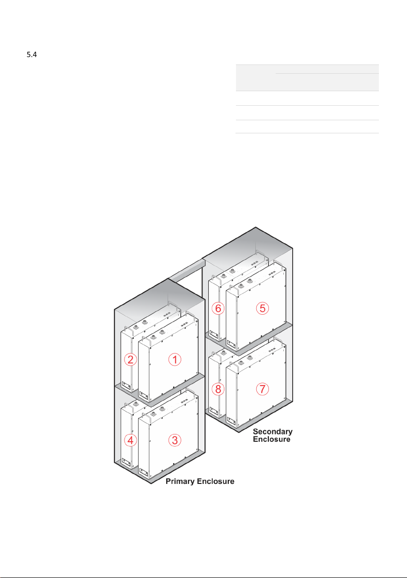
Major components and dimensions .....................................................................................................8
Status Panel LEDS..................................................................................................................................9
BoS switchgear......................................................................................................................................9
Batteries .............................................................................................................................................10
Backup circuit (optional) .....................................................................................................................11
System limitations .................................................................................................................................11
Getting the best from your system.........................................................................................................12
Keep your system in good condition...................................................................................................12
Monitor performance .........................................................................................................................13
6.2.1 MYRedback app ....................................................................................................................13
6.2.2 Redback portal ......................................................................................................................13
Getting the best from your batteries ..................................................................................................14
Getting the best from your relays.......................................................................................................14
Getting the best from your backup circuit ..........................................................................................15
Inverter operation .................................................................................................................................16
Locking up the batteries .....................................................................................................................16
EMS restart .........................................................................................................................................16
Inverter – Changing bypass modes .....................................................................................................16
Shutdown procedure ..........................................................................................................................17
Start procedure...................................................................................................................................18
Inverter operating modes ...................................................................................................................19
Auto mode ..........................................................................................................................................19
Standby mode.....................................................................................................................................19
Charge battery mode ..........................................................................................................................19
Discharge battery mode......................................................................................................................20
Backup mode ......................................................................................................................................20
Onboarding the inverter ........................................................................................................................21
Ethernet..............................................................................................................................................21

4Owner’s Guide – Redback ST10000 and BE14000-HV – v1.6
Bluetooth Low Energy (BLE)................................................................................................................21
Troubleshooting ....................................................................................................................................22
Backup circuit has no power ...............................................................................................................22
Inverter unexpected shutdown...........................................................................................................23
Internet connection problems ............................................................................................................23
Inverter Status Icons ...........................................................................................................................24
SM3000 Smart Meter diagnostics.......................................................................................................25
Maintenance .........................................................................................................................................26
Schedule .............................................................................................................................................26
Cleaning the BE14000-HV fan filters ...................................................................................................27
Specifications ........................................................................................................................................28
Redback installation details ...................................................................................................................31

Redback Technologies
Owner’s Guide – Redback ST10000 and BE14000-HV - v1.6 5
Welcome
Congratulations on the purchase of your new Redback system, including a Redback ST10000 Smart 3-Phase Hybrid Inverter and
one or two Redback BE14000-HV High Voltage Battery Enclosures. Our products are designed and manufactured to our high-
quality standards and will provide years of service.
The system’s goal is to maximise the use of your self-generated solar energy while minimizing the amount of energy consumed
from the grid.
This manual describes the features, use and maintenance of your Redback system.
Introduction
Your Redback system coordinates up to three solar arrays, battery storage, grid supply and your home, including a backup
circuit and up to three relay-controlled devices.
The energy produced by the solar array is automatically directed to the battery, your home and/or the utility grid for the
highest performance and best economic return.
The backup functionality enables users to have continued supply of electricity to the backup circuit in the event of a utility
power outage.
The MYRedback app and the Redback portal provide a comprehensive view of the energy consumed or generated by your
home, providing the information required to fine-tune your system settings or optimise your energy usage patterns.
Source
Comment
Link
Homeowner’s guide
This document in pdf format
redback.link/stog
Redback Document Library
Password required
redback.link/docs
Transfer of ownership
If a Redback system is already installed in your new home, welcome to the Redback family. To get the best from your Redback
system, and to receive important notifications from your system, you need to setup an account using a valid email address. You
can then access the system using the Redback app or portal, see how the system is working for you, and gain insights to help
maximise your consumption of self-generated energy.
When you setup your account, we’ll also arrange for remaining warranty to be transferred to your name and we can answer
any questions you may have about your system.
To get started, contact the Redback Customer Support Team. We’re available Monday to Friday, 8am-4pm, AEST. That’s
Brisbane time. We’ll need some proof of ownership too, so be ready for that.
In Australia: 1300 240 182
In New Zealand: +61 7 3180 2325
Email: customersupport@redbacktech.com

Introduction
6Owner’s Guide – Redback ST10000 and BE14000-HV – v1.6
Important safety instructions – please read
This document contains important safety instructions for products produced by Redback Technologies. Please read all the
instructions and cautionary markings on the product and on any accessories or additional equipment included in the
installation. Failure to follow these instructions could result in severe shock or possible electrocution. Always use extreme
caution to prevent accidents.
Symbol
Definition
WARNING: LETHAL VOLT
AGE INSIDE
Do not remove
the Inverter or Battery Enclosure covers unless qualified to do so or have been instructed to do so
by Redback Technologies technical support personnel.
Do not perform any servicing other than that specified in the maintenance inst
ructions.
Solar arrays may be energised even in low ambient light.
DANGER.
Risk of electrical shock. Proceed with caution.
WARNING: Burn Hazard.
External and internal parts may be hot. Do not remove covers during operation or touch any
internal parts.
CAUTION: Hazard to Equipment
Only use components or accessories recommended or sold by Redback Technologies or its authorised agents.
Handle all parts with care and follow instructions provided.
WARNING: Fire hazard
Do not keep comb
ustible or flammable materials in the same room as the equipment. The Redback Smart 3-
phase
Hybrid Inverter and or Battery Enclosures contain relays and switches that are not ignition protected.
Do not allow storage of any item inside the Inverter, or any
items inside the Battery Enclosure other than
batteries.
Ensure clearance requirements are strictly enforced. Keep all vents clear of obstructions that can prevent proper
air flow around, or through, the unit.
DELAY.
Wait specified time.
This symbol indicates the information provided is important for the correct operation and or maintenance of the
equipment. Failure to follow the recommendations may result in annulment of the product warranty.
IMPORTANT
Only us
e the battery types recommended by Redback Technologies. Follow the battery manufacturer’s
recommendations for installation and maintenance.
Insulate batteries appropriately against freezing temperatures. A discharged battery will freeze more easily than a
charged one.
Remote or automatic generator control systems: disable the starting circuit and/or disconnect the generator from
its starting battery while performing maintenance.

Redback Technologies
Owner’s Guide – Redback ST10000 and BE14000-HV - v1.6 7
Features and benefits of your Redback system
System feature
Benefit
Requirement
Internet connected Inverter monitoring and management using the
MYRedback app or the Redback portal.
Remote viewing of Inverter status.
Permanent internet connection
using your
Wi-Fi or ethernet based
home network.
MYRedback app and the
Redback portal
Monitor your home energy performance in real time,
including up to 3-phases of grid consumption, using
high quality, detailed charts.
See your true usage patterns for ways to further reduce
your electricity bill.
Share system access with family, tenants etc.
Permanent internet connection
using your
Wi-Fi or ethernet based
home network.
All-in-one design Neat appearance; Easy to keep clean.
Status Panel Colour coded LEDs to aid diagnostics.
EMS The Redback Energy Management System (EMS) is the
inverter’s internal Control Board.
I
nternet connection for occasional
software updates.
Switchgear panel Convenient control of solar and battery connections.
Ability to bypass inverter backup without affecting
house or backup circuit.
Low maintenance Homeowner can complete essential annual
maintenance. Service person is not usually required.
Basic mechanical skills and tools.
Supports multiple battery
enclosures
Improved management and consumption of self-
generated energy. Extend the storage capacity to suit
your actual usage patterns.
Ask your
installer for advice on
upgrading your system storage.
Backup functionality Some devices remain available during a grid outage if
batteries have charge.
Optional backup circuit required
and active
; battery required.
Relay control Up to three relay-switched house circuits or devices can
be timer controlled using the MYRedback app or portal.
Requires optional relays and
relay-
controlled
circuits.
Grid power quality
monitoring
Inverter can self-protect from poor quality grid power
and recover when quality improves.
Internal overload protection The inverter will self-protect if it detects excessive heat
or excessive internal currents.
Battery Management
System
Batteries self-monitor to manage heat and State of
Charge (SoC) to extend battery life.
Critical setting protection Critical system settings may only be changed by
electrically qualified personnel.
Solar array ground fault and
insulation monitoring
Electrical safety for all parts of your system.

Introduction
8Owner’s Guide – Redback ST10000 and BE14000-HV – v1.6
Know your product
Major components and dimensions
#
Part name
#
Part name
1. Wall mounting frame 13. Enclosure extractor fans (Filter cover)
2. Inverter module 14. Wi-Fi antenna
3. Balance of system module (BoS) 15. BoS switchgear hatch
4. Primary Battery Enclosure 16. Status panel
5. Secondary Battery enclosure (optional) 17. Inverter heatsink fins
6. Battery enclosure upper front cover 18. Blanking panels
7. Enclosure lower front cover 19. Battery System DC isolator (2, bridged)
8. Enclosure kick panel 20. PV Array DC isolator
9. Enclosure air inlet (Filter cover) 21. Backup circuit AC isolator (3, bridged)
10. Enclosure padlock hoop 22. Bypass switch (3, bridged)
11. Enclosure isolator 23. Inverter AC isolator (3, bridged)
12. BoS front cover 24. Thumbwheel

Redback Technologies
Owner’s Guide – Redback ST10000 and BE14000-HV - v1.6 9
Status Panel LEDS
BoS switchgear

Introduction
10 Owner’s Guide – Redback ST10000 and BE14000-HV – v1.6
Batteries
Your Redback system has a storage capacity of up to 28kWh using 4 or 8
Pylontech lithium-ion batteries and one or two BE14000-HV Battery
Enclosures. Batteries are serial connected, and all batteries must be in
serviceable condition. The allowable battery combinations are shown at
right, noting that all batteries must be the same models i.e., no mixing
models.
Your Redback system is fitted with a Pylontech Battery Management
System (BMS) to manage battery performance (protecting the batteries
from heat damage). The BMS also protects the batteries from total
discharge, assisting system reliability and longevity. The BMS also
monitors the Battery Enclosure temperatures and activates fans as
required.
Your installer may identify batteries as 1; 2; 3; 4 etc. This refers to the position of individual batteries in the BMS chain of
command—the first connected battery is number 1.
The diagram below indicates the BMS battery numbering convention and locations.
Qty
Capacity (kWh)
H48050
@2.4kWh
H48074
@3.55kWh
4 9.6 14.20
8 19.2 28.40
Usable capacity is typically 90% of total capacity

Redback Technologies
Owner’s Guide – Redback ST10000 and BE14000-HV - v1.6 11
Backup circuit (optional)
Your Redback inverter can directly control and power a backup circuit. This feature is used to extend the run time of a small
number of low power or occasional use devices that you have prioritised for use during a power outage.
•During a grid outage, your inverter powers the backup circuit from batteries and or solar.
•If grid supply is available, the inverter chooses the power source from solar, batteries or grid.
Adding a backup circuit to your home requires planning to maximise the benefits of your investment. A new, dedicated circuit
will give a better result than re-purposing an existing circuit. Your installer can help you specify an affordable system that
balances cost and performance, based on your expected usage patterns and your backup expectations i.e., what you expect to
run, and for how long.
Loads on the backup circuit must be carefully selected to extend the backup power availability, noting:
•Battery storage capacity and availability.
•Inverter backup power delivery limitations.
oUp to 10kW continuous,at any time, including when grid is connected.
oUp to 16.5kW for up to 60 seconds, at any time, including when grid is connected.
•Inverter behaviour during overload events.
•Inverter behaviour during high temperature events.
oAbove 45°C ambient, power output is reduced.
oAbove 60°C, the inverter will shut down.
Batteries are required for best performance during a grid outage. Solar-only power is not satisfactory—backup load and solar
power are variable and unpredictable—when backup load exceeds the available solar power the inverter will automatically shut
down and restart.
To ensure some backup, a portion of the battery storage can be reserved, powering the backup circuit until the battery reaches
the minimum state of charge (SoC). The size of the reserve can be varied according to your needs e.g., more for backup means
less for daily use. See Section 6.3.
System limitations
Your Redback system is not suitable for:
•Single- or 2-phase grid supply: 3-phase supply is required, and all
phases must be connected to the inverter.
•Use with batteries other than Pylontech H48050 or H48074 (which
may not be mixed).
•Off-Grid installations (where the grid is intentionally disconnected).
•Locations without internet access: the system can operate off-line, but you will be unable to review consumption or
performance; or make informed decisions about system settings or consumption patterns. Warranty support will also
be affected.
•Prediction of your energy bills. The Redback meter is a Class 1 meter: it provides a good indication of energy
consumption; however, readings may vary slightly from the Network meters used for billing.
•Use with generators.
•Use with 5Ghz Wi-Fi network
WARNING! This equipment is
NOT intended for use with life
support equipment or other
medical equipment or devices.

Getting the best from your system
12 Owner’s Guide – Redback ST10000 and BE14000-HV – v1.6
Getting the best from your system
Your Redback system is designed to operate autonomously – the level of interaction is up to you.
A set-and-forget approach will work fine: occasional maintenance is all that is required.
Alternatively, you can dive deep into your data and make informed decisions to optimise your system and lifestyle to maximise
the return on your investment.
Either way, the first step is to look after your Redback.
Keep your system in good condition
Keeping your system in good condition maintains efficiency, increases longevity, and helps us help you, if the need arises. There
are three key items requiring your attention.
Cooling
Your system uses fresh air to cool the inverter and batteries.
If your system becomes too hot its efficiency decreases, and
it may even shut down.
There must always be 100mm of clear space beside and
above your system. Ensure no items are left near the base
of the system or placed on top of the inverter, as vents will
be obstructed.
The system must not be enclosed i.e., do not build a cabinet
around it.
Maintenance
Complete the annual maintenance items in Section 10. In
very dusty conditions you may need to clean the filters
more frequently.
Internet connection
Data is required to get the best out of your inverter. A
permanent internet connection enables the inverter to send
data to the Redback cloud, where the MYRedback app and
Redback portal present helpful information, enabling you to
see your system’s performance. Your installer or Redback
can also use the data to diagnose problems or suggest
improvements to settings, based on your actual usage.
Note: Your inverter will continue to function without an
internet connection, but you will be unable to receive any
fault notifications, no data will exist for the period of
disconnection, software updates will not occur, and remote
support will be limited.

Redback Technologies
Owner’s Guide – Redback ST10000 and BE14000-HV - v1.6 13
Monitor performance
Redback offers two choices for monitoring the energy performance of your household.
7.2.1 MYREDBACK APP
MYRedback provides a simple, up-to-date view of what’s happening at your place – it’s great for
quickly checking the energy flow at home. MYRedback is available for Android 7 or higher and iOS
12.1 or higher. Use the app to:
•Check your home energy usage.
•Reconnect your system to the internet.
•Review your system settings- but you’ll need to contact your installer if changes are
required.
7.2.2 REDBACK PORTAL
The Redback portal portal.redbacktech.com offers all the features of the MYRedback app plus a comprehensive history of your
systems performance, much greater detail about your system, and direct access to support documents.
DASHBOARD
The dashboard view provides an overview of your system:
•Energy consumption trends
•Power demand
•Power being bought or exported
•Power from solar
•Power to/from batteries
•Stored energy
If nothing else, you should view the Renewable Energy Meter regularly; it
shows the system’s impact on your energy consumption during the past 7,
30 or 90 days. If it falls below 60%, it’s worth reviewing your usage habits or
your system size and settings.

Getting the best from your system
14 Owner’s Guide – Redback ST10000 and BE14000-HV – v1.6
Getting the best from your batteries
Your batteries will do a great job of looking after themselves, with no intervention required if they have the correct State-of-
Charge (Soc) settings for your needs.
Setting name
Comment
Minimum SoC
%* In day-to-day use, your batteries may discharge
down to this % of total capacity.
Minimum SoC
Offgrid %
*
This is the deep discharge limit- it protects the
battery from damage due to over-discharge
during a
backup event i.e., during a blackout.
*State of Charge: The battery manufacturer will specify the lowest acceptable value.
Backup Reserve
Your system configuration and backup requirements will determine your
settings, which create the Battery Usage Plan, as shown right.
The Backup Reserve is the energy withheld for use by the backup circuit
during a grid outage event.
Backup Reserve = (Minimum SoC – Minimum SoC Offgrid) %
The Backup Reserve is a balancing act: A large reserve increases the backup
run-time when needed but may decrease the everyday use of self-
generated energy.
Put another way, it’s blackout security v. energy cost.
Think about your own needs, then ask your installer to adjust the Minimum
SoC according to your priorities.
Getting the best from your relays
Your system can control up to three optional relays - usually used to turn specific equipment ON or OFF remotely, or ON and
OFF according to a once-off or daily schedules. The objective is to move power usage into daylight hours, after batteries have
charged, and when excess solar power is being exported or not used at all. Typical applications are pool or water tank pumps,
and hot water systems.
To use this feature, ask your electrician to install a dedicated, relay-controlled circuit for the equipment.
The schedules are created in the Redback portal, under the CONTROL tab. Multiple daily events are permitted excepting that
they may not overlap and must start and finish on the same day. Manual control is also possible, using the ON and OFF controls.
Frequent deep discharging will shorten
the life of your battery. If you
experience frequent blackouts in your
area, ask your installer to set the Minimum SoC
higher than usual. This extends your backup
run-time and reduces the number of deep
discharge events.

Redback Technologies
Owner’s Guide – Redback ST10000 and BE14000-HV - v1.6 15
Getting the best from your backup circuit
Your inverter includes a backup circuit that is activated during a grid
outage and powered by the system batteries and or solar. The Inverter
can provide power to the backup circuit if:
•Power is available from batteries or solar, and
•Total household, continuous power demand is less than
10kW, and
•Total power demand is less than the power available from
batteries and solar.
Generally, you should connect and use the minimum number of devices at any one time.
Only essential or low consumption devices or appliances should be connected to the backup circuit. Devices that require high
currents should not be connected as they may trip the inverter or rapidly discharge the batteries. The table below lists the
suitability of common devices.
The inverter can fulfil demand of 16.5kW for up to 60 seconds: this is useful for devices that have high starting power, but low
power demand when running.
The inverter will reduce power output below -10°C or above 45°C ambient and shut down above 60°C.
If the system battery reaches minimum State of Charge during a grid outage the inverter will attempt to fulfil the backup circuit
demand from Solar- if demand exceeds available solar power the inverter will shut down automatically. Solar is unpredictable—
it varies with cloud cover—so this situation is best managed by minimizing devices in use.
SUITABLE
NOT SUITABLE
Refrigerators and freezers Critical Medical Devices
Fans Air conditioners & heaters
Small, occasional use, plug-in appliances e.g.,
microwaves, kettles, toasters
Ovens & cooktops
TVs, radios, telephones Home theatres and Projectors
Computers, tablets, routers Hot water systems
Mobile phone or small-device chargers Spas, saunas, pool pumps
Household tank water pumps Battery chargers & corded Power tools
Low-energy LED or CCFL lighting Incandescent or high-power lighting
AVOID INVERTER SHUTDOWNS! The total
power load matters: simultaneously
running a kettle, toaster, microwave, large
fridge, TV, and a few lights can easily
exceed the allowable power delivery, and
an inverter shutdown will occur.
Solution: Minimise devices in use.

Inverter operation
16 Owner’s Guide – Redback ST10000 and BE14000-HV – v1.6
Inverter operation
Your Redback inverter has sophisticated software controls available in the Redback app or portal, however there are some
physical controls or functions at the unit.
Locking up the batteries
Secure the Battery Enclosures to:
•Prevent unauthorised access to the batteries.
•Discourage battery theft.
The battery enclosures are secured by trapping the Front Covers: clamps at either
side are padlocked in position, restricting access to front cover fasteners, and
resisting forcing of the covers. Note: The security clamps will discourage a casual or
opportunistic intruder but will not stop a determined thief.
EMS restart
Occasionally, it may be necessary to restart the EMS. A restart will reboot the EMS,
without needing to restart the whole inverter, noting that the Backup circuit will
be briefly interrupted.
To restart the system, press the switch concealed under the spider.
Inverter – Changing bypass modes
The BYPASS switch controls the power to the BACKUP AC isolator. Its primary use
is to manually connect the backup circuit directly to grid supply, when required.
Position
Function
Comments
Up Power to the backup
circuit is from the grid
supply only.
The Inverter no longer
controls the backup circuit.
This mode ensures grid supply to the backup circuit if the
inverter is not available; not operating reliably; or if a large,
temporary load must be placed on the backup circuit.
If grid supply is lost the Inverter will not supply the backup
circuit.
Middle Backup circuit is isolated
(depowered).
No power is sent to the backup circuit.
Down Power to the backup
circuit is supplied and
managed by the Inverter,
from any source.
This is the recommended Operational mode.
If grid supply is lost the Inverter will continue to supply the
backup circuit from the batteries and PV- the entire system will
shut down when the batteries reach the minimum state of
charge.

Redback Technologies
Owner’s Guide – Redback ST10000 and BE14000-HV - v1.6 17
Shutdown procedure
Occasionally, it may be necessary to shut down the inverter interrupting all inverter functions, noting that PV, battery, and grid
supplies remain energised to the isolators. Follow the procedure below to shut down your system.

Inverter operation
18 Owner’s Guide – Redback ST10000 and BE14000-HV – v1.6
Start procedure
Start your inverter as shown below.

Redback Technologies
Owner’s Guide – Redback ST10000 and BE14000-HV - v1.6 19
Inverter operating modes
The inverter operating modes are summarised below. Select modes using the Redback app or portal.
Auto mode
AUTO is the default operating mode, maximising
consumption of self-generated and stored energy. If the
inverter mode has been changed, AUTO can be
reselected from the Redback app or portal.
If AC loads (House) exceeds solar generation, energy
sources are prioritised as follows:
1. Solar
2. Battery
3. Grid
If solar production exceeds AC loads, destinations for
self-generated energy are prioritised as follows:
1. AC Loads
2. Battery (storage)
3. Grid (if enabled)
Standby mode
STANDBY mode is invoked automatically when no solar
or battery energy is available. The inverter directs grid
power directly to the AC Loads thereby minimising
energy losses in the inverter e.g., heat.
The inverter automatically reverts to the previous mode
of operation when solar or battery energy is available.
Charge battery mode
CHARGE mode may be used to prepare for a severe
weather event, and prioritises charging the battery at
the nominated rate, from the grid.
Any available solar will supplement the grid charging up
to a maximum charge rate of 10kW.
AC Loads are fulfilled by the grid.

Inverter operation
20 Owner’s Guide – Redback ST10000 and BE14000-HV – v1.6
Discharge battery mode
DISCHARGE mode is user selectable in the app or portal,
and prioritises battery discharge to the following:
1. AC loads
2. Grid
Battery discharge is at the nominated Discharge Power,
supplemented by solar.
•If AC Loads exceed (Battery + Solar), energy is
imported from the grid.
•If (Battery + Solar) exceed AC Loads, excess
energy may be exported to the grid.
•If (Battery + Solar) exceeds (AC Loads + LEP)
the battery discharge is prioritised, at the
maximum possible rate, up to the nominated
Discharge Power.
Backup mode
BACKUP mode starts automatically when the grid supply
is interrupted (default setting).
In BACKUP mode, the inverter provides energy to the
backup circuit only. Energy consumption from solar is
prioritised and excess solar charges the batteries.
To maximise the effectiveness of the backup circuit, the
circuit should only support essential appliances such as
refrigerators, or low energy devices such as fans,
computers, tablets, or phones.
BACKUP mode is invoked within 0.05 seconds of a grid
interruption. BACKUP mode reverts to the previous
mode when the inverter detects grid supply has been
restored for over 1 minute.
BACKUP mode may also be known as “Stand-alone
Mode”.
Note: If available Battery and Solar power is less than
the detected Backup Load the inverter will consider this
an overload and will automatically shut down.
The inverter will restart after approximately one
minute. If overload persists, the cycle will repeat.
This manual suits for next models
1
Table of contents
Other Redback Inverter manuals
Popular Inverter manuals by other brands

FRONIUS
FRONIUS Primo Series operating instructions

OutBack Power
OutBack Power Radian GS8048A installation manual

MQ Power
MQ Power WHISPERWATT DCA125SSIU Operation and parts manual

Qcells
Qcells Q.HOME+ ESS HYB-G2 user manual

FRONIUS
FRONIUS Primo GEN24 quick start guide

APsystems
APsystems QS1A Quick installation guide

HARDKORR
HARDKORR HKPINVAC1000 user manual

B+K precision
B+K precision 4005DDS instruction manual

Rtech
Rtech PRO-MIG250 operating instructions

FRONIUS
FRONIUS Symo Advanced Installation instruction

Tripp Lite
Tripp Lite PowerVerter Plus Inverter PV750FC Specification sheet

MQ Power
MQ Power WhisperWatt DCA800SSK Specifications