RedEarth SunRise SRS-3 Series User manual

SunRise – Installation Manual
RE_PROD_0018 Version 1 Page 1 of 27 Issue Date 13/11/2020
SunRise
Home Battery System
Model: SRS-3xx
Installation Manual

SunRise – Installation Manual
RE_PROD_0018 Version 1 Page 3 of 27 Issue Date 13/11/2020
The wiring diagrams and installation instructions are given as a guide only and
compliance to appropriate standards is the responsibility of the installer. Relevant
standards are listed below:
AS/NZS 3000:2018
Wiring rules
AS/NZS 5033:2014 (amdt 1&2) Installation and safety requirements for photovoltaic (PV)
arrays
AS/NZS 4509.2:2012 Stand-alone power systems-Design
AS/NZS 1170.2:2011
Structural design actions-Wind actions
AS/NZS1768:2007 Lightning protection
AS/NZS 3008.1.1:2017 Electrical installations – Selection of cables
AS/NZS 5139:2019 Electrical installations-Safety of battery systems for use
with power conversion equipment
The SunRise must only be installed by suitably qualified personnel who have read and
are familiar with its operation and hazards.
The battery provided with this system must be charged only by the Sungrow inverter.
Do not attempt to charge the batteries with any other charger device or connect any
devices directly to the DC battery bus.
In the advent of fire evacuate the area and call emergency services. A dry agent fire
extinguisher should be readily available and used. DO NOT use water. Evacuate the
area and call emergency services. Toxic gas may be produced if the battery catches
fire.
Note: MSDS document is provided with the sy
stem and also can be found at
www.redearth.energy
Do not use a damaged battery. Batteries should only be disposed of at an appropriate
recycling centre. Please contact RedEarth for advice. Do not dispose of batteries in fire,
the batteries may explode.
Symbol
Explanation
Refer to the operating unstructions
Indicates additional information, emphasized contents or tips that may be helpful.
Caution, risk of electric shock.
Caution, risk of danger.
Do not touch live parts until 10 minutes after disconnection from the power
sources..
Safety

SunRise – Installation Manual
RE_PROD_0018 Version 1 Page 4 of 27 Issue Date 13/11/2020
Working on the inside of the SunRise system is restricted to qualified personnel.
RedEarth recommend installation by licensed electricians only.
A battery can present a risk of electrical shock and high short-
sircuit current. The
following precautions should ve observed when working on batteries:
•Remove watches, rings and other metal objects.
•Use tools with insulated handles
•Wear rubber gloves and boots.
•Do not lay tools or metal parts on batteries.
•
Disconnect charging source prior to connecting or disconnecting battery
terminals.
•Determine if battery is inadvertently grounded. If inadvertedly grounded, remove
sourve
from ground. Contact with any part of a ground battery can result in
electrical shock. The likelihood of such shock can be reduced if such grounds
are removed during installation and maintenance (applicable to equipment and
remote battery supplies not having a grounded supply circuit).
In our efforts towards constant product enhancement, this document is subject to
change at any time. Please visit www.redearth.energy and download the appropriate
and latest version manual.
Safety

SunRise – Installation Manual
RE_PROD_0018 Version 1 Page 5 of 27 Issue Date 13/11/2020
The SunRise Home Battery is an Australian-made battery system designed to reduce electricity
usage. The system generates and stores solar power for use day & night. The SunRise is fully
certified to AS4777.2, IEC62109-1/2 & AS60950.1 and conforms to the Battery Safety Guide.
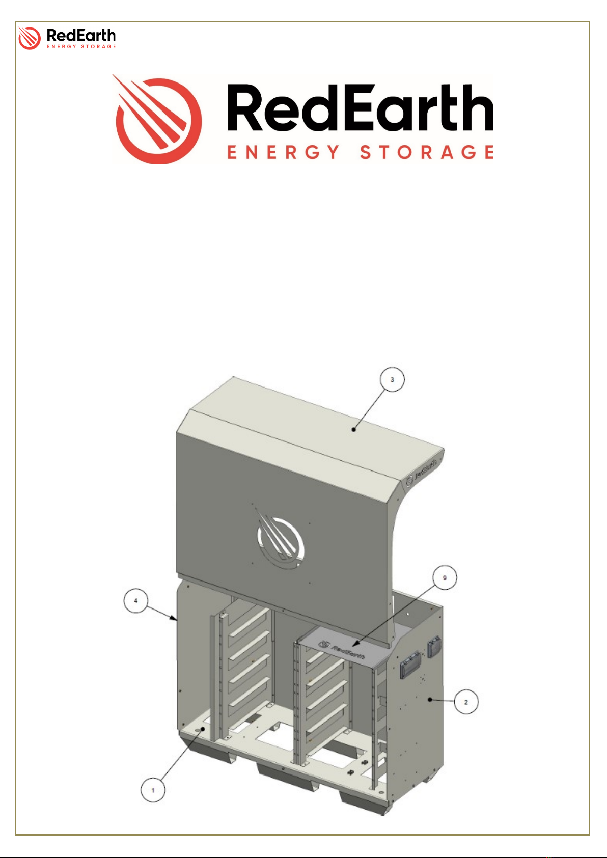
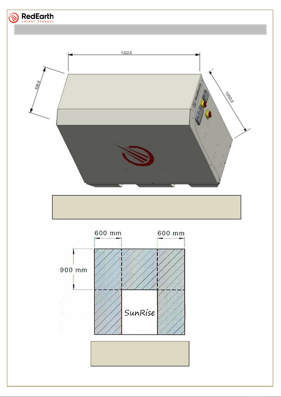
This manual describes the installation of the Model: SRS 3xx of the SunRise System.
A 1-phase version of the SunRise is also available.
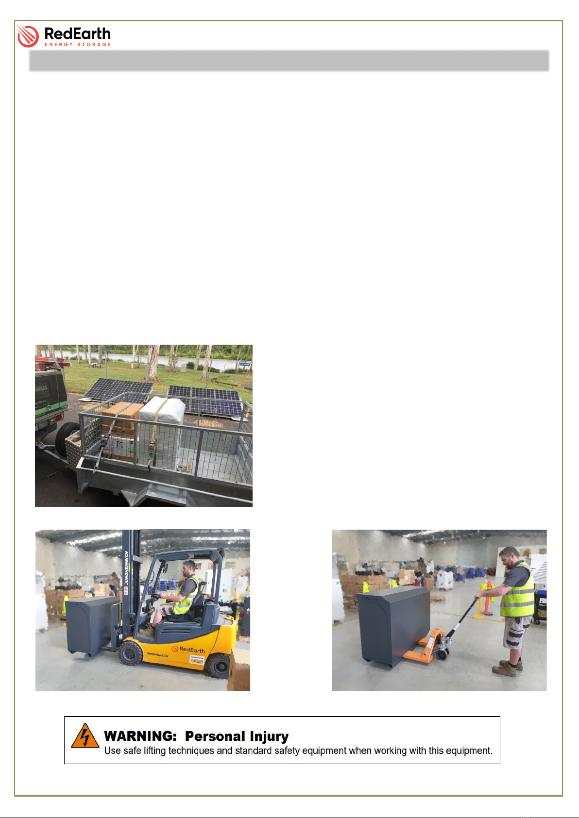
The SunRise system can be installed with or without batteries. Batteries can easily be added later,
as demand grows and budgets allow. Batteries must be of the same make and model.
•When installed with batteries excess PV solar electricity generated during the day will be
used to reduce the amount of electricity baught from the grid at night. In addition the battery
ensures essential household loads (fridges, lights etc) can be powered during a power
outage.
•When installed without batteries excess PV generated during the day can be exported to
the grid, which reduces your electicity bill. Ensuring you have the best electricity plan from
your provider will improve your return.
•The SunRise system can also easily be retrofitted to an existing PV solar system.
The SunRise combines an AS4777.2 certified SunGrow 10kW inveter (SH10RT) with the globaly
popular Pylontech lithium-ion batteries (H48074). With the advantege of scalability in energy
storage, the Sunrise has multiple options to fit a budget:
•Emergency Power:The minimum amount of batteries aloud for this SunRise is zero (0) batteries.
However, if opting for batteries, at least 5 batteries (17.75kWh) must be installed for correct
operation. This option will not provide full 10kW to EPS circuits
•Full Power:To have the maximum (10kW) power available, the Sunrise must have seven (7) or more
batteires.
•Max Storage:With the hability to hold 9 batteries, a fully loaded SunRise can store 31.95kWh of
electricity.
For government rebates purposes, a maximum of 13.3kW (1.33 x 10kW) of solar panels can be
connected to the system.
The SunRise SRS system can be remotely monitored via RedEarth Energy Storage’s platfom as
well as SunGrow’s web portal or their app (iSolarCloud app).
Overview:

SunRise – Installation Manual
RE_PROD_0018 Version 1 Page 6 of 27 Issue Date 13/11/2020
A typical complete installation of the SunRise Home Battery will require the electrical connection of
the following items:
1. Meter (supplied) in the MSB.
2. AC cables from the MSB directly to the Grid terminals inside the SunRise system.
3. AC cables from the MSB directly to the Emergency Power Supply (EPS) terminals inside
the SunRise system.
4. A standard Cat5/6 cable to connect the meter with the system.
5. Up to 3 arrays of PV solar panels to the MC4 conectors inside the unit.
6. Optional – an internet cable from the router to the system to provide more reliable
communication for remote monitoring.
In addition, the installer will need to program the Sungrow inverter for the customer’s specific
requirements (e.g. level of grid-feed allowed by the utility) Use the Sungrow iSolarCloud APP
operating in local mode for these modifications.
Once the system is up and running, the installer or end customer can call RedEarth Tech Support
and set-up the monitoring page.
Note: The SunRise is not designed to act as the customers MSB as it does not include space for
additional main & customer circuit breakers or RCDs.
Overview:

SunRise – Installation Manual
RE_PROD_0018 Version 1 Page 7 of 27 Issue Date 13/11/2020
SunRise Weight: 450kg with 9x Lithium batteries (32kg per battery)
Dimensions: 1050 H x 1322 W x 537 D [mm]
Dimensions & Clearance
Sunrise Minimum Clearance
According to AS/NZS 5139

SunRise – Installation Manual
RE_PROD_0018 Version 1 Page 8 of 27 Issue Date 13/11/2020
Opening the SunRise
RedEarth’s SunRise Home Battery System can be internally
accessed by removing the front cover. To do this, remove the nine
(9) screws with a Philips screwdriver (PH2), lift and pull the cover
away from the unit and place in a safe location.
Inside
The SunRise can be divided into three main areas. On the
Lefthand side (LHS) is the Inverter, in the middle are the batteries
and the Battery Management Unit (BMU) and on the Righthand
Side (RHS) are the electrical devices.
Lefthand Side (LHS)
Here you will find the Sungrow SH10RT facing
outwards and all the connections to it are on the
bottom side. Also in this area are the terminal
blocks that will communicate with the meter.
Middle
This general area is where the batteries are located. A complete set
will have two stacks of batteries with 5 on the left and 4 on the right.
The top slot on the right will hold the BMU.
The terminals above the batteries are for the connection of the
thermal relay and the heat extraction fans.
Righthand Side (RHS)
Here you will find all the connection points for the power cables and the
protection devices.
Access to this area is narrow and limited, this is why the connection terminals
and MC4 connectors have been brought forward for easy installation.
Components
Removal of the cover must only be
done by qualified personnel.

SunRise – Installation Manual
RE_PROD_0018 Version 1 Page 9 of 27 Issue Date 13/11/2020
The SunRise comes fully equipped with the following items.
•SunRise pre-wired enclosure
•Sungrow SH10TR inverter
•SunRise User Manual
•SunRise Installation Manual
•Battery MSDS
•Identification Sheet
•Testing Procedure
•Spare Parts Kit
oStickers and Traffolytes
o3x MC4 connectors
o1x M16 Gland
o5x M25 glands (Corrugated Conduit Adapter)
o2x Three-pole circuit breakers
Components

SunRise – Installation Manual
RE_PROD_0018 Version 1 Page 10 of 27 Issue Date 13/11/2020
8 steps for complete SunRise installation:
1. Transporting
2. Positioning
3. Solar Install
4. Electrical connections
a. Solar
b. Battery
c. Grid & EPS
d. Aux. Earth Fault Alarm
e. MSB & Meter
5. Turn on/Shutdown
6. Commissioning
7. Monitoring and Communications
8. Finalising and Handover
Step 1. Transporting
The SunRise system is wrapped in foam, heavy duty
cardboard and supplied on a pallet, is fully set-up and
ready to run. The system weighs around 450kg with 9
lithium batteries and should be handled with proper
lifting equipment.
With two slots on the base, the Sunrise can be easily
re-positioned with the help of a trolley jack or a forklift.
Installation

SunRise – Installation Manual
RE_PROD_0018 Version 1 Page 11 of 27 Issue Date 13/11/2020
Step 2. Positioning
The SunRise is designed to be a freestanding weatherproof system. However,
we strongly recommend it to be placed close (300mm) to a wall in a shaded
area to reduce the chances of overheating. It should also be placed as close
as possible to the solar panels and the MSB to minimise voltage drop/power
loss.
Cooling air flow passes up through the base of the system and then out the
back.
Air vents are included in the base and
rear of the system. Do not block them
otherwise the system will overheat and shutdown. Once the
system cools down again it can be restarted. The flow of
air is assisted by an electric fan connected to one of the
rear vents. It is controlled by an adjustable temperature
switch set to 35⁰C in the factory.
•Allow spacing around the system to comply with
current installation standards.
With the help of a trolley, you can roll the system into place
and secure it to the floor.
The SunRise has four holes in the base to allow for
securing. This can be done with dynabolts or material
appropriate screws.
NOTE: SunRise can be installed indoors. However, proper
ventilation must be installed according to AS/NZS 5139.
NOTE: Minimum distance between the wall and the back is 100mm
Step 3. Solar Install
PV Racking & Panels should be designed and installed in accordance with
AS/NZS 5033 and the latest CEC Installation guidelines. Caution should be
taken in selecting PV panels and wiring method to ensure Open Circuit
Voltage (VOC) and Short Circuit Current (ISC) is not exceeded.
Installation
SunRise Minimum Clearance
According to AS/NZS 5139
WARNING: The Solar DC Isolator on the SunRise must be in the off position
before any solar panels are connected
PV array must be floating (must not be grounded)
Ensure that the array is within the inverter specification and polarity
of the array is correct.
PV modules must have an IEC61730 Class A rating

SunRise – Installation Manual
RE_PROD_0018 Version 1 Page 12 of 27 Issue Date 13/11/2020
Step 4. Electrical connections
SunRise is designed to be an extremely easy install. SunRise, must be hardwired to a remote
switchboard, which contains a MEN and earth stake. To do so, open up the unit as explained in
“Opening the SunRise” and direct your attention to the RHS. Here are the connection point needed
for an install.
4.1. Solar
SunRise has 2 Maximum Power Point
Trackers (MPPTs) and allows for three
arrays to be installed. Two of which
connect to MPPT #1 and one to MPPT#2.
For ease installation, each MPPT has its
own isolation device and comes with the
correct amount of connection points as
allowed by the inverter.
To connect the solar power, insert the
unterminated cables into the system and
then terminate the correct MC4’s on the
cables. Once this in done, connect the PV
cables to the unit and check for correct polarity and VOC.
4.2. Battery
Tested and commissioned in RedEarth factory, the batteries can be found in the middle section of
the SunRise.
If the batteries are to be removed during final transportation/positioning, please see below the
procedure and correct arrange.
To remove the battery cables, press the button on the side of the terminal and pull it straight up.
To attach the cable to the battery, simply push it onto the terminal until you hear a click. Be careful
to connect the black cable to the black terminal and the red/orange to the red/orange. If the battery
polarity is connected incorrectly it will damage the SunRise system.
Installation
Before any electrical connections are made, check all internal connections are secure and
have not come loose during transport.
Ensure that all breakers and isolators, as well as those supplying power to the unit, are
turned OFF.

SunRise – Installation Manual
RE_PROD_0018 Version 1 Page 13 of 27 Issue Date 13/11/2020
Battery Sequence Arrange
Detailed BMU Connections
Secure BMU and Batteries with supplied screws
Installation
DIP Switch
Sequence
“000001”

SunRise – Installation Manual
RE_PROD_0018 Version 1 Page 14 of 27 Issue Date 13/11/2020
4.3. Grid
The Terminal Blocks labelled as “Grid” identify the side of the
system/MSB connected to the grid as well as the non-essential
circuits.
To connect the cables to the system, secure the exposed end of
the cable into the correct terminal block and secure by tightening
with a flat-head screwdriver to .5N•m.
4.4. Emergency Power Supply (EPS)
The Terminal Blocks labelled as “EPS” identify the side of the
system/MSB connected to the essential circuits.
To connect the cables to the system, secure the exposed end of
the cable into the correct terminal block and secure by tightening
with a flat-head screwdriver to .5N•m.
As the output is floating, the neutral cable of GRID side and EPS
side must be connected together according to the wiring rules
AS/NZS_3000. Otherwise EPS function will not work. See
Appendix A: Single Line Diagram – Main Switchboard
4.5. Auxiliary Earth Fault Alarm
RedEarth’s Sunrise has two terminal blocks for the installation of a third-party alarm. These 2
terminals are on the same din rail as the EPS terminals and can be identified by their smaller size,
with the grey terminal set as the active and the blue the neutral.
To install the third-party alarm, replace the resistor (wrapped in heat-shrink) with the new device.
All cables must be sized to appropriate Australian standards and not be less than 2.5mm²
Installation
The SunRise is compatible with type A RCD’s
Earth connection must be made to the same switchboard as the power cables
The cable for EPS must sized to support a maximum of 15.2A according to AS/NZS 3008.1.1:2017
This system complies to IEC 62109-2 clause 13.9 for earth fault monitoring.

SunRise – Installation Manual
RE_PROD_0018 Version 1 Page 15 of 27 Issue Date 13/11/2020
4.6. MSB & Meter
The Meter must be installed immediately after the main switch in the MSB and will work as a pass-
though (including the neutral) as shown.
The communication between the meter and the system can be done with a CAT5 or CAT6 cable.
Using 2 of the strands from the CAT cable, connect one (A) to the terminal 24 and the other (B) to
terminal 25, as shown.
Inside the SunRise and underneath the inverter are the terminals that the other end of this CAT
cable will connect to. Strip the end of strands A and B and connect them to the correct terminals.
.
Installation

SunRise – Installation Manual
RE_PROD_0018 Version 1 Page 16 of 27 Issue Date 13/11/2020
Step 5. Turn ON and Shutdown Procedure
All devices for Turn On procedure are located on the RHS of the unit and can be also identified by
the number in front of it.
To Turn ON the unit for the first time, you must follow the steps below:
1 Switch ON the BMU breaker;
2 Press the Power (red) button on the BMU;
3 Switch ON the BATTERY SYSTEM D.C. ISOLATOR (#3);
4 Switch ON both SOLAR D.C. ISOLATORS (#2);
5 Turn the ByPass Switch to Normal Operation (upwards);
6 Turn ON all AC circuit breakers (#1);
1
2
3
4
5
6
Installation
Steps 1 and 2 are done on the inside of the unit and must be done by a certifies electrician
only. For all other times, the Turn ON procedure is the reverse of the shutdown procedure.

SunRise – Installation Manual
RE_PROD_0018 Version 1 Page 17 of 27 Issue Date 13/11/2020
The Shutdown Procedure is the reverse of the “turn on” procedure and is shown below. This
procedure can be found on the RHS of the unit.
1 Turn OFF all AC circuit breakers (#1);
2 Switch OFF the SOLAR D.C. ISOLATORS (#2);
3 Switch OFF the BATTERY SYSTEM D.C. ISOLATOR (#3);
.
1
2
3
Installation

SunRise – Installation Manual
RE_PROD_0018 Version 1 Page 18 of 27 Issue Date 13/11/2020
Step 6. Commissioning
The SunRise is commissioned and tested in RedEarth’s factory
to guarantee correct operation of the system as ordered.
However, last-minute parameter adjustments may be required
(eg. Export limitation). The procedure below explains hot to
access the inverter via “Local Mode” on the ISolarCloud APP.
To Change parameters, carefully follow the procedure in
Chapter 8 of the Sungrow User Manual on how to make these alterations
without compromising the existing configuration.
NOTE: This must be done by a qualified person.
Disconnect 4g
Sync to the dongle WiFi;
SG-B20*****XXXX
PW: B20*****XXXX
Open the APP (iSolarCloud) and access via “Local Mode” with the following
account and password.
Fan Control Adjustment:
The thermostat is located inside the unit next to the GPO’s. This automatically starts
the fans once the temperature rises above the set-point. This set-point can easily be
adjusted with a small screwdriver. It is set to 35⁰ Celsius in the factory.
Account user
Password user or PW1111
Installation

SunRise – Installation Manual
RE_PROD_0018 Version 1 Page 19 of 27 Issue Date 13/11/2020
Step 7. Monitoring and Communication
There are currently two ways to enable monitoring to the SunRise.
•4G Antenna
•Hardwire to LAN
The first option uses RedEarth’s monitoring hardware and requires positioning the antenna in a good
4G reception area. If installing in a closed area i.e. Shed, remember to check the 4G signal with the
doors closed as this will affect the strength of the signal.
Once this is done as well as the start-up procedure, call RedEarth – Tech Support to confirm its
operation.
The second option requires a CAT5 or CAT6 cable with one end plugged into the customer’s router
and the other into the RJ45 port on the monitoring hardware.
As long as the 4G reception is adequate (or properly hardwired to the router) this does not require
commissioning as it is done and tested in factory
Step 8. Finalising and Handover
Before handing over the system, go through the following items and be sure that they have been
completed.
•The PV cables have the correct polarity and are correctly connected to the MC4s provided.
•Grid and EPS cable are tightly connected to the terminals block and have correct phase
rotation.
•Proper weatherproof seal on the entrance/exit gland from the SunRise
•The battery terminal connections are tight. (check after transportation)
•Check that the system operation is correct in all situations.
•Check screws holding the lid down are in place and tight. Pull on the vents and fans to check
that they are properly attached and will not come loose.
•Explain to the customer how the system operates.
Installation
Installer login is available in addition to customer logins. Contact Tech support for information.

SunRise – Installation Manual
RE_PROD_0018 Version 1 Page 20 of 27 Issue Date 13/11/2020
NORMAL OPERATION:
In this operation mode the Sunrise will operate as explained above. Where the system uses solar,
battery and grid depending on the situation.
All of the breakers and isolators should be on the ON position and the ByPass Switch should be in
the upwards position ( I ).
BYPASS OPERATION
In the ByPass operation mode, the system will completely bypass the inverter and the grid will
provide power directly to the EPS loads.
For this to happen, all breakers and isolators should be turned OFF and the ByPass Switch should
be in the downwards position ( II )
How to Operate a SunRise
Other manuals for SunRise SRS-3 Series
2
Table of contents
Other RedEarth Batteries Pack manuals

RedEarth
RedEarth DropBear User manual

RedEarth
RedEarth HoneyBadger User manual

RedEarth
RedEarth TROPPO-4841 User manual

RedEarth
RedEarth BlackMax User manual

RedEarth
RedEarth BlackMax User manual

RedEarth
RedEarth DropBear User manual

RedEarth
RedEarth BlackMax User manual

RedEarth
RedEarth SunRise SRS-3 Series User manual