RedEarth BlackMax User manual

Installation and Operation Manual
BlackMax
Off-grid and on-grid battery system
The first Australian-made off-grid
battery energy storage system
approved by the Clean Energy Council,
now with new and improved features.

BlackMax – Installation and Operation Manual
Page 2 of 36
Issue date: 24/11/2023. Version 13.0
Safety instructions
The wiring diagrams and installation instructions are given as a guide only and compliance to appropriate standards is
the responsibility of the installer. Relevant standards are listed below:
AS/NZS 3000:2018
Wiring rules
AS/NZS 5033:2021
Installation and safety requirements for photovoltaic (PV) arrays
AS/NZS 4509.2:2012
Stand-alone power systems-Design
AS/NZS 1170.2:2021
Structural design actions-Wind actions
AS/NZS1768:2021
Lightning protection
AS/NZS 3008.1.2:2017
Electrical installations – Selection of cables
AS/NZS 5139:2019
Electrical installations-Safety of battery systems for use with power
conversion equipment
The BlackMax must only be installed by suitably qualified personnel who have read and are familiar with its operation
and hazards.
The BlackMax must only be installed by suitably qualified personnel who have read and are familiar with its operation
and hazards.
This manual covers all following model numbers: BMX-104, BMX-108, BMX-112.
In our efforts towards constant product enhancement, this document is subject to change at any time. Please visit
www.redearth.energy and download the appropriate and latest version manual.
Lifting hazard
The BlackMax is heavy. Observe proper lifting techniques. To reduce
the weight the Troppo batteries can be removed via the panel in the
rear of the system.
Fire
The BlackMax uses RedEarth's Troppo battery. This is a lithium-iron-
phosphate based battery (LFP). It is the safest lithium chemistry.
However, in the case of a fire the following steps should be taken. A dry
agent fire extinguisher should be readily available and used. DO NOT use
water. Evacuate the area and call emergency services. To x i c gas may be
produced if the battery catches fire.
Note:
The SDS document for the Troppo Battery can be found at
www.redearth.energy
Damaged battery
Do not use a damaged battery. Batteries should only be disposed of at
an appropriate recycling centre. Please contact RedEarth for advice.
WARNING:
Working on the inside of the BlackMax system is restricted to qualified personnel.
RedEarth recommend installation by licensed electricians only.

BlackMax – Installation and Operation Manual
Page 3 of 36
Issue date: 24/11/2023. Version 13.0
Ta b l e o f C o n t e n t s
Safety instructions ........................................................................................................................................................................................................................... 2
Overview .............................................................................................................................................................................................................................................. 4
Dimensions.......................................................................................................................................................................................................................................... 5
Description of the BlackMax........................................................................................................................................................................................................ 5
Opening the BlackMax............................................................................................................................................................................................................. 5
Inside layout ................................................................................................................................................................................................................................. 5
BlackMax Components ........................................................................................................................................................................................................... 6
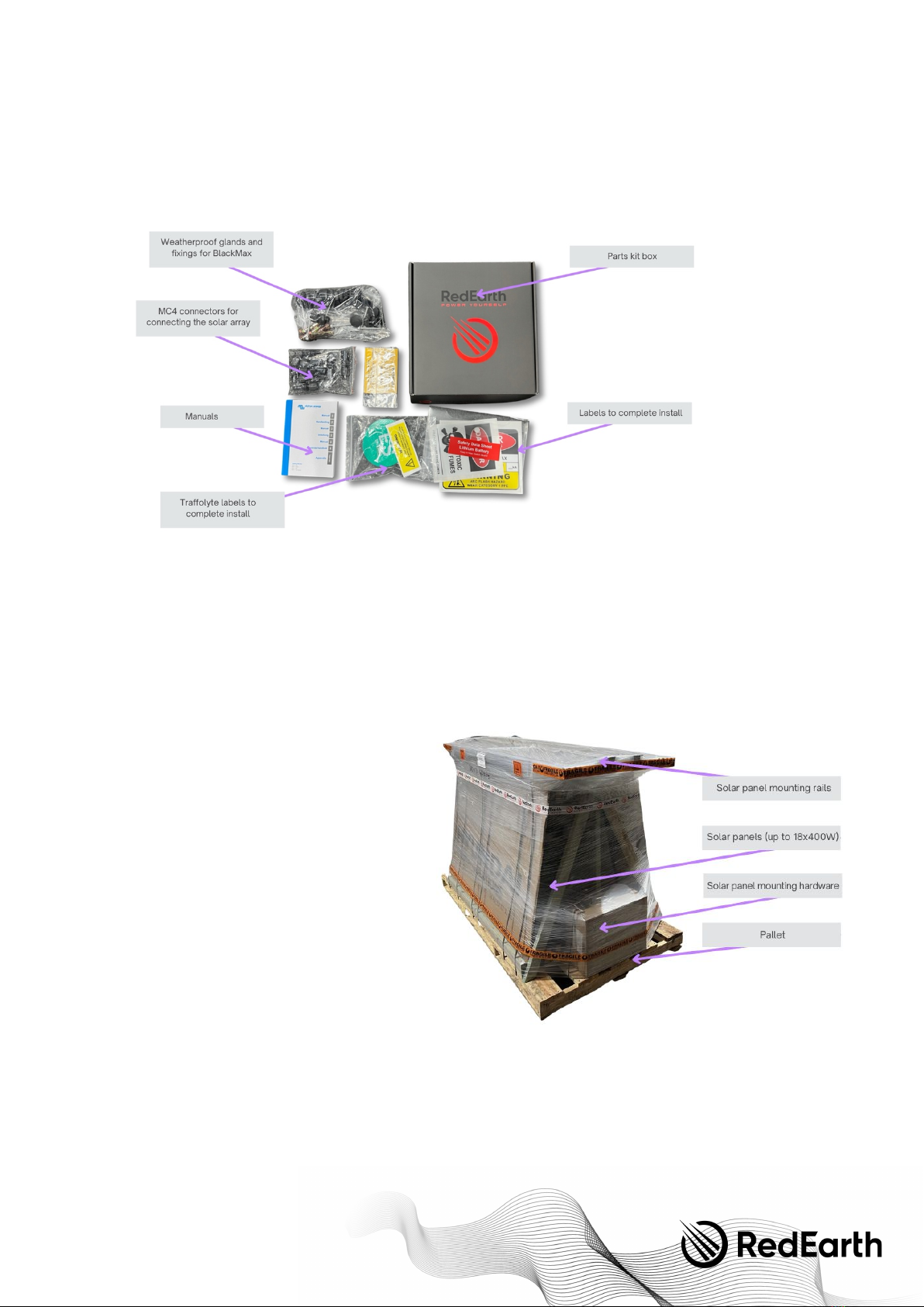
Parts kit ........................................................................................................................................................................................................................................... 7
Complete BlackMax PowerStation kit (option)............................................................................................................................................................... 7
Installation ........................................................................................................................................................................................................................................... 8
Step 1. Transporting the BlackMax..................................................................................................................................................................................... 8
Step 2. Positioning the BlackMax ........................................................................................................................................................................................ 9
Step 3. Solar array sizing and layout.................................................................................................................................................................................. 9
Step 4. Electrical Connections .......................................................................................................................................................................................... 11
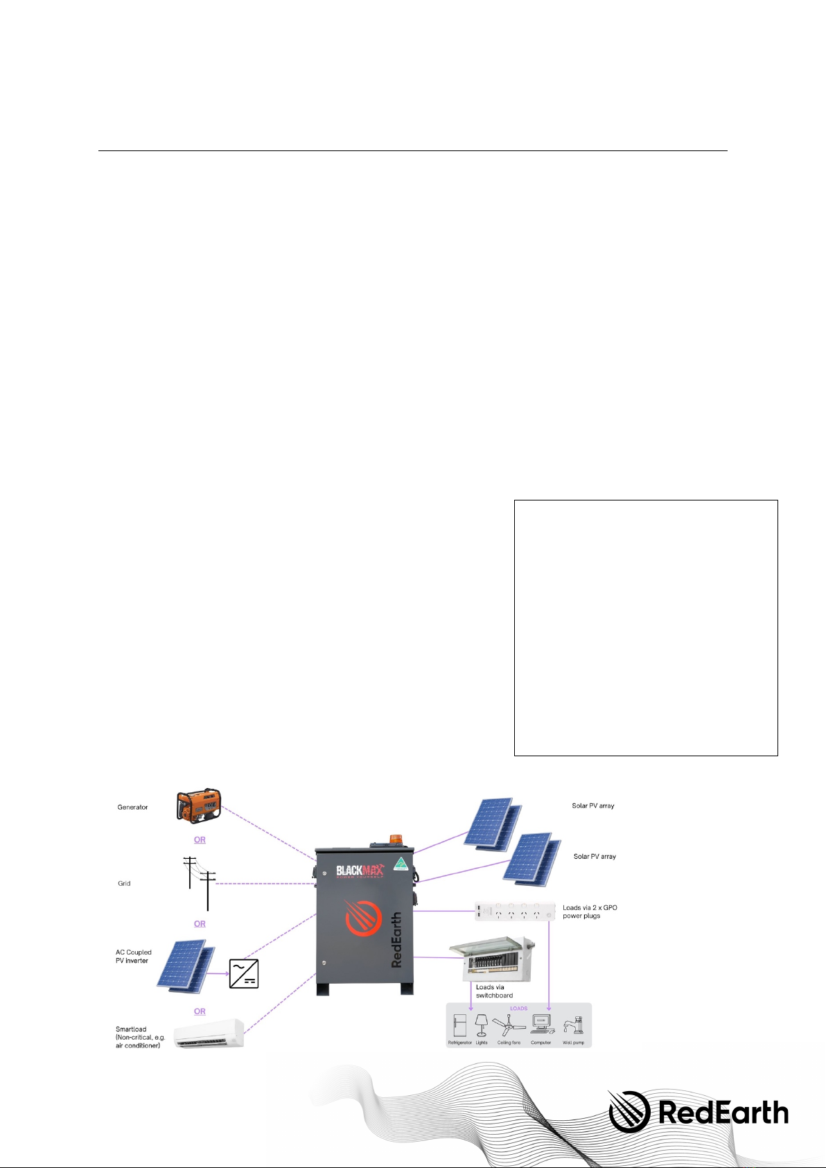
4.1 Overview of the connection layout.................................................................................................................................................................. 11
4.2 Solar array connection.......................................................................................................................................................................................... 11
4.3 Battery connection................................................................................................................................................................................................. 11
4.4 Load connection...................................................................................................................................................................................................... 13
4.5. AC source connection........................................................................................................................................................................................... 13
4.6 Flashing light connection (or generator auto-start connection—optional) ..................................................................................... 15
4.7 Remote monitoring system—connection (optional)................................................................................................................................. 15
Step 5. Commissioning the BlackMax............................................................................................................................................................................ 16
Tu r n i n g O N t h e B l a c k M a x ............................................................................................................................................................................................... 16
Shutdown procedure ....................................................................................................................................................................................................... 16
Adjusting the inverter parameters .............................................................................................................................................................................. 17
BlackMax Fault Codes .................................................................................................................................................................................................... 21
Victron BMV setup - State-of-charge measurement .......................................................................................................................................... 22
Fan Control Adjustment .................................................................................................................................................................................................. 23
Te s t t h e o p e r a t i o n o f t h e b a c k u p g e n e r a t o r , i f a v a i l a b l e . ................................................................................................................................. 23
Flashing light alert............................................................................................................................................................................................................. 23
Generator 2-wire auto-start........................................................................................................................................................................................... 23
Step 6. Monitoring the BlackMax...................................................................................................................................................................................... 24
Step 7. Finalising installation and customer handover............................................................................................................................................. 26
FAQs and Trouble shooting ....................................................................................................................................................................................................... 28
Services and options available for the BlackMax ............................................................................................................................................................ 29
Appendix A....................................................................................................................................................................................................................................... 30
Single Line Diagram: Power................................................................................................................................................................................................. 30
Single Line Diagram: Communications............................................................................................................................................................................ 31
Single Line Diagram: Generic Main Switchboard........................................................................................................................................................ 32
Appendix B....................................................................................................................................................................................................................................... 33
Technical Specifications: BlackMax................................................................................................................................................................................. 33
Te c h n i c a l S p e c i fi c a t i o n s : D e y e S U N -6K-SG04............................................................................................................................................................ 34
Te c h n i c a l S p e c i fi c a t i o n s : R e d E a r t h Tr o p p o b a t t e r y .................................................................................................................................................. 35

BlackMax – Installation and Operation Manual
Page 4 of 36
Issue date: 24/11/2023. Version 13.0
Overview
RedEarth’s
updated BlackMax
battery system is a complete ready-to-run energy storage system for off-grid and on-grid
applications. It is available as either a battery system alone or as a complete PowerStation kit including solar panels and solar
panel mounting equipment, all on two pallets. As an Australian-made product built in Brisbane, RedEarth can provide best-in-
class support for BlackMax owners and installers.
The battery system arrives fully assembled and factory tested. It includes a 6kVA hybrid inverter with two built-in single string
MPPTs for connecting solar panels. It can be supplied with up to three (3) of RedEarth's Troppo lithium batteries (12.3kWh total).
Note that to use the full power available from the inverter at least 2 Troppo batteries are required.
The BlackMax system is designed to be installed either inside or outside, ideally in a shaded area. All switchgear required for
installation is built in. No need to screw switches to the wall.
A typical installation of the BlackMax with solar panels, will require the electrical connection of:
1.
Solar:
Directly connect the solar arrays to the two built-in PV MCBs with pre-terminated MC4 plugs inside the system.
(do not exceed 500Vmax on the PV arrays)
2.
Load
: There are two GPO power points on the system to plug loads into directly (one 15amp & one 10amp) or hard-
wire an external sub-board to the terminal block inside the BlackMax (to access the full 6kVA of power available)
3.
Earth and MEN link:
These need to be in place as required by national standards.
4.
Generator or grid:
Directly connect a hard-wired generator. The generator can be set up for either manual or 2-wire
auto start. Note: it is mandatory to test that the generator works with the BlackMax during installation. Instead of a
generator a single-phase grid supply can be connected to the same hard-wire terminal blocks to achieve generator
like performance from your grid supply.
•
Note:
As an alternative to a generator or grid supply, a different AC-coupled renewable energy source can be
connected to the generator terminals in the BlackMax. This could be an additional Solar PV inverter or Micro-
Inverter system. The BlackMax needs to be pre-configured for one of these options. By default, the BlackMax is
set up for a generator. Therefore, please inform RedEarth before connecting the system to an alternative
renewable energy source.
There are several ways to monitor the BlackMax.
• Local monitoring via the battery SOC meter (state-of-charge) on the top
of the unit.
• The two Power meters on the side of the unit. One shows power in
from the generator and the other shows total power out of the inverter
to the loads.
• Flashing orange light. This turns on when the SOC drops below the set
point (it is factory-set to 20%).
• Remote monitoring: The BlackMax includes an industrial grade
monitoring kit to enable remote monitoring and control capabilities. To
activate this service, the owner needs to enrol in RedEarth's Optimum
program which includes ongoing monitoring of the BlackMax system by
RedEarth. Note that this requires mobile phone coverage or another
source of internet (e.g., Starlink, which RedEarth can assist with).
• RedEarth's EMU app. Once remote monitoring is activated the
BlackMax can be monitored from the customer’s mobile phone.
Note:
The BlackMax is not designed to act as a main switchboard for the
premises, as it does not include space for additional main and customer circuit breakers or RCDs. The MEN link and Earth
connection need to be in place at the premises as required by national standards.
Qualified installation person (installer)
The installation tasks described in this manual
should be carried out by a suitably qualified and
skilled electrician with adequate skills,
qualifications, and experience. They should:
• Have a thorough understanding of
operations, design, and installation
principles of on- and off-grid electrical
systems.
• Have a thorough understanding of the risks
and dangers associated with installing and
using electrical equipment.
• Hold all local, state and country-based
qualifications to carry out such work.
• Adhere to all safety and installations
requirements contained in this manual.
• To c l a i m the STC's available for the solar
panels they must be an accredited installer

BlackMax – Installation and Operation Manual
Page 5 of 36
Issue date: 24/11/2023. Version 13.0
Dimensions
Description of the BlackMax
Opening the BlackMax
RedEarth’s BlackMax energy storage system can be accessed via the
top (lid) or the front door.
To o p e n t h e l i d , 2 s c r e w s ( o n e f r o m e a c h s i d e) m u s t b e r e m o v e d a n d
then the lid can be lifted and pivoted on the rear hinge.
To a c c e s s f r o m t h e f r o n t , t h e r e a r e 2 l o c k s o n t h e f r o n t d o o r . T h e k e y
to open these locks comes tied to the left handle and must be kept
out of the reach of children.
Inside layout
The BlackMax is divided internally into four main areas, The AC
electrical switchgear, the DC electrical switchgear, the inverter, and
the battery area.
Opening the front door provides
access to the AC side, inverter area,
and DC side. To access the AC or DC
side, you will have to remove the
clear plastic safety covers that are
held in place by 3 nuts.
Note:
Do not over tighten the nuts
holding the clear plastic cover in
place as they will crack under
pressure
.
To access the battery area, either
open the top lid or remove the
screws holding the rear panel in
place. Removing and replacing
batteries is easiest via this rear panel.
The BlackMax
weighs 176kg
when fully loaded
with three (3)
Troppo batteries.
Each battery
weighs 43kg and
can be removed
for ease of
handling.
The empty
BlackMax weighs
74kg.

BlackMax – Installation and Operation Manual
Page 6 of 36
Issue date: 24/11/2023. Version 13.0
BlackMax Components
The main components of the BlackMax includes the hybrid inverter one, two or three lithium Troppo batteries and the pre-wired
enclosure containing all the other electrical components as shown in the picture below.

BlackMax – Installation and Operation Manual
Page 7 of 36
Issue date: 24/11/2023. Version 13.0
Parts kit
The BlackMax system is supplied with a parts kit containing all the addition items needed to complete the installation.
Complete BlackMax PowerStation kit (option)
RedEarth also provides a convenient BlackMax PowerStation kit. This includes the BlackMax on a small pallet and the solar
panels as well as all mounting equipment for a typical tin roof on a second pallet as shown.
The PowerStation kit includes the following items,
• BlackMax (with 1, 2 or 3 Troppo lithium batteries)
• 15A lead for connecting a typical
small generator.
• Note that no generator is provided
however RedEarth can recommend
some models that work with the
BlackMax.
• Solar Panels (up to 18 x 400W panels
= 7.2kW) subject to change as panel
sizes continue to increase
• Clenergy solar panel mounting
hardware and rails for tin roof along
with required PV cables.
o The list below shows the
parts included for an order
with 16 solar panels.
o The PV rails are cut in half
to be 2.1m long (additional
PV rail splices are included)
• Dimensions for the solar panel kit
pallet (1.2m wide x 2.1m long x 1.4m
high)
• Weight of solar panel kit pallet weight
= 450kg (16 panels)

BlackMax – Installation and Operation Manual
Page 8 of 36
Issue date: 24/11/2023. Version 13.0
WIISE
SKU
Description
Oty.
Unit
CH001010
SKU
BlackMax 16 Panels Mounting Kit—Tin Roof
|1377
SKU-001
SPLICE PLATE, PV-EZRACK, SUITS ECO RAIL
16.
EA
|1378
SKU-002
TIN INTERFACE KIT
40.
EA
|1379
SKU-003
CABLE CLIP, PV-EZRACK FOR PV PANELS, HOLDS 2 CABLES, BOX OF
900
64.
EA
|1380
SKU-004
CLAMP, UNIVERSAL MID/END WITH GROUNDING CLIP
50.
EA
|1382
SKU-006
GROUNDING LUG, PV-EZRACK
6.
EA
|1384
SKU-008
RAIL, PV-EZRACK ECO 4200MM LONG ALU/STEEL, BUNDLE OF 90
9.
EA
|1394
SKU-018
SWITCH, ZJ BENY DC ISOLATOR 32A 4 POLE 1200V
1.
EA
|1395
SKU-019
COVER, ZJ BENY ISOLATOR
1.
EA
|1134
CON-015
CONNECTOR, MC4 BRANCH MALE
1.
EA
|1135
CON-016
CONNECTOR, MC4 BRANCH CONNECTOR FEMALE
1.
EA
|1961
CON-017
CONNECTOR, MC4 STANDARD MALE & FEMALE (1 x BAG = 5)
10.
EA
|1078
CBL-021
CABLE, 2C x 4MM2 DC SOLAR (9PV-1F), 0.9/1.8KV
25
P/M
|1095
CBL-038
CABLE, 4MM2 SINGLE CORE DC SOLAR (PV-1F)
25
P/M
|1297
PLT-002
PALLET, WOOD 2100MM x 1170MM (BlackMax with PV only)
1
EA
Installation
7 steps to complete your BlackMax installation:
1. Transporting the BlackMax
2. Positioning the BlackMax
3. Solar array sizing
4. Electrical connections to the BlackMax
5. Commissioning the BlackMax
6. Monitoring and communication
7. Finalising installation and customer handover
Step 1. Transporting the BlackMax
The BlackMax system is supplied on a pallet in one of two configurations (just the
BlackMax on a small pallet or as a complete PowerStation kit on a larger pallet) as
shown below.
The BlackMax weighs 203 kg (with 3 batteries installed). Each battery weighs 43kg.
The solar panel kit with 16 solar panel weighs 450 kg shown below.
RedEarth’s BlackMax comes fitted with two handles to help with handling. However, it
is a heavy unit and should be handled with a transportation device such as a hand
trolley. (
Note:
if using a hand trolley, you may need to click the bottom vents back into
place after finishing using the trolley).
The lithium batteries can also be removed via the panel in the rear of the BlackMax,
and replaced once the system is in position. Each Troppo battery module weighs
43kg. The empty BlackMax weighs 74kg.
WARNING: Personal Injury
Use safe lifting techniques and standard safety equipment
when working with this equipment

BlackMax – Installation and Operation Manual
Page 9 of 36
Issue date: 24/11/2023. Version 13.0
Step 2. Positioning the BlackMax
The BlackMax is designed to be a freestanding weatherproof system (suitable for outdoor locations).
It is recommended to locate the system in a shaded area to reduce the
chances of overheating. It should also be placed close to the solar panels to
minimise voltage drop and power loss.
The BlackMax can be secured to the ground via the four holes in the feet of the
system. This can be done with the Dynabolts, or screws supplied in the Parts
kit, or other material appropriate fixings.
Clearance:
Allow 600mm spacing on both sides
of the BlackMax.
If positioning the BlackMax against
the wall of a habitable room, then the
clearance requirements are as per
AS5139 and shown at right, must be
observed. In addition, the wall should
be made of non-flammable material,
if it is a habitable room.
Note: If the BlackMax is placed at
least 300mm off the wall of any
building, then these requirements of
AS5139 do not apply.
Ventilation:
Cooling air flow passes up through the vents in the base of the system and then out the fan located on the top left-hand side of
the unit. Do not block the air vents as the system may overheat and shutdown. If the BlackMax does shutdown because of
overheating, it will automatically restart once it cools down again. The fan is controlled by a temperature switch set to 25
⁰
C in
the factory, which can be adjusted on site.
Step 3. Solar array sizing and layout
The PV Array should be designed and installed in accordance with AS/NZS 5033 and
the latest CEC Installation guidelines.
Caution should be taken in selecting PV panels and the wiring method to ensure the
rated Open Circuit Voltage (Voc) and Short Circuit Current (Isc) is not exceeded
(factoring in the coldest and hottest expected ambient temperatures).
The maximum Voc for the BlackMax is 500Vdc. This usually means a maximum 9 panels
in series when using typical 400 Watt panels.
The maximum Isc is 19.5 amps. This means a maximum of one string in parallel when
using typical solar panels. (<15.6A per panel taking into consideration the 1.25x derating
factor of Isc, used in Australia)
BlackMax Minimum
Clearance
According to AS/NZS
5139

BlackMax – Installation and Operation Manual
Page 10 of 36
Issue date: 24/11/2023. Version 13.0
Note that the BlackMax has two MPPTs, so PV panels can be installed facing in two different directions.
Example calculation of maximum number of solar panels in the array:
Below are the specifications of a typical 400W panel that RedEarth supplies in the complete BlackMax PowerStation kit (as of
December 2023).
Electrical characteristics
400W panel
Mono-Crystalline Module (HiE-S_____UF)
Maximum Rating Power (Pm)
W
400
Open Circuit Voltage (VoC)
V
49.5
Short Circuit Current (Isc)
A
10.12
Maximum Power Voltage (Vmp)
V
41
Maximum Power Current (Imp)
A
9.76
Module Efficiency
%
21.3
Maximum System Voltage
V
DC 1,500
Temperature Coefficient of Pmax
% / °C
-0.340
Temperature Coefficient of Voc
% / °C
-0.270
Temperature Coefficient of Isc
% / °C
+0.040
Maximum number of panels in series (Max. PV array voltage):
For the 400W panel shown above, Isc is 10.12 Amps at 25degC. If the highest expected temperature is 50degC then the
temperature correction is +25degC x +0.040% = +1.00%. This means that at 50degC the Ioc is 1.00% higher than at 25degC =
1.010 x 10.12 = 10.22Amps.
As the temperature increases the Ioc Increases which is why the highest temperature is important for Ioc calculations.
The Isc rating of the BlackMax Is 19.5A per MPPT. In Australia the Isc rating is decreased by 1.25x to get the usable Isc. This
means a maximum of 19.5/1.25 = 15.6 Amps Is allowed according to the Australian standards.
This means that a maximum of one (1) string can be connected in parallel.
Total maximum number of panels:
This means that a total of 18 x 400W panels with these specifications can be connected to the BlackMax. This is 18 x 400W =
7.2kW.
To achieve closer to the maximum 7800W rating of the BlackMax inverter is recommended to seek lower voltage panels that
remain within the short circuit current limit of 15.6A Isc.
An example of this is the Tindo Karra 410W, specs below:
Electrical Characteristics
108 Cell Module
Karra – 410G2H
Item
Unit
*STC
*NMOT
Max. power (Pmax)
Wp
410
301
Max. power voltage (Vmp)
V
31.11
28.6
Max. power current (Imp)
A
13.18
10.5
Open circuit voltage (Voc)
V
37.11
34.3
Short circuit current (Isc)
A
13.93
11.3
Panel efficiency
%
20.6
Positive power tolerance
W
0 + ~ 5
*STC (Standard Test Condition): 1,000 W/m2, AM 1.5,25
°
C/ *NMOT (Nominal Module Operating Temperature): 800W/m2, 20°C, wind speed 1m/s,
Tolerance of Pmax, Voc &Isc ± 3% within each watt class at STC.
WARNING
The Solar DC circuit breaker on the BlackMax must be in the
off position before any solar panels are connected

BlackMax – Installation and Operation Manual
Page 11 of 36
Issue date: 24/11/2023. Version 13.0
Step 4. Electrical Connections
Before any electrical connections are made, check all internal
electrical connections are secure and have not come loose during
transport.
Ensure that all breakers, as well as those supplying power to the
unit, are turned OFF.
4.1 Overview of the connection layout
To access the full 6kVA power of the BlackMax the load needs to be hard wired to terminals inside the unit, usually via an
external switchboard. The two power points are rated at 15A (3.6kW) and 10 amps (max. 2.4kW).
Earthing the Unit: The unit should be earthed to an appropriate earth stake. The earth cable can be connected to the earth bar
(or terminal block) inside the unit with the cable passed out through the second 25mm gland on the lower left side of the
BlackMax. Alternatively, the BlackMax can be earthed via an external switchboard with an Earth stake installed.
MEN Link: There is a MEN link installed in the BlackMax. If an external switchboard contains a MEN link, then the one inside the
BlackMax should be removed & the BlackMax hard wired to the main switchboard.
The generator should be hard-wired to the terminal block inside the unit. Alternatively, an AC coupled renewables sources or
the grid connection can be hard-wired to the same terminal block inside the unit. Please note, the BlackMax doesn't support the
concurrent operation of a generator and either the grid supply or an AC-coupled renewable energy source. The inverter needs
to be pre-configured for one of these options. By default, the BlackMax is set up for a generator. Therefore, please inform
RedEarth before connecting the system to an alternative renewable energy source. See section 4.5 AC Source Connection
below.
4.2Solar array connection
For ease of installation, the BlackMax comes with its own PV
isolation MCBs and pre-terminated MC4 connectors on the
inside of the unit, as shown.
To c o n n e c t t h e s o l a r p o w e r , take the two cables coming from
each Solar array, insert the unterminated cables through the
hole on the right side of the system using a 25mm
weatherproof gland from the Parts kit. Then terminate the
correct MC4’s on the cables once it is inside the unit. Suitable
MC4 connectors are included in the Parts kit. Next, check for
correct polarity and Voc at the isolator terminals,
Then, with the BlackMax PV breaker still in the off position
connect the PV cables from the solar array to the pre-
terminated MC4 cables inside the unit. The PV array is now
ready to be used.
When exposed to light, photovoltaic (PV) array supplies D.C.
voltage to the Inverter.
Installing a PV array with voltage or current values above the
inverter rating will damage the BlackMax unit and will void the
warranty.
4.3Battery connection
The RedEarth Troppo batteries are shipped inside the unit and can be found in the rear section of the BlackMax.
For transportation or maintenance or to add an additional Troppo battery, the batteries can be accessed from the top by lifting
the lid, or from the rear by removing the rear panel.

BlackMax – Installation and Operation Manual
Page 12 of 36
Issue date: 24/11/2023. Version 13.0
Removing or Installing a TROPPO:
ATTENTION
If the battery polarity is connected incorrectly, it will damage
the BlackMax system.

BlackMax – Installation and Operation Manual
Page 13 of 36
Issue date: 24/11/2023. Version 13.0
4.4Load connection
There are two ways to connect the loads.
First, via the external 15A and 10A power points. Simply plug in a device to the
GPO's labelled Power Output. Note that each plug can also accept 10A plugs.
Note also that this output is limited to 15 Amps (approximately 3.6kW) and 10A
(approximately 2.4kW).
Alternatively, an external switchboard can be hard-wired to the BlackMax by attaching the active, neutral and earth to the
terminal's blocks labelled “Loads” on the inside of the unit. See pictures at right. This provides access to the full 6kVA rating of
the BlackMax. An example of an external generator connected to the BlackMax is shown here.
If the BlackMax is hardwired into a switchboard,
RedEarth recommends it be connected to an
appropriately rated circuit breaker. This MCB should be
installed on the far left- hand side of the switches on
the DIN rail inside the switchboard. It should also
contain the MEN link and a suitable Earth. The MEN link
inside the BlackMax is then removed (see image).
NOTE:
This Switchboard must contain all
necessary stickers and traffolytes, i.e., PV and
ES. These can be found in the Parts Kit box.
4.5 AC source connection
There are several options for connecting AC sources to the BlackMax.
A unique feature of the BlackMax is that the generator input port is very versatile and can also be factory configured to act as
an AC output port.
4.5.1 Generator solar connection—to generator terminals inside the BlackMax

BlackMax – Installation and Operation Manual
Page 14 of 36
Issue date: 24/11/2023. Version 13.0
As the BlackMax is often installed as an entirely off-grid system it is strongly recommended to have a generator available to
provide extra energy during periods of extended overcast conditions or heavy usage.
A generator can be used to run the loads and charge the batteries if they become depleted during the night, and you do not
want to wait until the morning for the solar panels to start recharging the batteries. You can also top up your batteries with the
generator if you are expecting poor weather conditions or heavy usage.
Note that the default battery charging rate is set to 1.5kW. This can be adjusted depending on the size of the generator
available. Max. 40A constant P/through.
The generator is hardwired to the BlackMax. Simply connect the active, neutral and earth from the generator to these terminal
blocks, via a 25mm gland from the Parts kit. This allows up to 6kVA to be provided by the generator, assuming it is of sufficient
size. See the Commissioning Section - Step 5 below to adjust the amount of power the BlackMax will draw from the generator.
An optional generator auto-start feature is available in the BlackMax if the generator is set-up for 2-wire auto-start, see Section
4.6 below.
The following generator specifications must also be met for a guaranteed compatibility with the inverter. Ideally an Inverter-
Generator is used as these provide more stable output power. RedEarth can also recommend generators that work with the
BlackMax.
- Generator waveform THD: < 10%.
- Generator Vrms range: 180 ~ 264Vac
- Generator voltage crest factor (Vpeak/Vrms): < 1.6
- Generator peak voltage: <380V
- Frequency range: 45Hz ~ 55Hz
- Frequency slew rate: <0.3Hz/sec
4.5.2 Grid connection—to generator terminals inside the BlackMax
When connecting the grid to your BlackMax it is best to think of the grid supply like a
generator. When connecting the grid like a generator the grid will run between a pre-
determined battery voltage range. In other words, the grid will begin charging automatically
when the batteries are low, and automatically stop when the batteries return to a healthy
state of charge. When connecting the grid in this form, no extra connection work is required,
simply connect the grid into the same generator terminals.
NOTE:
The grid is limited to 1.5KW by default, if you wish to increase this, please contact
RedEarth of follow the steps outlined later in the manual. See section "Adjusting the inverter
parameters".
4.5.3 AC-coupled solar inverter connection—to generator terminals inside the BlackMax
Instead of a generator (or the grid) an extra AC-coupled renewables source, like a Fronius inverter
can be used. This may be of interest in remote sites where supplying diesel generators with fuel is
too expensive or difficult.
Having oversized PV generation capacity means that even in overcast periods there is enough
PV being generated to keep the site operating without the need for diesel generator backup.
Note that additional battery capacity may be required.
In this case it is important you adjust the system configuration as by default the BlackMax will
expect a generator connection. To a c c o m m o d a t e t h i s change, follow the steps outlined in
section "Adjusting the inverter parameters" or contact RedEarth support before connecting
any alternative AC Source. Select "Micro Inv Input". This setting utilizes generator input port as
a micro-inverter for grid inverter input (AC coupled). This is compatible with all frequency
shiftable "grid-tied" inverters.
4.5.4 Smart load output connection
Don't have a generator or an AC coupled source? Don't fret, we can customise this port to add more value to your BlackMax
System.
The generator input terminals can also be configured to act as a controlled AC output. It could be used to run an air-conditioner
and be switched off once the battery reaches a pre-set state-of-charge.

BlackMax – Installation and Operation Manual
Page 15 of 36
Issue date: 24/11/2023. Version 13.0
Smart Load Output Mode:
This mode activates when battery SOC and PV power surpass user-set thresholds.
For example. Turn on your air conditioning system: ON at 100%, OFF at 95%. In this
example you’re aircon turns on automatically when PV power exceeds 500W and
battery SOC is 100% and turns off automatically when battery SOC is below 95%.
Like connecting an AC Coupled Source - it is important to adjust the system
configuration during installation as by default the BlackMax will expect a generator
connection.
To a c c o m m o d a t e t h i s c h a n g e , f o l l o w t h e s t e p s o u t l i n e d in section "Adjusting the inverter parameters" or contact RedEarth
support before connecting any additional AC Source.
4.6 Flashing light connection (and generator auto-start connection)
Flashing light to indicate low battery SOC:
The BlackMax comes with a pre-wired orange light that begins flashing when the state-of-
charge (SOC) of the battery drops to 20% or the battery voltage drops below 51 volts,
whichever comes first.
This is meant as a signal that it is time for the user to either reduce their loads until the
sun returns in the morning or to start their generator now. If an auto-start generator is
connected, then it should have already started before the orange light starts flashing. If it
has not, then there may be an issue with the generator (e.g., starter battery is flat).
The flashing light will continue until the battery reaches an SOC of 40% or 54.0 volts at which point the battery will usually have
enough charge to continue until the sun comes up in the morning. The generator can be run as long as desired, remembering
that it will typically charge the batteries at 1.5kW. So, if the generator runs for 2 hours it will add 3kWh to the batteries.
Generator 2-wire auto-start (dry contact):
In addition to the flashing light a 2-wire auto start cable can be installed to automate the
generator running. This requires a suitable generator with 2-wire auto-start feature. The
flashing light will remain available as we provide two dry-contact points in the BlackMax.
This is done by inserting the two wires from the generator auto-start into the NO and COM
terminals marked "Generator Auto Start".
A 2-wire auto-start cable is not supplied by RedEarth.
Tip:
When using an AutoStart generator, install a small battery charger on the generators
battery so it does not discharge over time. Otherwise, the generator should be operated
each week to charge the starter battery. RedEarth can supply a suitable charger for an additional cost.
4.7 Remote monitoring system—connection (optional)
When the BlackMax was initially purchased, the monitoring device will already be installed, setup and tested in the factory.
Remote monitoring allows the BlackMax to be monitored from anywhere using RedEarth's EMU app.
Note that it requires
mobile phone coverage to work
. Another internet source can be used, e.g., local WiFi from Starlink, which RedEarth can assist
with. 4G can be used if you join Optimum via the RedEarth EMU app.
See image on right of a BlackMax with the remote monitoring
equipment installed and a guide to where to run the antenna cable.
To fi n a l i s e i n s t a l l a t i o n o f t h e remote monitoring system:
1. Position the antenna in an area that maximises reception
of the mobile phone signal. The antenna is already
connected to the BlackMax.
2. Have the customer register their BlackMax by scanning
the QR code on the outside of the BlackMax. This allows
them to setup their monitoring as explained in Section 6.
Monitoring the BlackMax. Once this is done and the start-
up procedure has been completed, call RedEarth – Te c h
Support to confirm that remote monitoring is working.
Note that an Installer login is available in addition to customer logins.
3. Sign up for RedEarth’s Optimum service to enable monitoring—This comes with a monthly fee to cover the ongoing
monitoring data costs (3/4G SIM). It also includes monitoring by RedEarth to provide additional peace-of-mind and to
simplify any required trouble shooting. Finally, the customer becomes a member of the RedEarth community and as
such can choose to receive regular updates relevant to their electricity usage.

BlackMax – Installation and Operation Manual
Page 16 of 36
Issue date: 24/11/2023. Version 13.0
Step 5. Commissioning the BlackMax
Tu r n i n g O N t h e B l a c k M a x
To
turn on
the BlackMax follow the steps below:
1. Open the lid (remove the two screws at the front left and right first), switch ON the battery breakers on the top of each
Troppo battery. The LED and display on each battery will come on. Check that the battery voltage on the displays is
reading between 48 and 55 volts. Close the lid.
2. Switch ON the BATTERY SYSTEM D.C. ISOLATOR (#4), found on the right side of the unit. The Victron battery monitor on
the top of the system will come on at this time as it is monitoring the overall DC battery status. It indicates the state-of-
charge (SOC) of the batteries. It provides the most accurate readings of SOC. Note that when the system is initially
installed it may take a few days for the SOC to calibrate, which occurs once the system has gone through a few charge-
discharge cycles. This also applies if an extra battery has been added to the system later (In this case also don't forget to
update the battery size in the Victron monitor so it can calculate SOC correctly, see instructions in the
Adjusting the
Inverter Parameters
in the section below)
3. Switch ON the SOLAR D.C. ISOLATORS (#3), found on the right side of the unit. and check the PV isolator on the left side of
the Inverter
4. Tu r n O N t h e A C c i r c u i t b r e a k e r s (#2), found on the left side of the unit. The GENERATOR USAGE METER (AC) will only come
on if there is power available from a generator or the grid.
5. Open the front door (using the supplied tool to open the two locks)
Press the “On/Off” button (#1) on the left hand side of the inverter.
The display in the centre of the inverter should soon reflect "ON" in
the middle. Please note, it may take 2-3 minutes for the inverter to
begin inverting. Once the inverter has started up fully the INVERTER
USAGE METER (AC) display on the left side of the unit will turn on
showing the AC voltage that the BlackMax is producing together with
the current and Watts going to the load. (either via the GPOs or a
hard-wired switchboard)

BlackMax – Installation and Operation Manual
Page 17 of 36
Issue date: 24/11/2023. Version 13.0
Shutdown procedure
The
shutdown procedure
is the reverse of the “turn on” procedure and is shown below. This procedure label can be found
attached to the lid of the BlackMax.
1. Press the “On/Off” button (#1) on the left-hand side of the inverter. Button is OUT
when system is OFF.
2. Tu r n O F F a l l A C c i r c u i t b r e a k e r s ( # 2 ) , f o u n d o n t h e l e f t s i d e o f t h e u n i t .
3. Switch OFF the SOLAR D.C. ISOLATORS (#3), found on the right side of the unit.
4. Switch OFF the BATTERY SYSTEM D.C. ISOLATOR (#4), found on the right side of the
unit.
The battery breaker on top of each battery does not have to be turned off if the BATTERY
SYSTEM D.C. breaker is already off. However, it is recommended to turn them off for long
term storage (up to 6 months).
Tip: If the BlackMax is put into storage, after 6 months the system should be restarted to
recharge the batteries (e.g., via a generator).
Adjusting the inverter parameters
The BlackMax has been commissioned and tested in RedEarth’s factory.
Only minor parameter adjustments may be required:
The most feature rich method of updating any settings on the BlackMax is through the
SolarMan smart application. Similar results can be achieved via the screen directly on
the BlackMax however the most efficient method is to use this application in Local
Mode
How to Access Local Mode
To a c c e s s L o c a l M o d e f o l lo w t h e s t e p s b e l o w :
1. Once logged in,
navigate to the
"Applications Tab and
select "Local Mode"
(Green Button).
2. Once logged in,
navigate to the
"Applications Tab and
select "Local Mode"
(Green Button).
3. You wil l t h en be
prompted to scan the
small QR code located
on the wifi dongle at the
bottom of the inverter, or
enter the logger serial
number located on the
BlackMax install card.
4. After connecting you will
see some summary data
5. To v i e w r e a l -time data
select "Real time".
6. To a d j u s t p a r a m e t e r s
locally, select
"Parameters"

BlackMax – Installation and Operation Manual
Page 18 of 36
Issue date: 24/11/2023. Version 13.0
Standard Settings
If for any reason your inverter has been reset, or you have accidentally changed settings and wish to return them to the
RedEarth Default you can do so by entering the following settings for each section.

BlackMax – Installation and Operation Manual
Page 19 of 36
Issue date: 24/11/2023. Version 13.0
Adjusting Generator Charge Rate
To a d j u s t t h e g e n e r a t o r l i m i t y o u m u s t a d j u s t t w o p a r a m e t e r s .
1. Adjust the Power in section "Time 1", this will adjust how much the generator can be used to feed any loads if the battery is
full.
2. Adjust the "Gen Charge Amperes" setting, this will adjust the number of Amps in which the generator will be allowed to
charge the battery.
SMART LOAD SETUP
The generator input port can be reconfigured as either a smart load output port or as an AC-coupled renewable energy input
port.
Smart Load Output (e.g., to connect an air-conditioner)
To convert the generator port to a smart load output (disabling generator functionality), navigate to the smart load setting panel
and adjust the smart load setup dropdown to read "Smart Load Output".
For the Smart Load Output, there are several simple parameters to tune it to the customers’ requirements:
Smart Load OFF Batt:
This is the Battery SOC at which the Smart load switches off. (e.g. air-conditioner turns off)
Smart Load ON Batt:
This is the Battery SOC at which the Smart load switches on simultaneously, turning on the load. (e.g. air-conditioner turns on)
On Grid always on:
Clicking "on Grid always on" activates the smart load when the grid is present.
AC-coupled renewable input port
(e.g. to connect an extra PV inverter)

BlackMax – Installation and Operation Manual
Page 20 of 36
Issue date: 24/11/2023. Version 13.0
To c o n v e r t t h e g e n e r a t o r p o r t t o a s m a r t l o a d o u t p u t ( d i s a b l i n g g e n e r a t o r f u n c t i o n a l i t y ), navigate to the SmartLoad Setting panel
and adjust the Smart Load Setup dropdown to read "Micro Inv Input".
There are some simple parameters to tune the AC-coupled renewables input port to your customer's requirements:
Micro Inv Input OFF:
Microinverter or grid-tied inverter shuts down when battery SOC exceeds this set value.
Micro Inv Input ON:
Microinverter or grid-tied inverter starts working when battery SOC is lower than this set value.
AC Couple Fre High:
If "Micro Inv input" is chosen, microinverter output power decreases linearly as battery SOC approaches this set value (OFF).
When battery SOC equals the set value (OFF), system frequency becomes the set value (AC couple Fre high), and the
Microinverter stops working.
Stops exporting power produced by the microinverter to the grid.
MI Export to Grid Cutoff
Enabling this setting allows you to adjust the level of export to the grid when the batteries are full from the renewable AC
Source.
NOTE
: Changes to the BlackMax settings must be done by a trained/qualified person. If in doubt, contact RedEarth Support
Other manuals for BlackMax
4
Table of contents
Other RedEarth Batteries Pack manuals

RedEarth
RedEarth HoneyBadger User manual

RedEarth
RedEarth DropBear User manual

RedEarth
RedEarth BlackMax User manual

RedEarth
RedEarth SunRise SRS-3 Series User manual

RedEarth
RedEarth BlackMax User manual

RedEarth
RedEarth TROPPO-4841 User manual

RedEarth
RedEarth DropBear User manual

RedEarth
RedEarth SunRise SRS-3 Series User manual