RedEarth SunRise Single Phase User manual

SunRise – Installation Manual
RE_PROD_0005 Version 3 Page 1 of 28 Issue Date 16/11/2020
SunRise
Home Battery System
Model: Single Phase
Installation Manual

SunRise – Installation Manual
RE_PROD_0005 Version 3 Page 3 of 28 Issue Date 16/11/2020
WARNING: Working on the inside of the SunRise system is restricted to qualified personnel.
RedEarth recommend installation by licensed electricians only.
WARNING: Lithium Battery hazard
The SunRise must only be installed by suitably qualified personnel who have read
and are familiar with its operation and hazards.
In our efforts towards constant product enhancement, this document is subject to
change at any time. Please visit www.redearth.energy
and download the
appropriate and latest version manual.
Safety
CAUTION: The battery provided with this system must be charged only by the SH5K
inverter. Do not attempt to charge the batteries with any other charger device or
connect any devices directly to the DC battery bus.
The wiring diagrams and installation instructions are given as a guide only and
compliance to appropriate standards is the responsibility of the installer. Relevant
standards are listed below:
AS/NZS 3000:2018
Wiring rules
AS/NZS 5033:2014 (amdt 1&2)
Installation and safety requirements for
photovoltaic (PV) arrays
AS/NZS 4509.2:2012
Stand-alone power systems-Design
AS/NZS 1170.2:2011
Structural design actions-Wind actions
AS/NZS1768:2007
Lightning protection
AS/NZS 3008.1.1:2017
Electrical installations – Selection of cables
AS/NZS 5139:2019
Electrical installations-Safety of battery
systems for use with power conversion
equipment
Fire
In the advent of fire evacuate the area and call emergency services. A dry agent fire extinguisher should
be readily available and used. DO NOT use water. Evacuate the area and call emergency services. Toxic
gas may be produced if the battery catches fire.
Note: MSDS document is provided with the system and also can be found at www.redearth.energy
Damaged battery
Do not use a damaged battery. Batteries should only be disposed of at an appropriate recycling centre.
Please contact RedEarth for advice.

SunRise – Installation Manual
RE_PROD_0005 Version 3 Page 4 of 28 Issue Date 16/11/2020
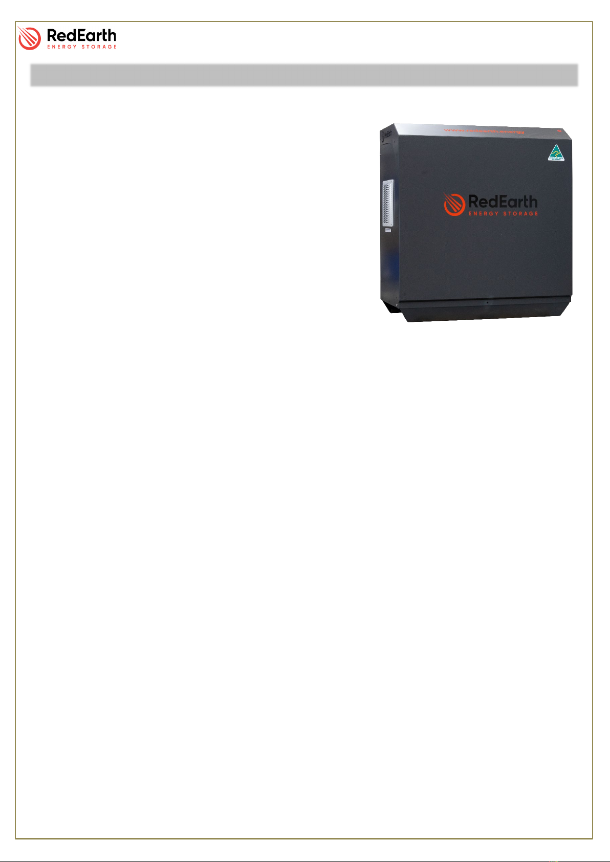
The SunRise Home Battery is an Australian-made battery system designed to reduce electricity
usage. The system generates and stores solar power for use day & night. The SunRise is fully
certified to AS4777.2, IEC62109-1/2 & AS60950.1 and conforms to the Battery Safety Guide.
The SunRise system can be installed with or without batteries. Batteries can easily be added later,
as demand grows and budgets allow. Batteries must be of the same make and model.
•When installed with batteries excess PV solar electricity generated during the day will be
used to reduce the amount of electricity imported from the grid at night. In addition the battery
ensures essential household loads (fridges, lights etc) can be powered during a power
outage. This uses an automatic transfer switch included inside the SunRise unit.
•When installed without batteries excess PV generated during the day can be exported to the
grid, which reduces your electicity bill. Ensuring you have the best electricity plan from your
provider will improve your return.
•The SunRise system can also easily be retrofitted to an existing PV solar system.
The SunRise combines an AS4777.2 certified SunGrow 5kW inveter (SH5K-30) with the following
battery options:
Up to 6 Troppo batteries (48VDC Lithium-ion 4.1kWh nominal each).
Up to 5x PylonTech (48VDC Lithium-ion 3.55kWh nominal each – Model US3000)
NOTE: This Installation Guide should be read in conjuction with the following Sungow, PylonTech
or RedEarth Troppo Manuals supplied with the system.
A total of 6.65kW of solar panels can be connected to the systems two MPPT’s to
claim full STCs (1.33 x 5.0kW). The maximum DC string voltage is 600VDC.
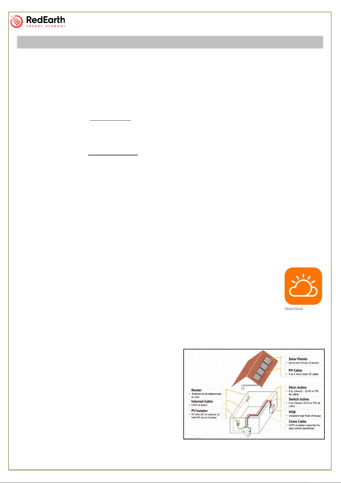
The SunRise SGS system can be remotely monitored via RedEarths’ monitoring web
portal or via their their app (iSolarCloud app).
A typical installation of the SunRise will have the following steps:
•Seperation of the Main Switchboad (MSB) into essential and non-essential.
•Installation of the meter, double-pole and bypass switch in the MSB
•Connection of the essential loads
•Connection of the non-essential loads
•Connection of the PV arrays
•Optional – CAT5 internet cable (to provide more
reliable comms for remote monitoring) WiFi is
included in the system as default.
Note: The SunRise is not designed to act as the
customers main switch board (MSB) as it does not
include space for additional main & customer circuit
breakers or RCDs.
Overview:

SunRise – Installation Manual
RE_PROD_0005 Version 3 Page 5 of 28 Issue Date 16/11/2020
SunRise Weight: 87kg plus 42kg per Troppo battery
Or 32kg per US3000 battery
Dimensions:
1040 H x 969 W x 544 D [mm]
SunRise Minimum Clearance
According to AS/NXS 5139
Dimensions & Clearance
SunRise (Mini) Weight: 61kg plus 42kg per
Troppo battery
Or 32kg per US3000 battery
Dimensions: 1040 H x 669 W x 543 D [mm]

SunRise – Installation Manual
RE_PROD_0005 Version 3 Page 6 of 28 Issue Date 16/11/2020
Opening the SunRise
RedEarth’s SunRise Home Battery System can be internally
accessed by removing the front cover. To do this, remove the nine
(9) screws with a Philips screwdriver (PH2), lift and pull the cover
away from the unit and place in a safe location.
Inside
The SunRise can be divided into three main areas. On the Lefthand side
(LHS) is the Inverter, in the middle are the batteries and on the Righthand
Side (RHS) are the electrical devices.
Righthand Side (RHS)
Here you will find the Sungrow SH5K-30 facing
outwards and all the connections to it are on the bottom side. Also in this area
are the terminal blocks that will communicate with the meter.
Middle
This general area is where the batteries are located. A complete set
will have either 5 Pylontech or 6 RedEarth Lithium Batteries
(SunRise Mini will have 3 RedEarth Lithium Batteries).
The terminals on the back panel and above the batteries are for
the connection of the thermal relay and the heat extraction fans.
Lefthand Side (LHS)
Here you will find all the connection points for the power cables and the
protection devices.
Access to this area is narrow and limited, we strongly recommend doing the
electrical connections before installing the batteries.
Components
Removal of the cover must only be
done by qualified personnel.

SunRise – Installation Manual
RE_PROD_0005 Version 3 Page 7 of 28 Issue Date 16/11/2020
The SunRise comes fully equipped with the following items.
•SunRise pre-wired enclosure
•Sungrow SH5K-30 inverter
•SunRise User Manual
•SunRise Installation Manual
•Battery Specifications
•Spare Parts Kit
oStickers & Traffolytes for a complete install
oMC4 connectors
oM25 glands (plain to screw)
oM25 plugs
o1x 32A Double pole circuit breaker
oSungrow meter (with CT)
oRemote monitoring device (optional)
Components

SunRise – Installation Manual
RE_PROD_0005 Version 3 Page 8 of 28 Issue Date 16/11/2020
8 steps for complete SunRise installation:
1. Transporting
2. Positioning
3. Solar Install
4. Electrical connections
4.1. Solar
4.2. Battery
4.3. Grid & EPS
4.4. Aux. Earth Fault Alarm
4.5. MSB & Meter
5. Turn on/Shutdown
6. Commissioning
7. Monitoring and Communications
8. Finalising and Handover
Step 1. Transporting
The SunRise system is wrapped in foam, heavy duty
cardboard and supplied on a pallet, is fully set-up and
ready to run. The system weighs around 87kg plus the
number of batteries (see Appendix B for individual
weight) and should be handled with caution and proper
lifting equipment.
Installation

SunRise – Installation Manual
RE_PROD_0005 Version 3 Page 9 of 28 Issue Date 16/11/2020
Step 2. Positioning
The SunRise is designed to be a freestanding weatherproof system. However,
we strongly recommend it to be placed outdoors and close (300mm) to a wall
in a shaded area to reduce the chances of overheating. It should also be placed
as close as possible to the solar panels and the MSB to minimise voltage
drop/power loss.
Cooling air flow passes up through the base of the system and then out the
back.
•Air vents are included in the base
and rear of the system. Do not block them otherwise the
system will overheat and shutdown. Once the system
cools down again it can be restarted. The flow of air is
assisted by an electric fan connected to one of the rear
vents. It is controlled by an adjustable temperature
switch set to 35⁰C in the factory.
•Allow spacing around the system to comply with current
installation standards.
The SunRise has four holes in the base to allow for securing.
This can be done with dynabolts or material appropriate screws.
NOTE: SunRise can be installed indoors. However, proper
ventilation must be installed according to AS/NZS 5139.
NOTE: Minimum distance between the wall and the back is 100mm
Step 3. Solar Install
The PV Array should be designed and installed in accordance with AS/NZS
5033 and the latest CEC Installation guidelines. Caution should be taken in
selecting PV panels and wiring method to ensure Open Circuit Voltage (VOC)
and Short Circuit Current (ISC) is not exceeded.
PV Racking & Panels should be installed in accordance with manufactures
instructions and AS/NZS 5033.
NOTE: Ensure that the array is within the inverter specification and polarity
of the array is correct.
Installation
SunRise Minimum Clearance
According to AS/NZS 5139
WARNING: The Solar DC Isolator on the SunRise must be in the off position
before any solar panels are connected

SunRise – Installation Manual
RE_PROD_0005 Version 3 Page 10 of 28 Issue Date 16/11/2020
Step 4. Electrical connections
NOTE: Before any electrical connections are made, check all internal connections are secure and
have not come loose during transport.
NOTE: Ensure that all breakers and isolators, as well as those supplying power to the unit, are
turned OFF.
SunRise is designed to be an extremely easy install. SunRise,
must be hardwired to a remote switchboard, which contains a
MEN and earth stake. To do so, open up the unit as explained in
“Opening the SunRise” and direct your attention to the RHS. Here
are the connection point needed for an install.
4.1. Solar
SunRise has 2 Maximum Power Point Trackers (MPPTs) and
allows for 1 array to be installed on each. For ease installation,
both MPPTs are on the same isolation device and come with the
identification tags (PV#1, PV#2) on each pair.
To connect the solar power, insert the unterminated cables into
the system and then terminate the correct MC4’s on the cables.
Once this is done, connect the PV cables to correct MC4 and
check for correct polarity and VOC.
4.2. Battery
Tested and commissioned in RedEarth factory, the batteries can be found in the middle section of
the SunRise.
If the batteries are to be removed during final transportation/positioning, see the procedure below
on how to remove/install the battery.
Installation

SunRise – Installation Manual
RE_PROD_0005 Version 3 Page 11 of 28 Issue Date 16/11/2020
•Removing/Installing Troppo Battery
To remove or install a battery, you will need to follow these steps:
•Remove the battery cables by pressing the button on
the side of the terminal and pull it straight up;
NOTE: When installing the battery cable, simply push it
onto the terminal until you hear a click.
•
Remove the bolt that holds the earth cable to the
battery;
•Remove the front rail that holds the batteries in place;
•Slide out one battery at a time. Be careful handling as
each battery weighs 42 kilograms.
To install a battery, follow this process in reverse.
Installation
ATTENTION: If the battery polarity is connected incorrectly it will damage other
batteries as well as the SunRise system.

SunRise – Installation Manual
RE_PROD_0005 Version 3 Page 12 of 28 Issue Date 16/11/2020
•Removing/Installing US3000 Battery
To remove or install a battery, you will need to follow these steps:
•Remove the battery cables by pressing the button on
the side of the terminal and pull it straight up;
NOTE: When installing the battery cable, simply push it
onto the terminal until you hear a click.
•
Remove the CAT5 communication cables;
•Remove the bolt that holds the earth cable to the
battery;
•Unclip the necessary fans so that the battery can be
removed without bumping into it;
NOTE: Do not remove the rail
as the batteries are
suspended. If removed, batteries will fall and be
damaged.
•Lift out one battery at a time. Be careful handling as
each battery weighs 32 kilograms.
To install a battery, follow this process in reverse.
Installation
ATTENTION: If the battery polarity is connected incorrectly it will damage other
batteries as well as the SunRise system.

SunRise – Installation Manual
RE_PROD_0005 Version 3 Page 13 of 28 Issue Date 16/11/2020
Grid and Emergency Power Supply (EPS)
To connect the cables to the system, secure the exposed end of the
cable into the correct terminal block and secure by tightening with a
flat-head screwdriver.
The Terminal Blocks are labelled as shown to the right.
4.3. Auxiliary Earth Fault Alarm
RedEarth’s Sunrise has two terminal blocks for the installation of a
third-party alarm. These 2 terminals are on the same din rail as the
EPS terminals and can be identified by their smaller size, with the grey
terminal set as the active and the blue the neutral.
To install the third-party alarm, replace the resistor (wrapped in heat-
shrink) with the new device.
Installation

SunRise – Installation Manual
RE_PROD_0005 Version 3 Page 14 of 28 Issue Date 16/11/2020
4.4. Main Switchboard (MSB) & Meter
In the MSB, three tasks must be done for a complete Sunrise Install:
•Separation of the circuits into non-essential and essential (EPS)
•Installation of the Sungrow meter
•Installation of the double pole breaker
If the property already has a PV system, when separating the circuits in the MSB keep the pre-
existing PV Inverter on the non-essential side.
As shown in the image below, when installing the Sungrow Meter, be sure to have it on the non-
essential side and have the CT clipped in between the Meter and the Main Circuit Breaker (with
the arrow pointing towards the loads.
The communication between the meter and the system can be done with a
CAT5 or CAT6 cable. Using 2 of the strands from the CAT cable, connect
one (A) to the terminal 24 and the other (B) to terminal 25, as shown. Inside
the SunRise and underneath the inverter are the terminals that the other end
of this CAT cable will connect to. Strip the end of strands A and B and
connect them to the correct terminals.
For easy comprehension, install the double pole breaker between the non-
essential and essential loads, as shown below.
.
Installation

SunRise – Installation Manual
RE_PROD_0005 Version 3 Page 15 of 28 Issue Date 16/11/2020
Step 5. Turning ON
NOTE: Turning the SunRise ON for the first time will require access to the batteries on the inside of
the unit. For all other times, the Turn ON procedure is the reverse of the shutdown procedure.
•If using Troppo batteries, to turn ON the unit for the first time, you must follow the steps
below:
1 Switch ON all individual battery breakers;
2 Switch ON the BATTERY SYSTEM D.C. ISOLATOR (#3);
3 Switch ON both SOLAR D.C. ISOLATORS (#2);
4 Turn the ByPass Switch to Normal Operation (upwards);
5 Turn ON all AC circuit breakers (#1);
1
2
3
4
5
Installation

SunRise – Installation Manual
RE_PROD_0005 Version 3 Page 16 of 28 Issue Date 16/11/2020
•If using US3000 batteries, to turn ON the unit for the first time, you must follow the steps
below:
1 Switch ON the all battery “POWER” switches;
2 Press the SW (red) button on the Master Battery;
3 Switch ON the BATTERY SYSTEM D.C. ISOLATOR (#3);
4 Switch ON both SOLAR D.C. ISOLATORS (#2);
5 Turn the ByPass Switch to Normal Operation (upwards);
6 Turn ON all AC circuit breakers (#1);
1
2
3
4
5
6
Installation

SunRise – Installation Manual
RE_PROD_0005 Version 3 Page 17 of 28 Issue Date 16/11/2020
Shutting Down
The shutdown procedure is the reverse of the “turn on” procedure and is shown below. This
procedure can be found on the RHS of the unit.
1 Turn OFF all AC circuit breakers (#1);
2 Switch OFF the SOLAR D.C. ISOLATORS (#2);
3 Switch OFF the BATTERY SYSTEM D.C. ISOLATOR (#3);
NOTE: The breaker on the BMU also disconnects the batteries from the inverter. In normal
operation, this should not have to be used.
NOTE: After a few minutes with the system turned off, the battery will have to be “awaken” manually
via the app iSolarCloud.
Installation

SunRise – Installation Manual
RE_PROD_0005 Version 3 Page 18 of 28 Issue Date 16/11/2020
Step 6. Commissioning
The SunRise is commissioned and tested in RedEarth’s factory to guarantee correct operation of
the system as ordered. However, last-minute parameter adjustments may be required (eg. Export
limitation). Carefully follow the procedure in Chapter 8 of the Sungrow User Manual on how to make
these alterations without compromising the existing configuration.
NOTE: This must be done by a qualified person.
After successful installation, the LDC screen will display as below. If dashes appear instead of
numbers, the installation is incorrect and must be fixed.
Fan Control Adjustment:
The thermostat is located inside the unit next to the GPO’s. This
automatically starts the fans once the temperature rises above the
set-point. This set-point can easily be adjusted with a small
screwdriver. It is set to 35⁰ Celsius in the factory.
Installation

SunRise – Installation Manual
RE_PROD_0005 Version 3 Page 19 of 28 Issue Date 16/11/2020
Step 7. Monitoring and Communication
There are currently two ways to enable monitoring to the SunRise.
•4G Antenna
•Hardwire to LAN
The first option uses RedEarth’s monitoring hardware and
requires positioning the antenna in a good 4G reception area.
To do this, pass the antenna through the antenna access
point and secure it with the appropriate size gland (available
in parts kit box).
If installing in a closed area i.e. Shed, remember to check the
4G signal with the doors closed as this will affect the strength
of the signal.
Once this is done as well as the start-up procedure, call
RedEarth – Tech Support to confirm its operation.
The second option requires a CAT5 or CAT6 cable with one
end plugged into the customer’s router and the other into the RJ45 port on the monitoring hardware.
As long as the 4G reception is adequate (or properly hardwired to the router) this does not require
commissioning as it is done and tested in factory
NOTE: Installer login is available in addition to customer logins. Contact Tech support for
information.
Step 8. Finalising and Handover
Before handing over the system, go through the following items and be sure that they have been
completed.
•The PV cables have the correct polarity and are correctly connected to the MC4s provided.
•Grid and EPS cable are tightly connected to the terminals block and have correct phase
rotation.
•Proper weatherproof seal on the entrance/exit gland from the SunRise
•The battery terminal connections are tight. (check after transportation)
•Check that the system operation is correct in all situations.
•Check screws holding the lid down are in place and tight. Pull on the vents and fans to check
that they are properly attached and will not come loose.
•Explain to the customer how the system operates.
Installation

SunRise – Installation Manual
RE_PROD_0005 Version 3 Page 20 of 28 Issue Date 16/11/2020
NORMAL OPERATION:
In this operation mode the Sunrise will operate as
explained above. Where the system uses solar, battery
and grid depending on the situation.
All of the breakers and isolators should be on the ON
position and the ByPass Switch should be in the upwards
position ( I ).
BYPASS OPERATION
In the ByPass operation mode, the system will
completely bypass the inverter and the grid will provide
power directly to the EPS loads.
For this to happen, all breakers and isolators should be
turned OFF and the ByPass Switch should be in the
downwards position ( II )
NOTE: The breaker in the switchboard (labelled “BATTERY SYSTEM CIRCUIT BREAKER”) must
always be tuned on.
NOTE: With the BYAPASS SWITCH In the middle position, all EPS circuit will loose power.
How to Operate a SunRise
Other manuals for SunRise Single Phase
1
Table of contents
Other RedEarth Inverter manuals
Popular Inverter manuals by other brands

Northern Lights
Northern Lights O843K Operator's manual

Generac Power Systems
Generac Power Systems 4270-0 Owner's manual and installation instructions

Hitachi
Hitachi WL200 Series Basic Manual

Link electronics
Link electronics IEC-833 Specification sheet

Steca
Steca coolcept StecaGrid 1800 Installation and operating instructions

LiteGear
LiteGear Inverter Power System Installation instructions and user manual